ESP SSANGYONG KORANDO 2013 Service Manual
[x] Cancel search | Manufacturer: SSANGYONG, Model Year: 2013, Model line: KORANDO, Model: SSANGYONG KORANDO 2013Pages: 1336, PDF Size: 92.18 MB
Page 1142 of 1336
0000-00
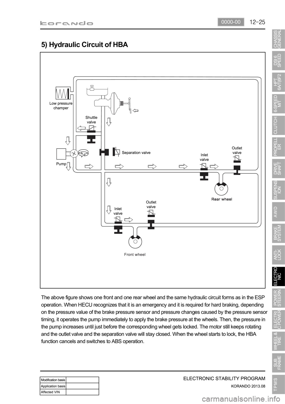
5) Hydraulic Circuit of HBA
The above figure shows one front and one rear wheel and the same hydraulic circuit forms as in the ESP
operation. When HECU recognizes that it is an emergency and it is required for hard braking, depending
on the pressure value of the brake pressure sensor and pressure changes caused by the pressure sensor
timing, it operates the pump immediately to apply the brake pressure at the wheels. Then, the pressure in
the pump increases until just before the corresponding wheel gets locked. The motor still keeps rotating
and the outlet valve and the separation valve will stay closed. When the wheel starts to lock, the HBA
function cancels and switches to ABS operation.
Page 1143 of 1336
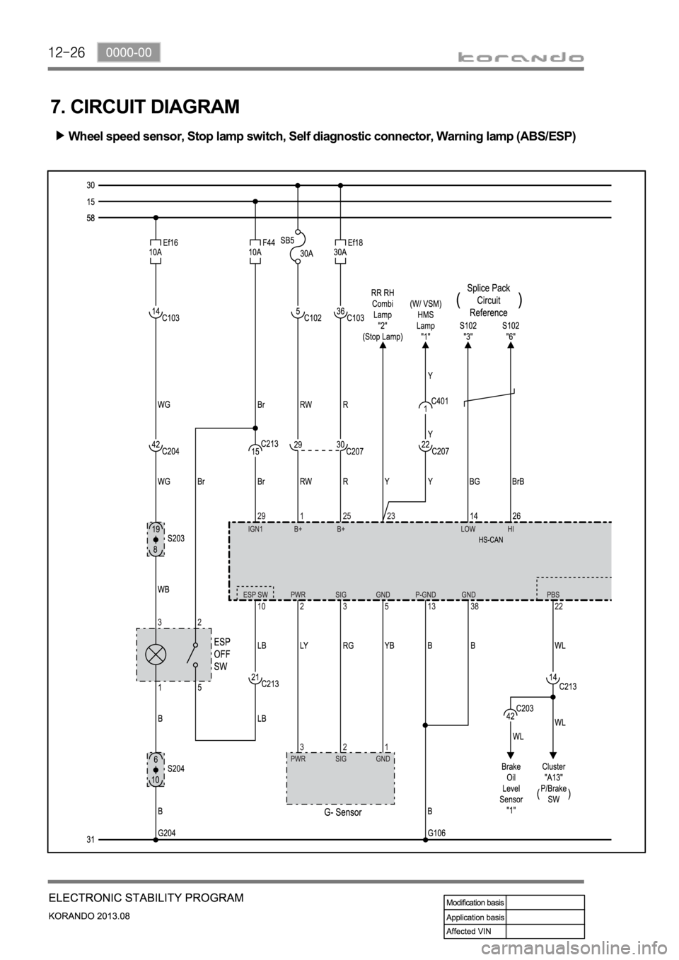
7. CIRCUIT DIAGRAM
Wheel speed sensor, Stop lamp switch, Self diagnostic connector, Warning lamp (ABS/ESP)
Page 1162 of 1336
If weight is not equally distributed around the wheel, unbalance centrifugal force by the wheel rotation
produces vibration. As the centrifugal force is produced proportional to the square of the rotating speed,
the wheel weight should be balanced even at high speed. There are two types of the tire and wheel
balancing: static and dynamic. Abnormal vibration may also occur due to unbalanced rigidity or size of
tires.
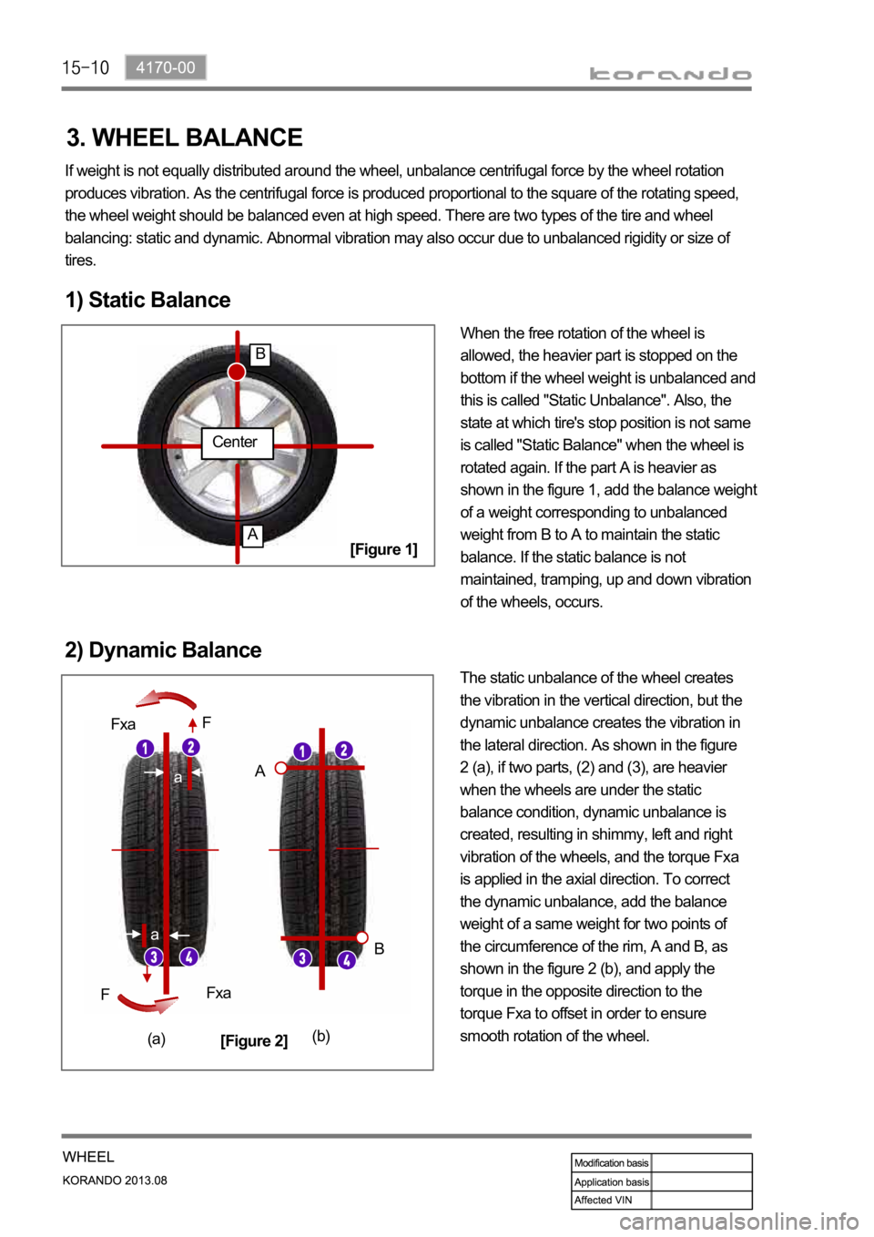
1) Static Balance
When the free rotation of the wheel is
allowed, the heavier part is stopped on the
bottom if the wheel weight is unbalanced and
this is called "Static Unbalance". Also, the
state at which tire's stop position is not same
is called "Static Balance" when the wheel is
rotated again. If the part A is heavier as
shown in the figure 1, add the balance weight
of a weight corresponding to unbalanced
weight from B to A to maintain the static
balance. If the static balance is not
maintained, tramping, up and down vibration
of the wheels, occurs.
2) Dynamic Balance
The static unbalance of the wheel creates
the vibration in the vertical direction, but the
dynamic unbalance creates the vibration in
the lateral direction. As shown in the figure
2 (a), if two parts, (2) and (3), are heavier
when the wheels are under the static
balance condition, dynamic unbalance is
created, resulting in shimmy, left and right
vibration of the wheels, and the torque Fxa
is applied in the axial direction. To correct
the dynamic unbalance, add the balance
weight of a same weight for two points of
the circumference of the rim, A and B, as
shown in the figure 2 (b), and apply the
torque in the opposite direction to the
torque Fxa to offset in order to ensure
smooth rotation of the wheel.
Center
A
B
a
a
Fxa
Fxa F
F
A
B
(a)(b)
[Figure 1]
[Figure 2]
3. WHEEL BALANCE
Page 1183 of 1336

1) DOT LCD Display Related to TPMS
Status DOT LCD display Condition & illumination method
Correct tire pressureThe specified tire pressure is based on a
cold tire with the vehicle unloaded (no
Excessive tire pressureCorresponding status lamp blinks with
reverse shading at interval of 0.4 seconds if
tire pressure is 50 psi or higher
Low tire pressureWhen tire pressure is less than 13~20% of
specified value for a period of time,
corresponding status lamp blinks with
reverse shading for 70 seconds at interval o
f
0.4 seconds
Lower than minimum tire
pressureCorresponding status lamp comes on if tire
pressure is 24 psi or less
Sudden tire pressure lossCorresponding status lamp blinks with
shading reverse at interval of 0.4 seconds if
tire pressure changes more than 3 psi per 1
minute at speed of 0 km/h or above.
Imbalance between left and
right tire pressureCorresponding status lamps blink
alternately at interval of 1.0 second if tire
pressure differs by more than 4 psi in the left
and right tires while driving for more than 10
minutes
Impossible to determine tire
pressurePressure of the tire displayed as "--" when
not possible to determine tire pressure
correctly
* At initial start, the tire pressure can be
displayed after 10 minutes of driving at
speed of 20 km/h or higher
Supervision type
Page 1196 of 1336
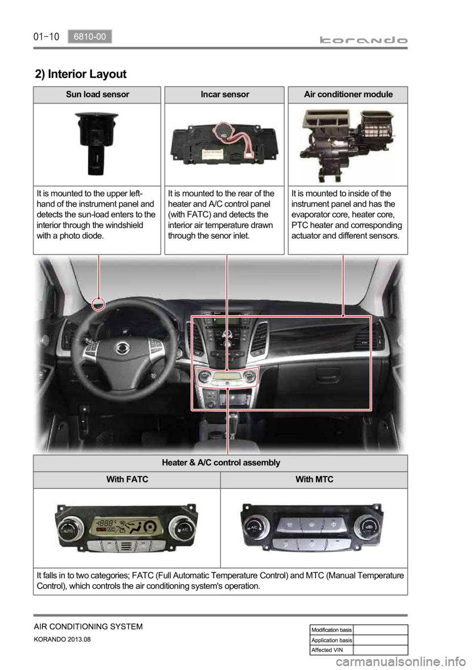
2) Interior Layout
Sun load sensor
It is mounted to the upper left-
hand of the instrument panel and
detects the sun-load enters to the
interior through the windshield
with a photo diode. Incar sensor
It is mounted to the rear of the
heater and A/C control panel
(with FATC) and detects the
interior air temperature drawn
through the senor inlet.Air conditioner module
It is mounted to inside of the
instrument panel and has the
evaporator core, heater core,
PTC heater and corresponding
actuator and different sensors.
Heater & A/C control assembly
With FATC With MTC
It falls in to two categories; FATC (Full Automatic Temperature Control) and MTC (Manual Temperature
Control), which controls the air conditioning system's operation.
Page 1229 of 1336
3. CAUTIONS FOR AIR BAG SYSTEM
Cautions for air bag maintenance
Whenever installing or removing the devices related to the air bag system, disconnect the negative
battery cable and wait for at least 30 seconds.
Do not connect a tester probe to the inflator to measure the resistance of the component of the air
bag system. The detonator of the inflator may explode due to a sudden extra power supplied by the
tester.
Note that the used components related to the air bag system, especially the air bag unit, should be
packed in an air tight container and prevent it from any impact or damage.
When there is any deployed air bag (including curtain air bag and seat belt pretensioner), the entire
system including the air bag unit should be replaced. The deployed air bag unit should not be reused
since it has status data when it is deployed, and the data cannot be cleared with a diagnostic device.
The air bag and seat belt pretensioner systems contain explosive charges, so handle carefully when
disposing or replacing them. 1.
2.
3.
4.
5.
Cautions for air bag maintenance
Do not modify, change or apply impact on any air bag component. The air bag may be deployed
abruptly, causing serious injuries.
Children and infants should ride in a rear seat. Seating in the passenger seat with carrying a
child or infant is strictly prohibited. An infant or a child could be severely injured by the air bag
deployment.
A child restraint system must not be installed on the front seat. An infant or a child could be severely
injured by the air bag deployment when it is fitted to the passenger seat.
Do not place any objects on the air bag inflation location. You may get injured by those objects during
deployment.
Never put your arms around the front seat from behind, lean on the front seatback, or put your arms
out of the window. You can severely injured when the side air bag deploys.
Never lean on the door since it becomes very dangerous when the side air bag deploys.
The side air bag deploys when there is a severe side collision.
Do not slam the front door to close it. The side air bag may deploy unexpectedly.
When an occupant fastens the seat belt in an unstable or inclined posture, the air bag system cannot
protect the occupant properly. Moreover, the occupant can be injured by the air bag.
Do not move your seat too close to the steering wheel or dashboard. Being too close to the
steering wheel or instrument panel during the air bag deployment could cause serious injury,
including death
Hold only the outer rim of the steering so that the air bag can inflate without any hindrance.
Do not incline toward the steering wheel. Never allow the passenger to put hands or feet on the dash
board. The air bag cannot work properly Do not hold and operate the steering wheel by crossing your
arms You could get seriously injured when the air bag deploys. 1.
2.
3.
4.
5.
6.
7.
8.
9.
10.
11.
Page 1235 of 1336

3. AIR BAG SYSTEM OPERATING PROCESS
1) Air Bag System Input/Output
The air bag unit (SDM) performs the internal/external diagnosis on the air bag system for about 6
seconds after IGN ON. The air bag unit is ready to deploy air bag after this diagnosis, and when a
certain level of collision occurs, it determines the deployment of the air bag using the signals from the
impact sensors, deploys the corresponding air bag, and stores the collision data and EDR data. The
body control module (BCM) activates the auto door unlock function and various lamps including hazard
warning lamp and room lamps, when the crash signal from the SDM is received to notify others of
emergency situation and let the occupant escape easily.
Major functions
Detects frontal and side collision (Rear-end collision only with EDR trigger)
Activates the front air bag, side air bag, curtain air bag and belt pretensioners
Indicates system readiness and faults to the driver by means of a fault warning lamp
Facilitates servicing capability via a serial diagnostic communication interfaces
Records crash data and DTCs
Keeps power for deployment of air bag even when the power to the air bag unit is cut off due to the
collision
Event data recorder (EDR) -
-
-
-
-
-
-
Page 1240 of 1336
8810-00
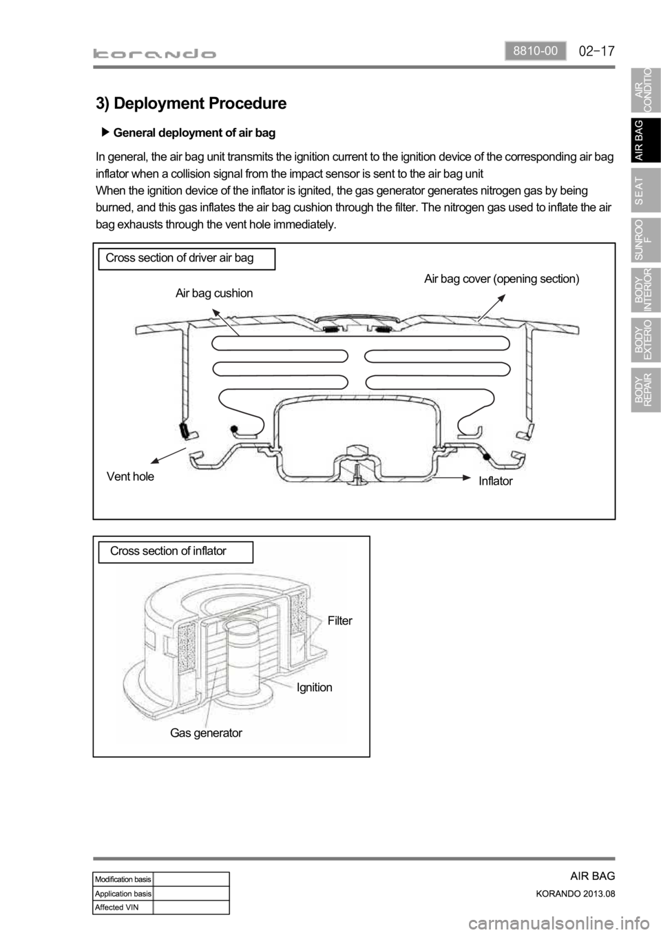
General deployment of air bag
3) Deployment Procedure
Air bag cover (opening section)
Air bag cushion
Vent hole
Inflator
Filter
Ignition
Gas generator In general, the air bag unit transmits the ignition current to the ignition device of the corresponding air bag
inflator when a collision signal from the impact sensor is sent to the air bag unit
When the ignition device of the inflator is ignited, the gas generator generates nitrogen gas by being
burned, and this gas inflates the air bag cushion through the filter. The nitrogen gas used to inflate the air
bag exhausts through the vent hole immediately.
Cross section of driver air bag
Cross section of inflator
Page 1276 of 1336

7410-00
5) Front Seat Heated Wire and Ventilation Operation
Operating conditions
Engine running
If the engine starts to crank during the seat heated wire and ventilation signal output, the seat heated
wire will not be operated until the cranking stops. -
-
Operation description
After the ignition is turned on, the temperature of the seat can be adjusted in 3 levels (Level 2
pressed, the temperature level goes down by one level. Pressing the switch a third time will turn off
the operation. -
Operating process
When the front seat heated wire and ventilation switch is pressed, the front seat heated wire and
ventilation unit supplies the power to the corresponding seat for heated wire and ventilation operation
through the switch. -
The heated wire and ventilation functions cannot be operated at the same time.
(1) Heated wire and ventilation functions for front seat (driver seat heated
wire and ventilation - 2 levels, passenger seat heated wire - 2 levels)
Page 1277 of 1336
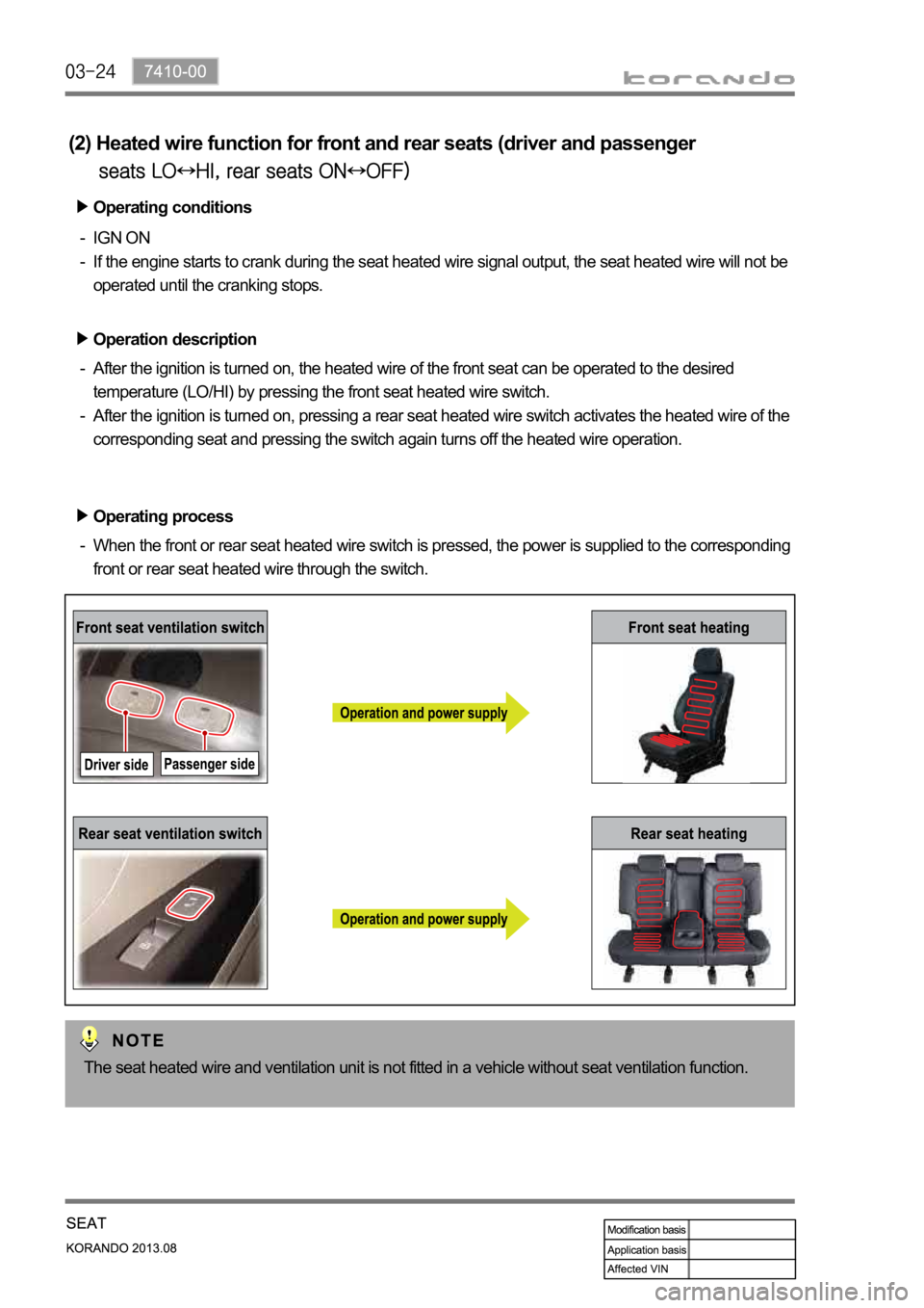
Operating conditions
IGN ON
If the engine starts to crank during the seat heated wire signal output, the seat heated wire will not be
operated until the cranking stops. -
-
Operation description
After the ignition is turned on, the heated wire of the front seat can be operated to the desired
temperature (LO/HI) by pressing the front seat heated wire switch.
After the ignition is turned on, pressing a rear seat heated wire switch activates the heated wire of the
corresponding seat and pressing the switch again turns off the heated wire operation. -
-
Operating process
When the front or rear seat heated wire switch is pressed, the power is supplied to the corresponding
front or rear seat heated wire through the switch. -
The seat heated wire and ventilation unit is not fitted in a vehicle without seat ventilation function.
(2) Heated wire function for front and rear seats (driver and passenger