ESP SSANGYONG KORANDO 2013 Manual PDF
[x] Cancel search | Manufacturer: SSANGYONG, Model Year: 2013, Model line: KORANDO, Model: SSANGYONG KORANDO 2013Pages: 1336, PDF Size: 92.18 MB
Page 985 of 1336
0000-00
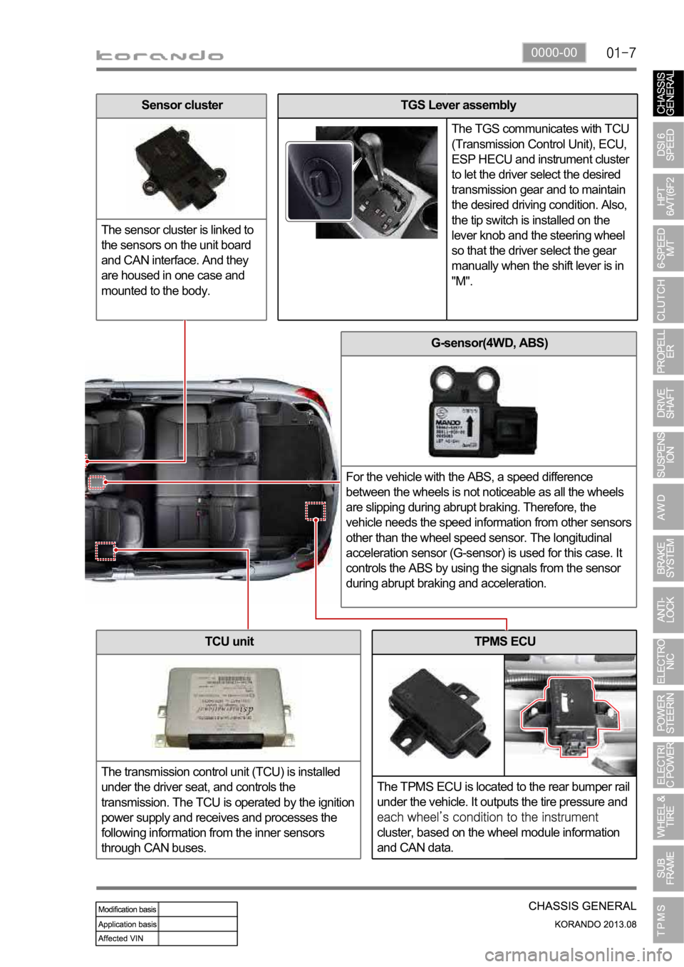
TPMS ECU
The TPMS ECU is located to the rear bumper rail
under the vehicle. It outputs the tire pressure and
cluster, based on the wheel module information
and CAN data.
G-sensor(4WD, ABS)
For the vehicle with the ABS, a speed difference
between the wheels is not noticeable as all the wheels
are slipping during abrupt braking. Therefore, the
vehicle needs the speed information from other sensors
other than the wheel speed sensor. The longitudinal
acceleration sensor (G-sensor) is used for this case. It
controls the ABS by using the signals from the sensor
during abrupt braking and acceleration.
TCU unit
The transmission control unit (TCU) is installed
under the driver seat, and controls the
transmission. The TCU is operated by the ignition
power supply and receives and processes the
following information from the inner sensors
through CAN buses.
TGS Lever assembly
The TGS communicates with TCU
(Transmission Control Unit), ECU,
ESP HECU and instrument cluster
to let the driver select the desired
transmission gear and to maintain
the desired driving condition. Also,
the tip switch is installed on the
lever knob and the steering wheel
so that the driver select the gear
manually when the shift lever is in
"M".Sensor cluster
The sensor cluster is linked to
the sensors on the unit board
and CAN interface. And they
are housed in one case and
mounted to the body.
Page 986 of 1336
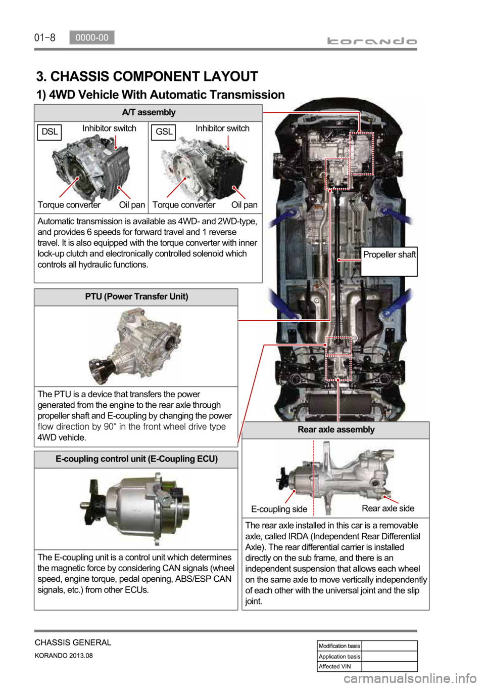
A/T assembly
Automatic transmission is available as 4WD- and 2WD-type,
and provides 6 speeds for forward travel and 1 reverse
travel. It is also equipped with the torque converter with inner
lock-up clutch and electronically controlled solenoid which
controls all hydraulic functions.
3. CHASSIS COMPONENT LAYOUT
PTU (Power Transfer Unit)
The PTU is a device that transfers the power
generated from the engine to the rear axle through
propeller shaft and E-coupling by changing the power
4WD vehicle.Rear axle assembly
The rear axle installed in this car is a removable
axle, called IRDA (Independent Rear Differential
Axle). The rear differential carrier is installed
directly on the sub frame, and there is an
independent suspension that allows each wheel
on the same axle to move vertically independentl
y
of each other with the universal joint and the slip
joint.
E-coupling control unit (E-Coupling ECU)
The E-coupling unit is a control unit which determines
the magnetic force by considering CAN signals (wheel
speed, engine torque, pedal opening, ABS/ESP CAN
signals, etc.) from other ECUs.
Inhibitor switch
Torque converter Oil pan
E-coupling sideRear axle side
Propeller shaft
1) 4WD Vehicle With Automatic Transmission
GSLDSLInhibitor switch
Torque converter Oil pan
Page 994 of 1336

A. Indicators on instrument cluster
C. HECU assembly
The HECU assemblies for ABS and ESP have
similar appearance but they have different inner
structure and connector connections from each
other. D. Front brake assembly
The disc brake for 4WD vehicle is the same with
the one for 2WD vehicle.
7. BRAKE SYSTEM AND ESP SYSTEM LAYOUT
B. Master cylinder assembly
Description for master cylinder in this chapter is
based on ABS/ESP equipped vehicle. For CBS,
there is an extra pressure valve mounted to the
master cylinder.
CaliperDisc
Parking brake
warning light
ABS warning lamp
ESP indicator
Page 999 of 1336
0000-00
3) General Instructions
Before lifting up the vehicle with a lift, correctly support the lifting points.
When using a jack, park the vehicle on a level ground and place the wheel chocks under the tires.
Position the jack under the frame and lift up the vehicle and then support with chassis stand before
service work.
Make sure to disconnect the negative (-) cable from the battery to prevent any damage to electric
systems.
If you have to work on vehicle, cover the seats and floor with protection covers to avoid any
damage and contamination.
Brake fluid and anti-freeze can damage the painted surface of body. So carefully handle them
during service work.
To improve the efficiency of service work, use only recommended and specified tools.
Use only Ssangyong genuine spare parts.
Never reuse the cotter pin, gasket, O-ring, oil seal, lock washer and self-locking nut. Replace them
with new ones. If reused, normal functions cannot be maintained.
Store the disassembled parts as a set based on disassembly order and unit.
Pay particular attention not to miss or mix the fasteners.
If necessary, especially for inspection, clean the removed parts completely.
Apply the oil or grease on the running and sliding surfeces before installation. Use the specified
sealant and gasket to prevent leakage if necessary.
Tighten the fasteners to the specified tightening torque.
As a final stage of service work, check if the serviced system is working properly and the problem
has been eliminated clearly. (1)
(2)
(3)
(4)
(5)
(6)
(7)
(8)
(9)
(10)
(11)
(12)
(13)
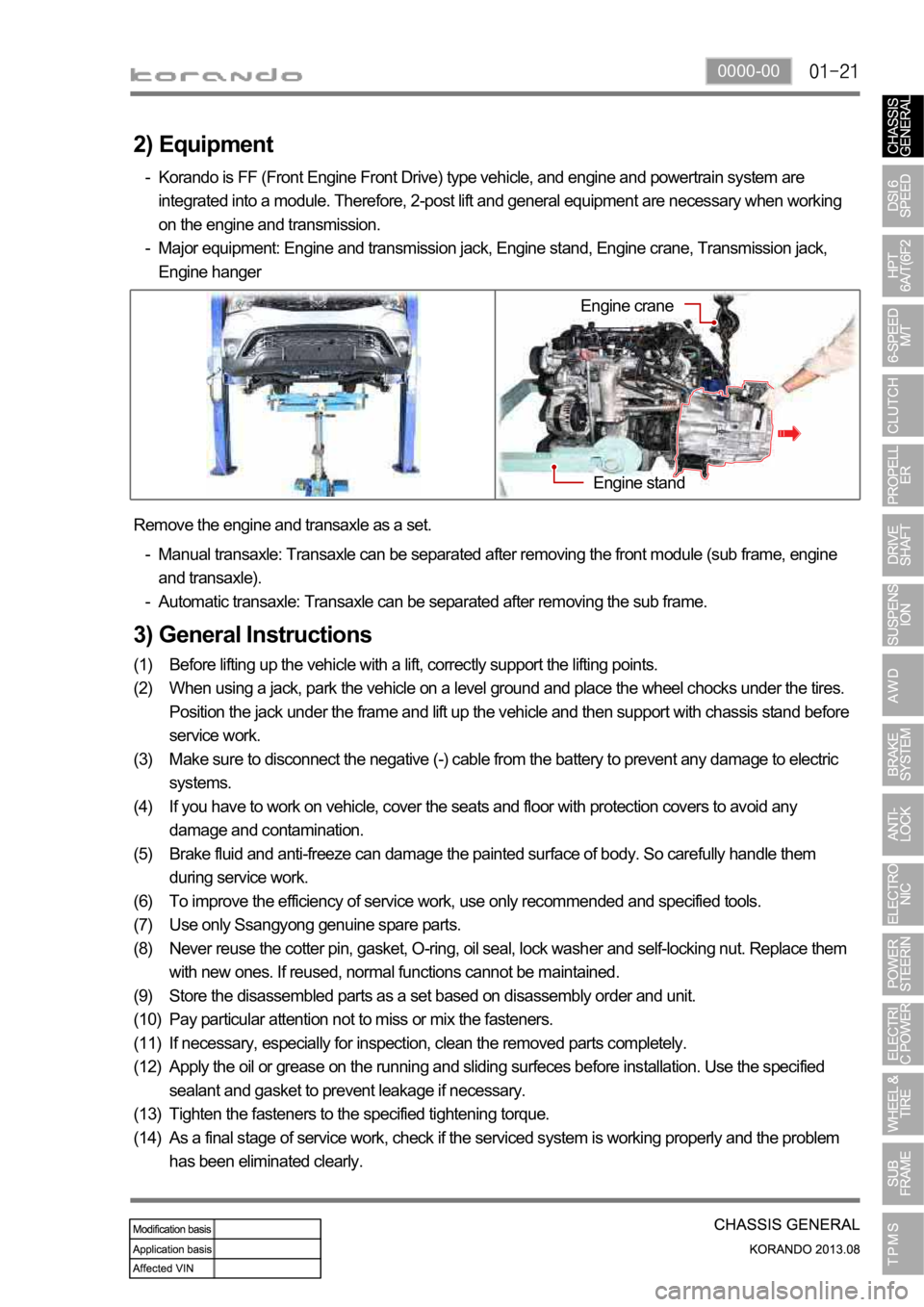
(14) Remove the engine and transaxle as a set.
Manual transaxle: Transaxle can be separated after removing the front module (sub frame, engine
and transaxle).
Automatic transaxle: Transaxle can be separated after removing the sub frame. -
-
2) Equipment
Korando is FF (Front Engine Front Drive) type vehicle, and engine and powertrain system are
integrated into a module. Therefore, 2-post lift and general equipment are necessary when working
on the engine and transmission.
Major equipment: Engine and transmission jack, Engine stand, Engine crane, Transmission jack,
Engine hanger -
-
Engine stand
Engine crane
Page 1076 of 1336
4110-01
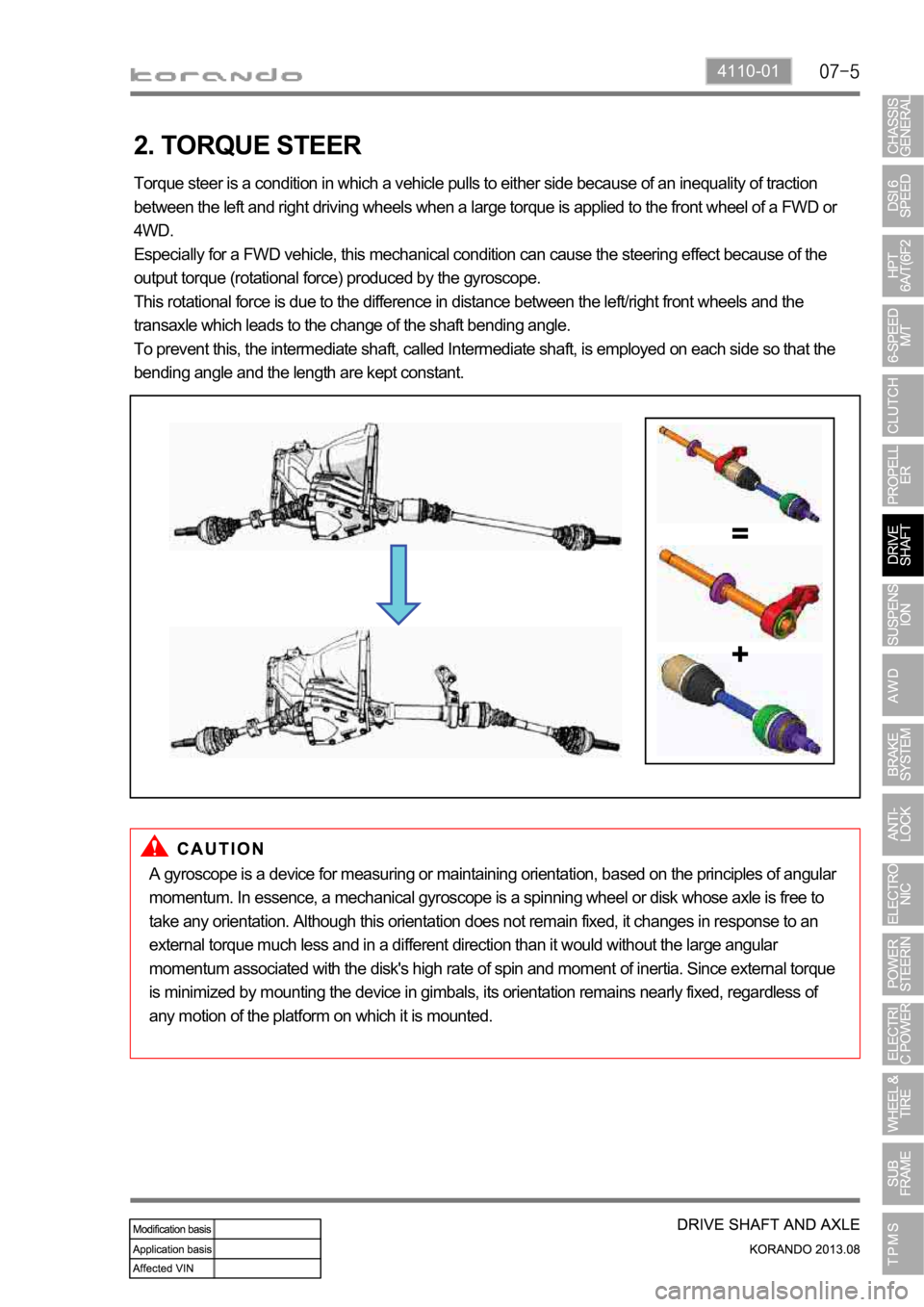
2. TORQUE STEER
Torque steer is a condition in which a vehicle pulls to either side because of an inequality of traction
between the left and right driving wheels when a large torque is applied to the front wheel of a FWD or
4WD.
Especially for a FWD vehicle, this mechanical condition can cause the steering effect because of the
output torque (rotational force) produced by the gyroscope.
This rotational force is due to the difference in distance between the left/right front wheels and the
transaxle which leads to the change of the shaft bending angle.
To prevent this, the intermediate shaft, called Intermediate shaft, is employed on each side so that the
bending angle and the length are kept constant.
A gyroscope is a device for measuring or maintaining orientation, based on the principles of angular
momentum. In essence, a mechanical gyroscope is a spinning wheel or disk whose axle is free to
take any orientation. Although this orientation does not remain fixed, it changes in response to an
external torque much less and in a different direction than it would without the large angular
momentum associated with the disk's high rate of spin and moment of inertia. Since external torque
is minimized by mounting the device in gimbals, its orientation remains nearly fixed, regardless of
any motion of the platform on which it is mounted.
Page 1083 of 1336
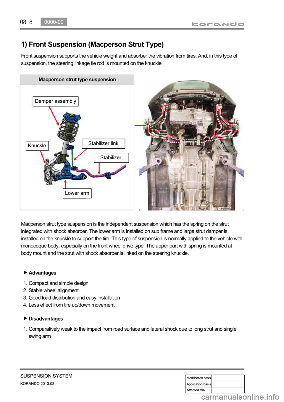
1) Front Suspension (Macperson Strut Type)
Front suspension supports the vehicle weight and absorber the vibration from tires. And, in this type of
suspension, the steering linkage tie rod is mounted on the knuckle.
Macperson strut type suspension is the independent suspension which has the spring on the strut
integrated with shock absorber. The lower arm is installed on sub frame and large strut damper is
installed on the knuckle to support the tire. This type of suspension is normally applied to the vehicle with
monocoque body, especially on the front wheel drive type. The upper part with spring is mounted at
body mount and the strut with shock absorber is linked on the steering knuckle.
Advantages
Compact and simple design
Stable wheel alignment
Good load distribution and easy installation
Less effect from tire up/down movement 1.
2.
3.
4.
Disadvantages
Comparatively weak to the impact from road surface and lateral shock due to long strut and single
swing arm 1.
Macperson strut type suspension
Page 1087 of 1336
0000-00
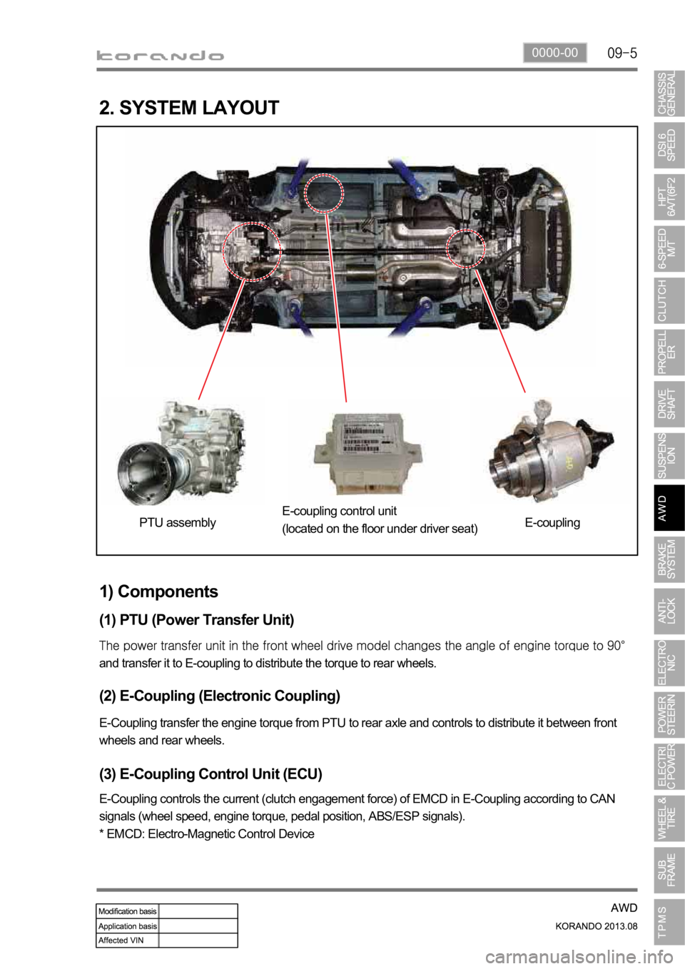
2. SYSTEM LAYOUT
1) Components
(1) PTU (Power Transfer Unit)
and transfer it to E-coupling to distribute the torque to rear wheels.
(2) E-Coupling (Electronic Coupling)
E-Coupling transfer the engine torque from PTU to rear axle and controls to distribute it between front
wheels and rear wheels.
(3) E-Coupling Control Unit (ECU)
E-Coupling controls the current (clutch engagement force) of EMCD in E-Coupling according to CAN
signals (wheel speed, engine torque, pedal position, ABS/ESP signals).
* EMCD: Electro-Magnetic Control Device PTU assemblyE-coupling control unit
(located on the floor under driver seat)E-coupling
Page 1088 of 1336

4850-00
1. SYSTEM OVERVIEW
1) Terms and Definition
CBS: Conventional Brake System
ABS: Anti-Lock Brake System
EBD: Electronic brake-Force Distribution
ESP: Electronic Stability Program
ABD: Automatic Braking Differential
ASR: Acceleration Slip Regulation
AYC: Active Yaw Control (Understeer and Oversteer Control)
HBA: Hydraulic Brake Assistant
ARP: Active Rollover Protection
HSA: Hill Start Assistant -
-
-
-
-
-
-
-
-
-
2) Functions
FunctionVehicle with CBS
Vehicle with ABS/EBD Vehicle with ESP
ABS
Not appliedApplied
Applied EBD Applied
ABD
Not applied ASR
AYC
HBA
ARP
HSA
Page 1089 of 1336
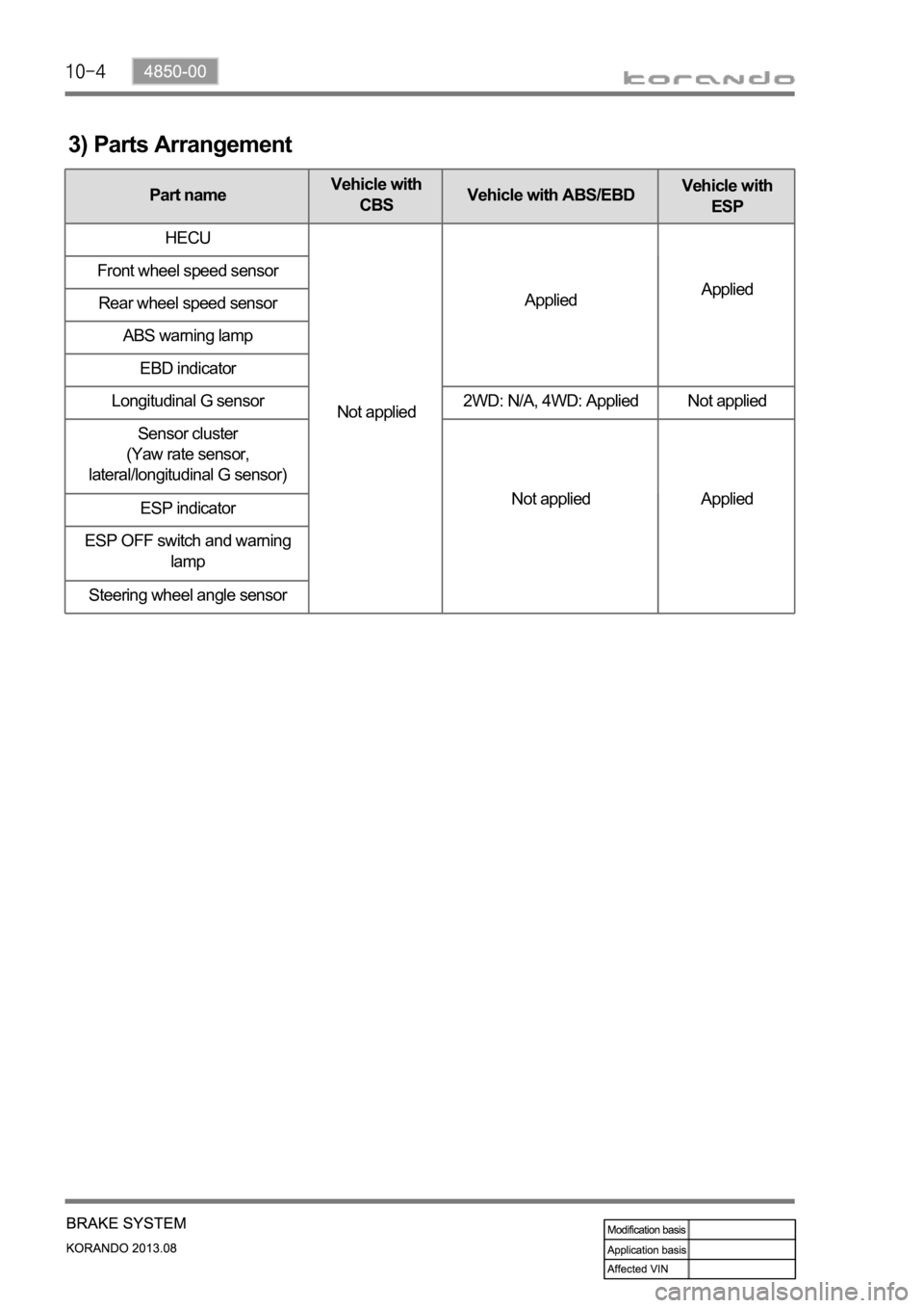
3) Parts Arrangement
Part nameVehicle with
CBSVehicle with ABS/EBDVehicle with
ESP
HECU
Not appliedAppliedApplied Front wheel speed sensor
Rear wheel speed sensor
ABS warning lamp
EBD indicator
Longitudinal G sensor 2WD: N/A, 4WD: Applied Not applied
Sensor cluster
(Yaw rate sensor,
lateral/longitudinal G sensor)
Not applied Applied
ESP indicator
ESP OFF switch and warning
lamp
Steering wheel angle sensor
Page 1090 of 1336

4850-00
A. Meter cluster-ABS, EBD, ESP
indicator/warning lampB. Master cylinder and
boosterC. HECU
F. Front/rear wheel speed sensor
Front/rear-4WD Rear-2WDH. Parking brakeG. Brake pedal
4) Component
ABS warning lamp
ESP indicator
D. Front brake
assembly
E. Rear brake
assembly
Disc
Disc
Parking brake
warning lamp
Caliper
Caliper