SSANGYONG KORANDO 2013 Service Manual
KORANDO 2013
SSANGYONG
SSANGYONG
https://www.carmanualsonline.info/img/67/57503/w960_57503-0.png
SSANGYONG KORANDO 2013 Service Manual
Trending: warning light, change key battery, relay, gear box, park assist, glass key, brake fluid
Page 1161 of 1336
4170-00
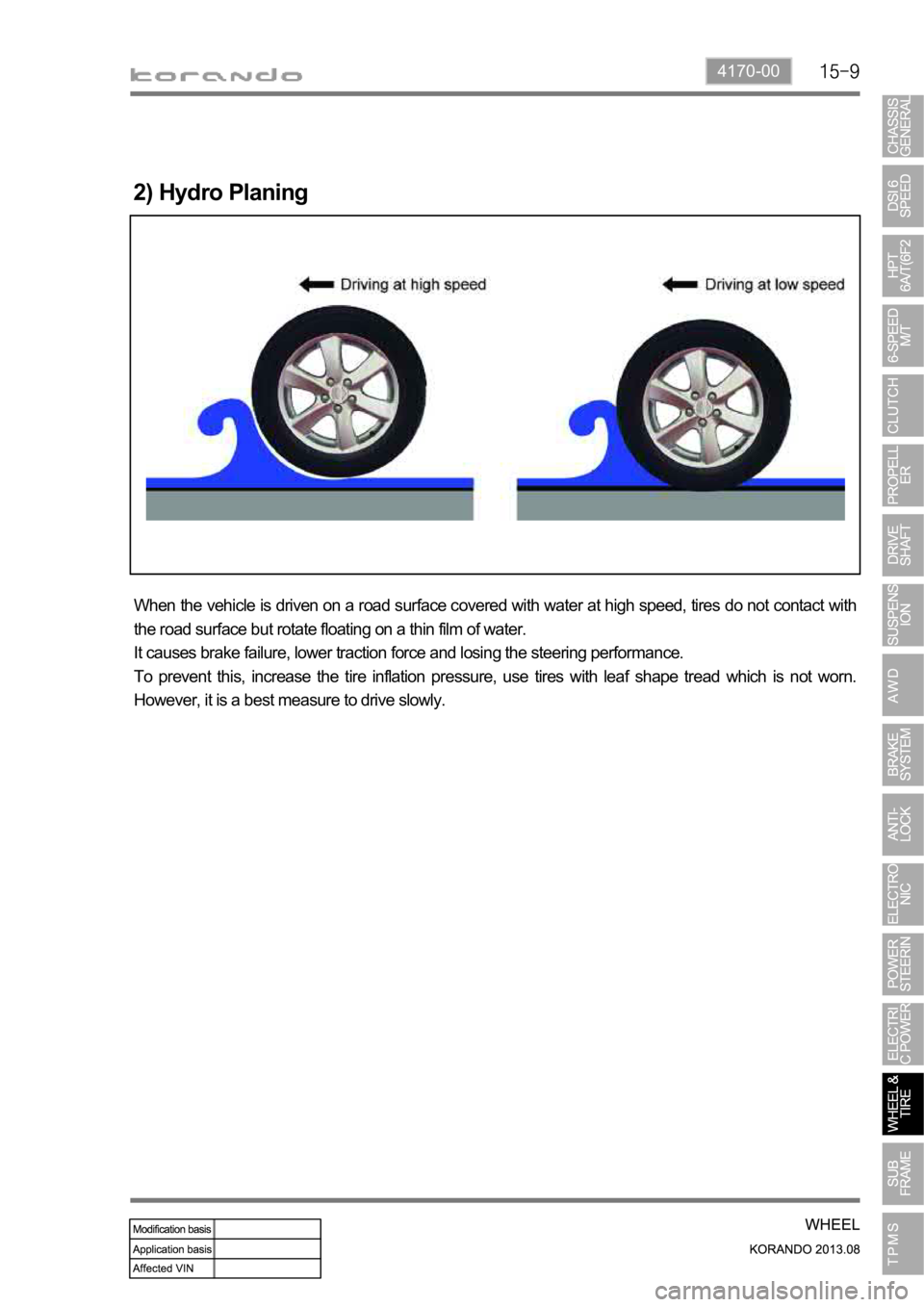
When the vehicle is driven on a road surface covered with water at high speed, tires do not contact with
the road surface but rotate floating on a thin film of water.
It causes brake failure, lower traction force and losing the steering performance.
To prevent this, increase the tire inflation pressure, use tires with leaf shape tread which is not worn.
However, it is a best measure to drive slowly.
2) Hydro Planing
Page 1162 of 1336
If weight is not equally distributed around the wheel, unbalance centrifugal force by the wheel rotation
produces vibration. As the centrifugal force is produced proportional to the square of the rotating speed,
the wheel weight should be balanced even at high speed. There are two types of the tire and wheel
balancing: static and dynamic. Abnormal vibration may also occur due to unbalanced rigidity or size of
tires.
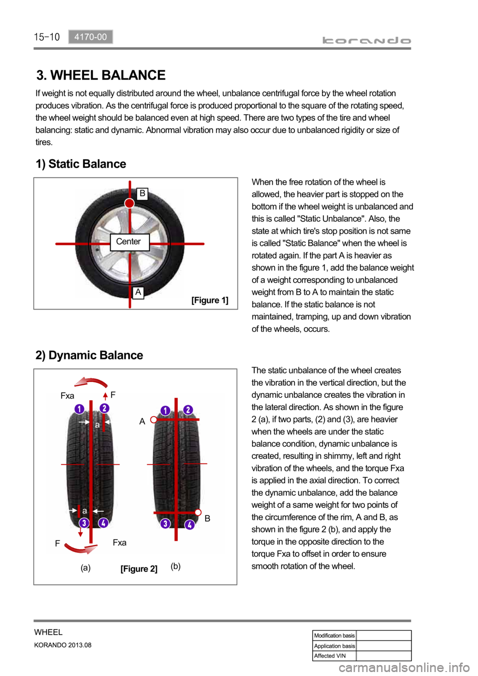
1) Static Balance
When the free rotation of the wheel is
allowed, the heavier part is stopped on the
bottom if the wheel weight is unbalanced and
this is called "Static Unbalance". Also, the
state at which tire's stop position is not same
is called "Static Balance" when the wheel is
rotated again. If the part A is heavier as
shown in the figure 1, add the balance weight
of a weight corresponding to unbalanced
weight from B to A to maintain the static
balance. If the static balance is not
maintained, tramping, up and down vibration
of the wheels, occurs.
2) Dynamic Balance
The static unbalance of the wheel creates
the vibration in the vertical direction, but the
dynamic unbalance creates the vibration in
the lateral direction. As shown in the figure
2 (a), if two parts, (2) and (3), are heavier
when the wheels are under the static
balance condition, dynamic unbalance is
created, resulting in shimmy, left and right
vibration of the wheels, and the torque Fxa
is applied in the axial direction. To correct
the dynamic unbalance, add the balance
weight of a same weight for two points of
the circumference of the rim, A and B, as
shown in the figure 2 (b), and apply the
torque in the opposite direction to the
torque Fxa to offset in order to ensure
smooth rotation of the wheel.
Center
A
B
a
a
Fxa
Fxa F
F
A
B
(a)(b)
[Figure 1]
[Figure 2]
3. WHEEL BALANCE
Page 1163 of 1336
4012-00
Unit Construction
Front sub
frame
Rear sub
frame
(4WD)
Rear sub
frame
(2WD)
1. SPECIFICATION
Body mounting:
4-points bush
Transaxle mounting:
2-points bush
Weight: 22.37 kg 1.
2.
3.
Body mounting:
4-points bush
Axle mounting:
4-points bush
Weight: 16.61 kg 1.
2.
3.
Body mounting:
40 points direct
mounting
Spring link:
Direct mounting
without bracket on
rear cross member
Weight: 12.74 kg 1.
2.
3.
BRKT-ENG MTG RRBRKT-ENG MTG FRT
Page 1164 of 1336
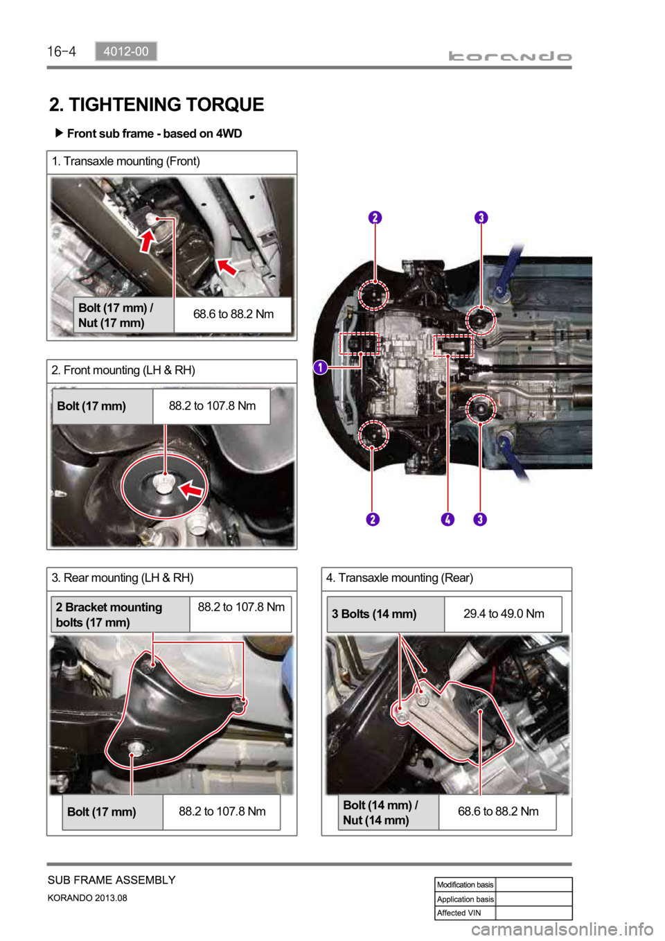
4. Transaxle mounting (Rear)3. Rear mounting (LH & RH)
2. Front mounting (LH & RH)
1. Transaxle mounting (Front)
2. TIGHTENING TORQUE
Bolt (17 mm) /
Nut (17 mm)68.6 to 88.2 Nm
Bolt (17 mm)88.2 to 107.8 Nm
Bolt (17 mm)88.2 to 107.8 Nm
2 Bracket mounting
bolts (17 mm)88.2 to 107.8 Nm
Bolt (14 mm) /
Nut (14 mm)68.6 to 88.2 Nm
3 Bolts (14 mm)29.4 to 49.0 Nm
Front sub frame - based on 4WD
Page 1165 of 1336
4012-00
8. Other connections for rear sub frame (LH &
RH)7. Rear axle mounting
5. Front mounting (LH & RH)
Bolt (17 mm)88.2 to 107.8 Nm
6. Rear mounting (LH & RH)
Bolt (17 mm)88.2 to 107.8 Nm
Rear mounting
bolt (14 mm)68.6 to 88.2 Nm
Upper arm bolt
(17 mm) / Nut (19
mm)98.0 to 117.6 Nm
Lower arm nut/Bolt
(19 mm)98.0 to 117.6 Nm
Rear sub frame - based on 4WD
Rear mounting
bolt (17 mm)107.8 to 127.4 Nm
Page 1166 of 1336
Installation Sectional diagram
1. Front
2. Rear
Mounting bracket Mounting bolt
3. Transaxle mounting (Front)
For manual transaxle For automatic transaxle
(diesel)
4. Transaxle mounting (Rear)
1) Sectional Diagram and Bolts for Front Sub Frame
Mounting nut
29.4 to 39.2 Nm
Bolt9.4 to 39.2 Nm
Page 1167 of 1336
4012-00
2) Sectional Diagram and Bolts for Rear Sub Frame
Installation Sectional structure
1. Front
4WD 2WD
2. Rear
4WD 2WD
3. Rear axle - Front
(4WD)
4. Rear axle - rear
(4WD)
Page 1168 of 1336
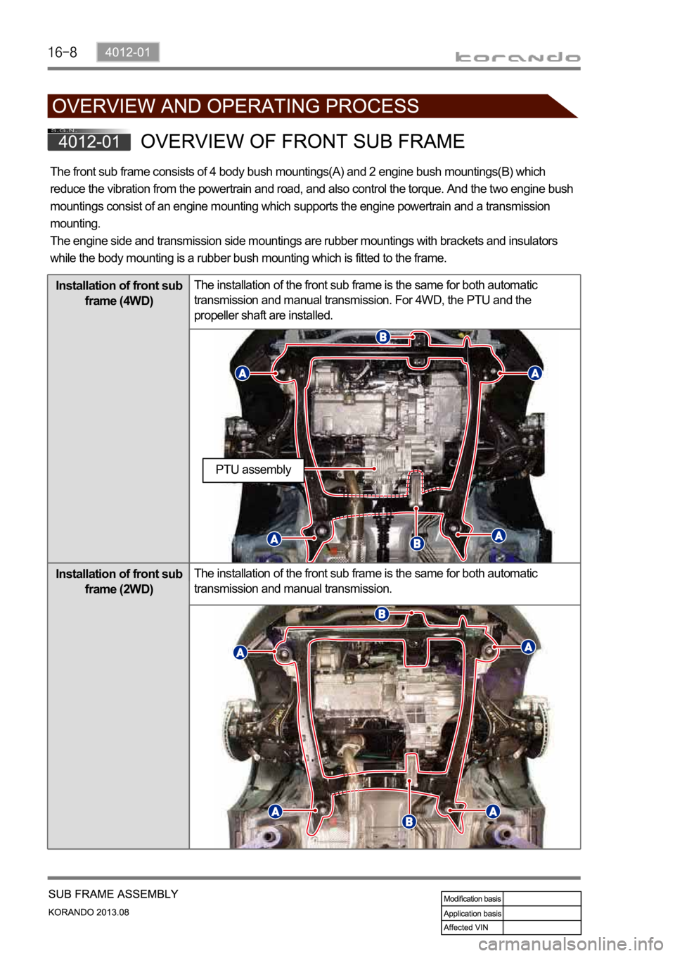
The front sub frame consists of 4 body bush mountings(A) and 2 engine bush mountings(B) which
reduce the vibration from the powertrain and road, and also control the torque. And the two engine bush
mountings consist of an engine mounting which supports the engine powertrain and a transmission
mounting.
The engine side and transmission side mountings are rubber mountings with brackets and insulators
while the body mounting is a rubber bush mounting which is fitted to the frame.
Installation of front sub
frame (4WD)The installation of the front sub frame is the same for both automatic
transmission and manual transmission. For 4WD, the PTU and the
propeller shaft are installed.
Installation of front sub
frame (2WD)The installation of the front sub frame is the same for both automatic
transmission and manual transmission.
PTU assembly
Page 1169 of 1336
4015-01
Installation of rear sub
frame (4WD)The installation of the rear sub frame is the same for both automatic
transmission and manual transmission. For 4WD, the E-coupling, propeller
shaft and rear axle are installed.
Installation of rear sub
frame (2WD) The installation of the rear sub frame is the same for both automatic
transmission and manual transmission.
The rear sub frame system consists of body bush mountings and direct mountings which reduce the
vibration transmitted from the powertrain and road to the vehicle body.
For 4WD, it consists of 4 body mountings (bush mountings) and 2 axle mountings (bush mountings) and
for 2WD, it consists of 4 body mountings (direct mountings).
Page 1170 of 1336
4190-00
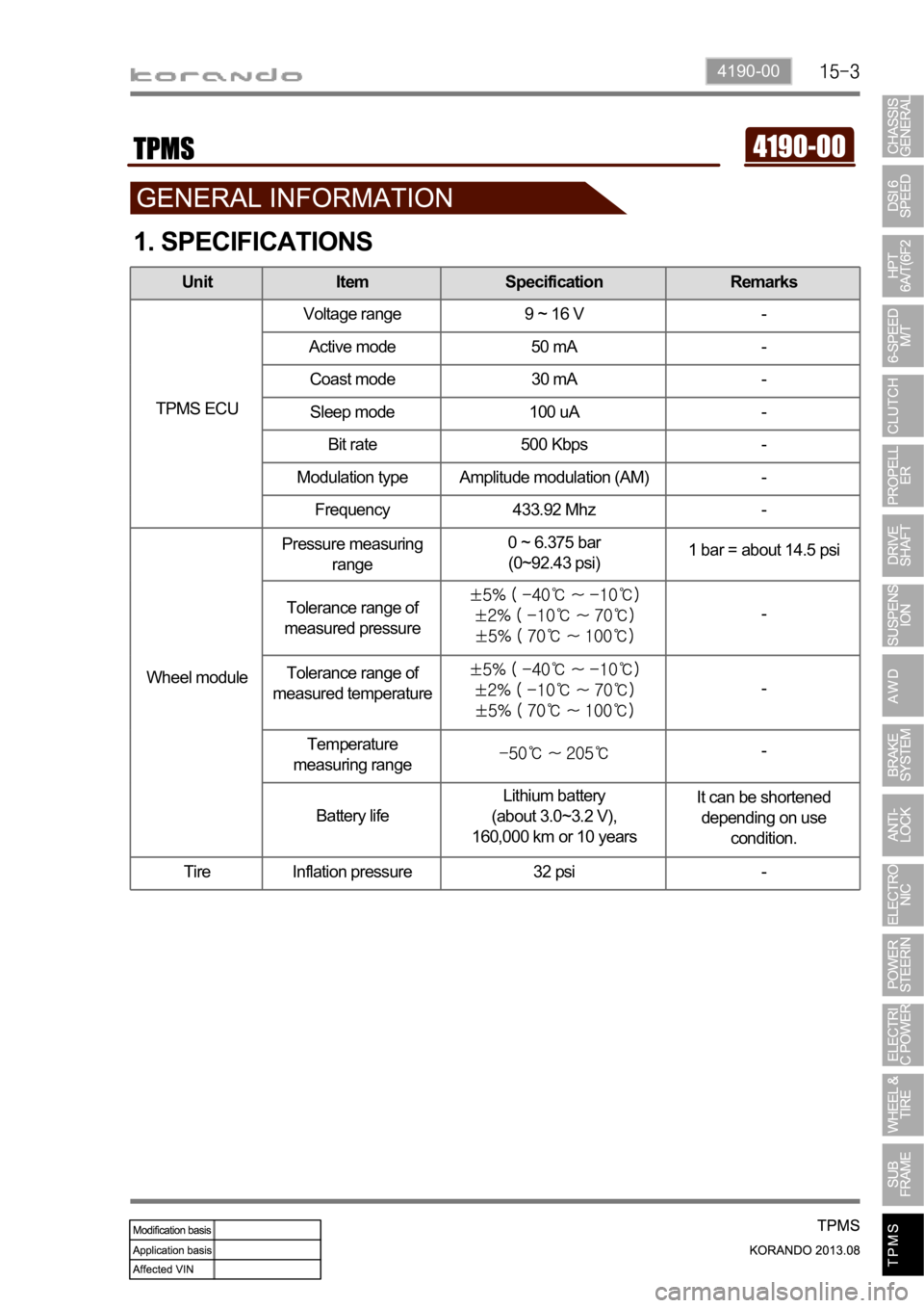
1. SPECIFICATIONS
Unit Item Specification Remarks
TPMS ECUVoltage range 9 ~ 16 V -
Active mode 50 mA -
Coast mode 30 mA -
Sleep mode 100 uA -
Bit rate 500 Kbps -
Modulation type Amplitude modulation (AM) -
Frequency 433.92 Mhz -
Wheel modulePressure measuring
range0 ~ 6.375 bar
(0~92.43 psi)1 bar = about 14.5 psi
Tolerance range of
measured pressure
-
Tolerance range of
measured temperature
-
Temperature
measuring range
-
Battery lifeLithium battery
(about 3.0~3.2 V),
160,000 km or 10 yearsIt can be shortened
depending on use
condition.
Tire Inflation pressure 32 psi -
Trending: height adjustment, diagram, child restraint, spare tire, remove seats, fuse box location, oil dipstick
