SSANGYONG KORANDO 2013 Service Manual
KORANDO 2013
SSANGYONG
SSANGYONG
https://www.carmanualsonline.info/img/67/57503/w960_57503-0.png
SSANGYONG KORANDO 2013 Service Manual
Page 462 of 1336
1130-13
3) Features of DMF
Reduced vibration noise from the powertrain by blocking the torsional vibrations
Enhanced vehicle silence and riding comforts: reduced engine torque fluctuation
Reduced shifting shocks
Smooth acceleration and deceleration -
-
-
-
4) Advantages of DMF
Improved torque response by using 2-stage type spring: Strengthens the torque response in all
ranges (low, medium, and high speed) by applying respective spring constant at each
range.
Stable revolution of the primary and secondary wheel by using planetary gear: Works as auxiliary
damper against spring changes
Less heat generation due to no direct friction against spring surface: Plastic material is covered on the
spring outer surface
Increased durability by using plastic bushing (extends the lifetime of grease) -
-
-
-
Page 463 of 1336
Components
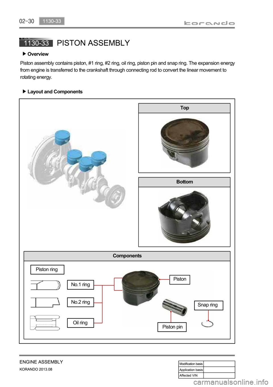
Piston assembly contains piston, #1 ring, #2 ring, oil ring, piston pin and snap ring. The expansion energy
from engine is transferred to the crankshaft through connecting rod to convert the linear movement to
rotating energy.Overview
Layout and Components
Top
Bottom
Oil ring
Piston ring
No.1 ring
Piston pin
No.2 ringSnap ring
Piston
Page 464 of 1336
1130-33
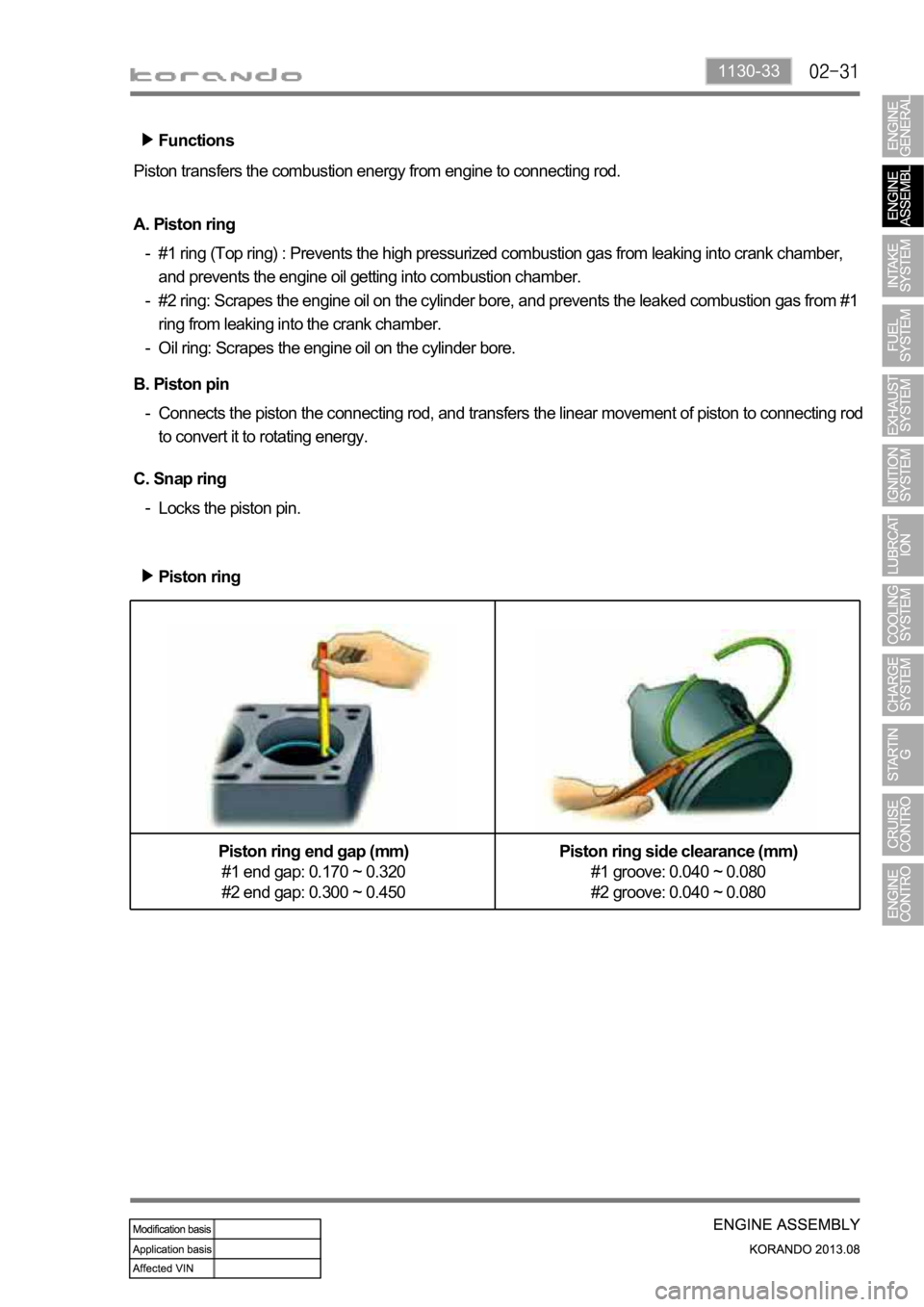
Functions
Piston transfers the combustion energy from engine to connecting rod.
C. Snap ring
Locks the piston pin. - A. Piston ring
#1 ring (Top ring) : Prevents the high pressurized combustion gas from leaking into crank chamber,
and prevents the engine oil getting into combustion chamber.
#2 ring: Scrapes the engine oil on the cylinder bore, and prevents the leaked combustion gas from #1
ring from leaking into the crank chamber.
Oil ring: Scrapes the engine oil on the cylinder bore. -
-
-
B. Piston pin
Connects the piston the connecting rod, and transfers the linear movement of piston to connecting rod
to convert it to rotating energy. -
Piston ring
Piston ring end gap (mm)
#1 end gap: 0.170 ~ 0.320
#2 end gap: 0.300 ~ 0.450Piston ring side clearance (mm)
#1 groove: 0.040 ~ 0.080
#2 groove: 0.040 ~ 0.080
Page 469 of 1336
Bottom of cylinder block Crankshaft sprocket installing surface
Crankshaft lower bearing Crankshaft lower bearing
Selection of crankshaft main bearing
Pin
punch
markColorDiameter of crankshaft
main journal in cylinder
block (mm)
* Blue 62.500 ~ 62.506
** Yellow 62.506 ~ 62.513
*** Red 62.513 ~ 62.519Mark ColorDiameter of
crankshaft main
journal (mm)
B Blue 57.960 ~ 57.965
Y Yellow 57.955 ~ 57.960
R Red 57.950 ~ 57.955
W White 57.945 ~ 57.950
V Violet 57.940 ~ 57.945
Engine
name
Main
journal
bearing
#1 #2 #3 #4 #5
G2 0DF
RRWWR
Page 470 of 1336
1128-01
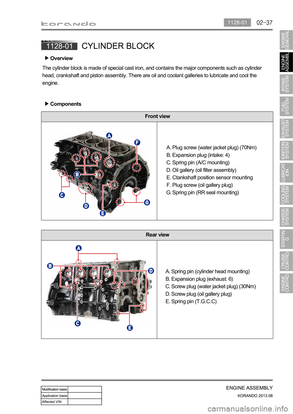
Front view
Rear view
Spring pin (cylinder head mounting)
Expansion plug (exhaust: 6)
Screw plug (water jacket plug) (30Nm)
Screw plug (oil gallery plug)
Spring pin (T.G.C.C) A.
B.
C.
D.
E.
Overview
The cylinder block is made of special cast iron, and contains the major components such as cylinder
head, crankshaft and piston assembly. There are oil and coolant galleries to lubricate and cool the
engine.
Components
Plug screw (water jacket plug) (70Nm)
Expansion plug (intake: 4)
Spring pin (A/C mounting)
Oil gallery (oil filter assembly)
Ctankshaft position sensor mounting
Plug screw (oil gallery plug)
Spring pin (RR seal mounting) A.
B.
C.
D.
E.
F.
G.
Page 471 of 1336
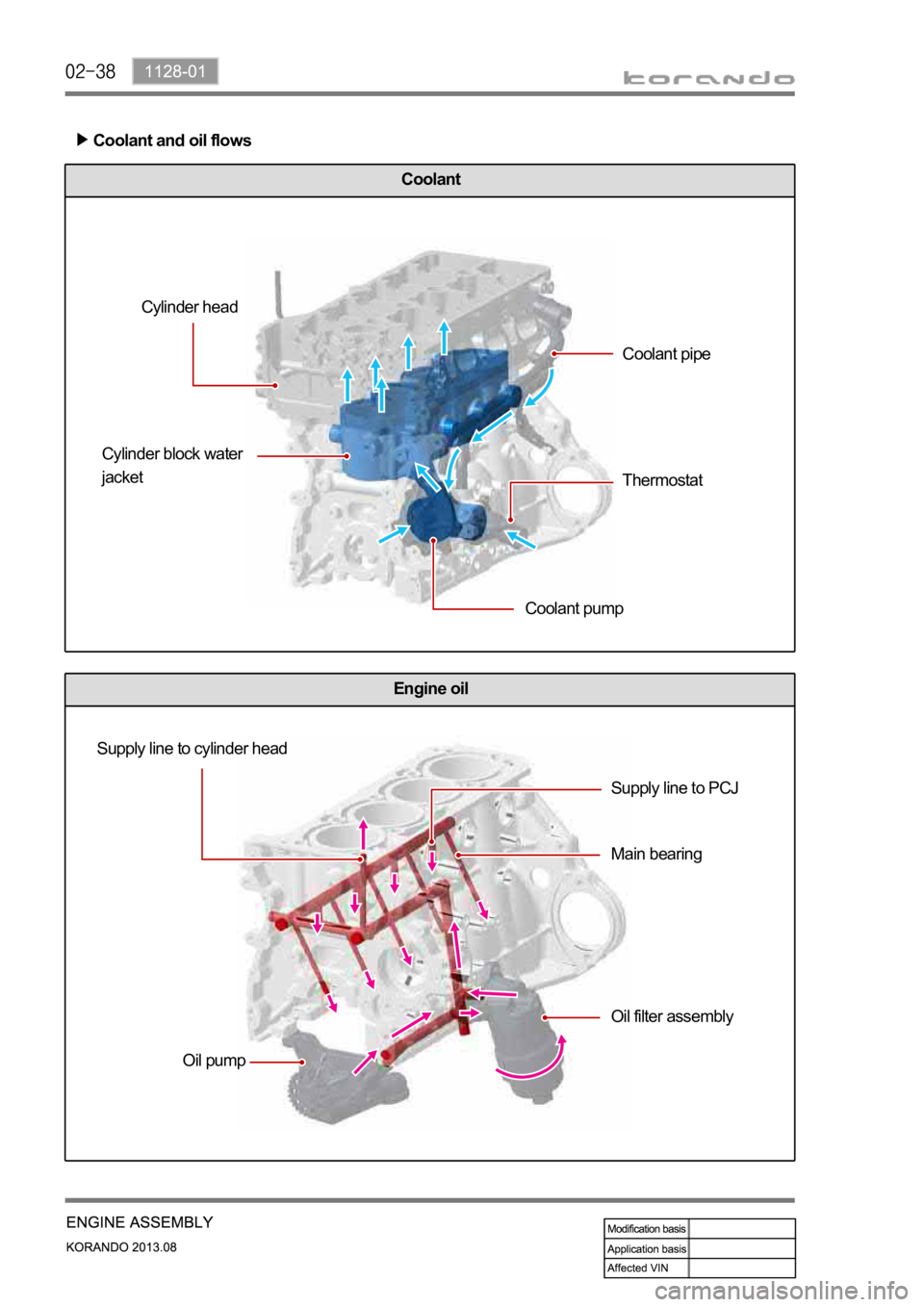
Engine oil
Coolant
Coolant and oil flows
Cylinder head
Cylinder block water
jacket
Coolant pumpCoolant pipe
Thermostat
Supply line to cylinder head
Oil pumpSupply line to PCJ
Main bearing
Oil filter assembly
Page 474 of 1336
0000-00
Air Cleaner Assy
Element Assy
Air Cleaner MTG NO.2
Insulator Collar
Spring Clamp
Resonance Duct
Resonance O-Ring
Air Cleaner MTG NO.1
Air Cleaner MTG Bolt 1.
3.
5.
6.
7.
8.
9.
10.
11.Snorkel Assy
Water Portector
Resonator Assy
RR Fascia MTG Screw Rivet
Bolt
Nut
Screw
Air Cleaner to Engine Hose Assy 12.
13.
14.
17.
18.
19.
20.
21.
Page 475 of 1336
Intake manifold assembly
T-MAP sensorVIS valve
1. OVERVIEW
To improve the engine performance, the VIS system has been introduced in the intake manifold. It
And, to reduce the internal pulsation in the intake manifold, the Runner # 1 and #2 are located in
2. COMPONENTS
VIS solenoid valve
Page 483 of 1336
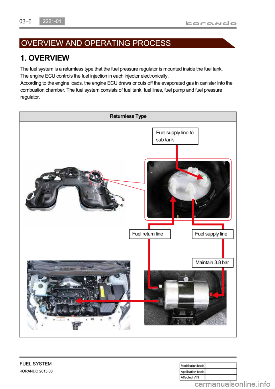
Returnless Type
1. OVERVIEW
The fuel system is a returnless type that the fuel pressure regulator is mounted inside the fuel tank.
The engine ECU controls the fuel injection in each injector electronically.
According to the engine loads, the engine ECU draws or cuts off the evaporated gas in canister into the
combustion chamber. The fuel system consists of fuel tank, fuel lines, fuel pump and fuel pressure
regulator.
Fuel supply line to
sub tank
Fuel return lineFuel supply line
Maintain 3.8 bar
Page 486 of 1336
2221-01
Engine ECU
Engine compartment
InjectorPurge control solenoid
valveFuel rail
Secondary fuel sender
