battery SSANGYONG KORANDO 2013 User Guide
[x] Cancel search | Manufacturer: SSANGYONG, Model Year: 2013, Model line: KORANDO, Model: SSANGYONG KORANDO 2013Pages: 1336, PDF Size: 92.18 MB
Page 312 of 1336
(3) Starting with jumper cable
If the battery is weak or terminated, the battery from another vehicle can be used with jumper cables to
start the engine.
Connecting order
The positive (+) terminal of the discharged battery
The positive (+) terminal of the booster battery
The negative (-) terminal of the booster battery
Connect one end of the other jumper cable to the body of the discharged vehicle, such as the
engine block or a front towing hook. 1.
2.
3.
4.
Starting
Prepare a set of jumper cables.
Place another vehicle that has the same 12 V of power near to the discharged vehicle.
Switch off all electrical accessories for the discharged vehicle.
Apply the parking brake and shift the transaxle to the P position (automatic transaxle) or neutral (N)
position (manual transaxle).
Connect the jumper cables.
Try to start the discharged vehicle while accelerating the engine rpm in the booster vehicle.
Attempt to start the engine with the discharged battery.
After starting the engine, carefully disconnect the jumper cables in the reverse sequence of
connection. 1.
2.
3.
4.
5.
6.
7.
8.
Page 313 of 1336
0000-00
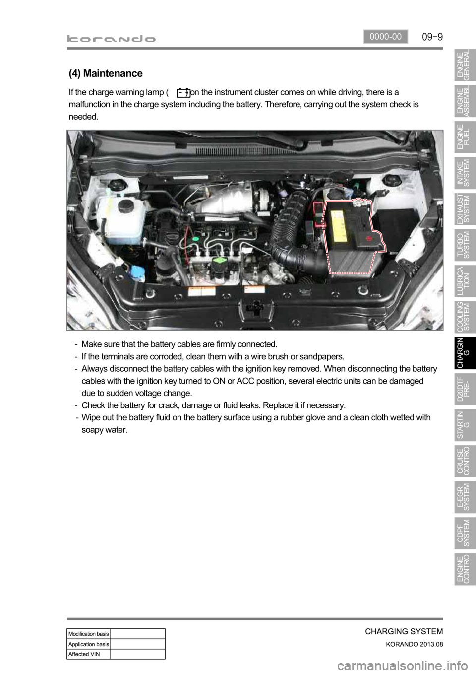
(4) Maintenance
Make sure that the battery cables are firmly connected.
If the terminals are corroded, clean them with a wire brush or sandpapers.
Always disconnect the battery cables with the ignition key removed. When disconnecting the battery
cables with the ignition key turned to ON or ACC position, several electric units can be damaged
due to sudden voltage change.
Check the battery for crack, damage or fluid leaks. Replace it if necessary.
Wipe out the battery fluid on the battery surface using a rubber glove and a clean cloth wetted with
soapy water. -
-
-
-
-
If the charge warning lamp ( ) on the instrument cluster comes on while driving, there is a
malfunction in the charge system including the battery. Therefore, carrying out the system check is
needed.
Page 314 of 1336

Battery
It converts the chemical energy to the
electrical energy and supplies power to the
corresponding electric units when starting
the engine.Alternator
The alternator charges the battery and
supplies power to each electric unit by
converting the mechanical energy to the
electrical energy.
1. SYSTEM DESCRIPTION
1) Overview
The charge system is designed to supply electrical energy to the vehicle while driving, and supplies a
constant direct current voltage by converting mechanical rotational movement to electrical energy.
The voltage regulator on the back of the alternator controls the generated voltage in all rotating ranges
and adjusts the system voltage according to the electric load and ambient temperature change.
2) System Layout (Locations)
Page 315 of 1336
0000-00
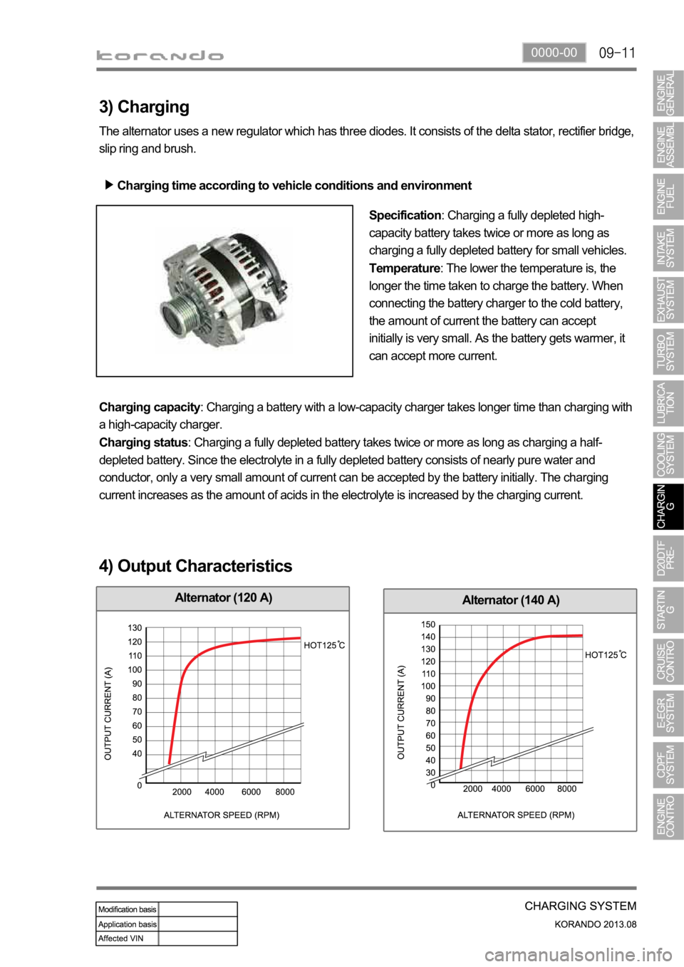
Alternator (140 A)Alternator (120 A)
3) Charging
The alternator uses a new regulator which has three diodes. It consists of the delta stator, rectifier bridge,
slip ring and brush.
Charging time according to vehicle conditions and environment
Specification: Charging a fully depleted high-
capacity battery takes twice or more as long as
charging a fully depleted battery for small vehicles.
Temperature: The lower the temperature is, the
longer the time taken to charge the battery. When
connecting the battery charger to the cold battery,
the amount of current the battery can accept
initially is very small. As the battery gets warmer, it
can accept more current.
Charging capacity: Charging a battery with a low-capacity charger takes longer time than charging with
a high-capacity charger.
Charging status: Charging a fully depleted battery takes twice or more as long as charging a half-
depleted battery. Since the electrolyte in a fully depleted battery consists of nearly pure water and
conductor, only a very small amount of current can be accepted by the battery initially. The charging
current increases as the amount of acids in the electrolyte is increased by the charging current.
4) Output Characteristics
Page 328 of 1336

1413-00
(3) Operating Steps
Pre-Glow: Step 1
If normal communication with the ECU is established 2 seconds after the power is supplied to the IGN
terminal from the battery, the GCU supplies the battery power to raise the temperature of the glow plug
- The time for pre-heating is controlled by the ECU.
If the input voltage (VB) is 11.5 V or less, GCU supplies the battery voltage for preheating time (T1).
If the input voltage (VB) is greater than 11.5 V, GCU supplies the voltage of 11.5 V for preheating time
(T1). -
-
The preheating time may vary according to the conditions.
Input voltage
VB (V)Pre-heating time T1
(sec)
6 8.27
7 5.8
8 4.1
9 3.15
10 2.4
11 1.95
1.9
Page 333 of 1336
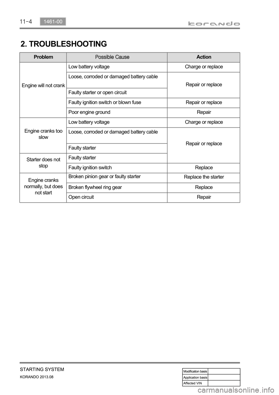
2. TROUBLESHOOTING
ProblemAction
Engine will not crankLow battery voltage Charge or replace
Loose, corroded or damaged battery cable
Repair or replace
Faulty starter or open circuit
Faulty ignition switch or blown fuse Repair or replace
Poor engine ground Repair
Engine cranks too
slowLow battery voltage Charge or replace
Loose, corroded or damaged battery cable
Repair or replace
Faulty starter
Starter does not
stopFaulty starter
Faulty ignition switch Replace
Engine cranks
normally, but does
not startBroken pinion gear or faulty starter
Replace the starter
Broken flywheel ring gear Replace
Open circuit Repair
Page 374 of 1336
0000-00
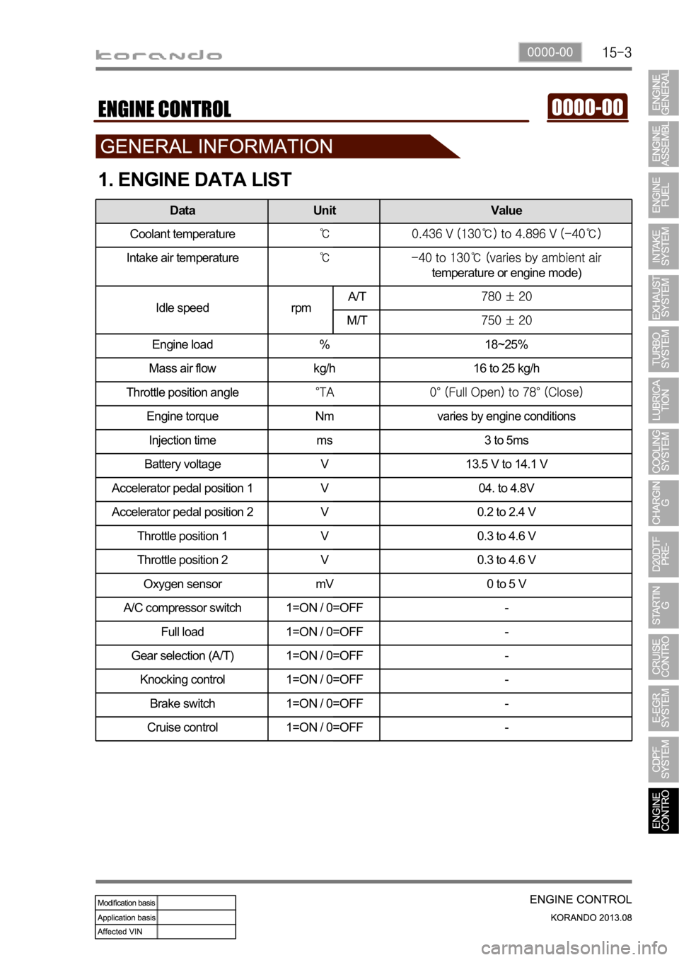
1. ENGINE DATA LIST
Data Unit Value
Coolant temperature
Intake air temperature
temperature or engine mode)
Idle speed rpmA/T
M/T
Engine load % 18~25%
Mass air flow kg/h 16 to 25 kg/h
Throttle position angle
Engine torque Nm varies by engine conditions
Injection time ms 3 to 5ms
Battery voltage V 13.5 V to 14.1 V
Accelerator pedal position 1 V 04. to 4.8V
Accelerator pedal position 2 V 0.2 to 2.4 V
Throttle position 1 V 0.3 to 4.6 V
Throttle position 2 V 0.3 to 4.6 V
Oxygen sensor mV 0 to 5 V
A/C compressor switch 1=ON / 0=OFF -
Full load 1=ON / 0=OFF -
Gear selection (A/T) 1=ON / 0=OFF -
Knocking control 1=ON / 0=OFF -
Brake switch 1=ON / 0=OFF -
Cruise control 1=ON / 0=OFF -
Page 385 of 1336
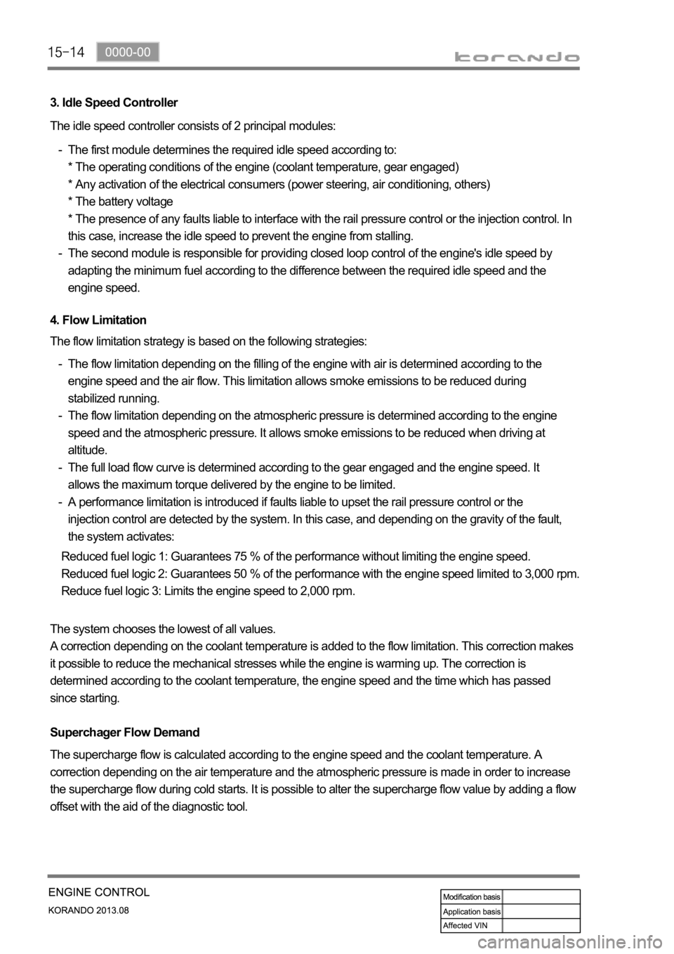
3. Idle Speed Controller
The idle speed controller consists of 2 principal modules:
The first module determines the required idle speed according to:
* The operating conditions of the engine (coolant temperature, gear engaged)
* Any activation of the electrical consumers (power steering, air conditioning, others)
* The battery voltage
* The presence of any faults liable to interface with the rail pressure control or the injection control. In
this case, increase the idle speed to prevent the engine from stalling.
The second module is responsible for providing closed loop control of the engine's idle speed by
adapting the minimum fuel according to the difference between the required idle speed and the
engine speed. -
-
4. Flow Limitation
The flow limitation strategy is based on the following strategies:
The flow limitation depending on the filling of the engine with air is determined according to the
engine speed and the air flow. This limitation allows smoke emissions to be reduced during
stabilized running.
The flow limitation depending on the atmospheric pressure is determined according to the engine
speed and the atmospheric pressure. It allows smoke emissions to be reduced when driving at
altitude.
The full load flow curve is determined according to the gear engaged and the engine speed. It
allows the maximum torque delivered by the engine to be limited.
A performance limitation is introduced if faults liable to upset the rail pressure control or the
injection control are detected by the system. In this case, and depending on the gravity of the fault,
the system activates: -
-
-
-
Reduced fuel logic 1: Guarantees 75 % of the performance without limiting the engine speed.
Reduced fuel logic 2: Guarantees 50 % of the performance with the engine speed limited to 3,000 rpm.
Reduce fuel logic 3: Limits the engine speed to 2,000 rpm.
The system chooses the lowest of all values.
A correction depending on the coolant temperature is added to the flow limitation. This correction makes
it possible to reduce the mechanical stresses while the engine is warming up. The correction is
determined according to the coolant temperature, the engine speed and the time which has passed
since starting.
Superchager Flow Demand
The supercharge flow is calculated according to the engine speed and the coolant temperature. A
correction depending on the air temperature and the atmospheric pressure is made in order to increase
the supercharge flow during cold starts. It is possible to alter the supercharge flow value by adding a flow
offset with the aid of the diagnostic tool.
Page 408 of 1336
0000-00
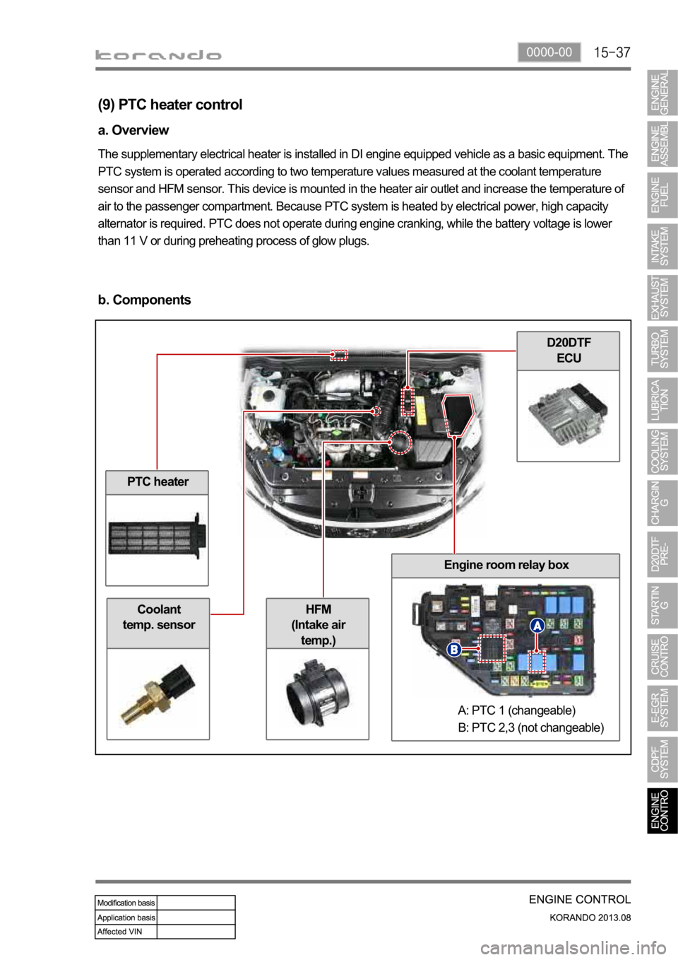
PTC heater
Coolant
temp. sensor
D20DTF
ECU
Engine room relay box
HFM
(Intake air
temp.)
(9) PTC heater control
a. Overview
The supplementary electrical heater is installed in DI engine equipped vehicle as a basic equipment. The
PTC system is operated according to two temperature values measured at the coolant temperature
sensor and HFM sensor. This device is mounted in the heater air outlet and increase the temperature of
air to the passenger compartment. Because PTC system is heated by electrical power, high capacity
alternator is required. PTC does not operate during engine cranking, while the battery voltage is lower
than 11 V or during preheating process of glow plugs.
b. Components
A: PTC 1 (changeable)
B: PTC 2,3 (not changeable)
Page 410 of 1336

0000-00
d. Control conditions
Operation Operating condition PTC Heater
HI
(PTC2)
PTC HI ON
LO
(PTC1)
PTC LO ON
Stop- A/C blower switch OFF
- Defective ambient air temperature sensor
(including open or short circuit)
- Engine cranking
- Low battery voltage (below 11V)
- During pre-glow process (glow indicator ON)
Operation diagram for PTC heater LO (step 2)