SSANGYONG KORANDO 2013 Workshop Manual
KORANDO 2013
SSANGYONG
SSANGYONG
https://www.carmanualsonline.info/img/67/57503/w960_57503-0.png
SSANGYONG KORANDO 2013 Workshop Manual
Page 603 of 1336
0000-00
Inspection
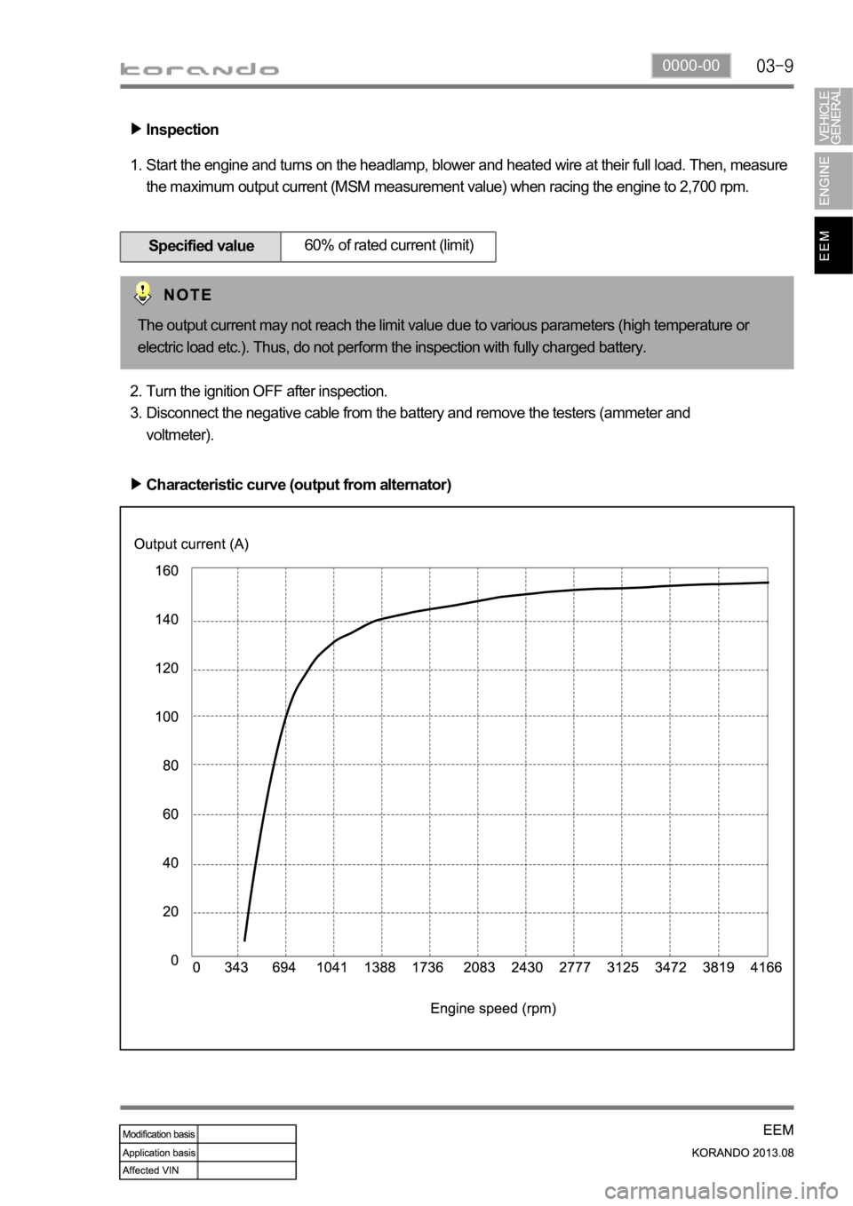
Start the engine and turns on the headlamp, blower and heated wire at their full load. Then, measure
the maximum output current (MSM measurement value) when racing the engine to 2,700 rpm. 1.
Specified value60% of rated current (limit)
Turn the ignition OFF after inspection.
Disconnect the negative cable from the battery and remove the testers (ammeter and
voltmeter). 2.
3.
Characteristic curve (output from alternator)
The output current may not reach the limit value due to various parameters (high temperature or
electric load etc.). Thus, do not perform the inspection with fully charged battery.
Page 605 of 1336
0000-00
Inspection
Measure the current while removing the fuses one by one. If the current drops sharply when a certain
fuse is removed, inspect the affected circuit. 1.
Specified valuebelow 0.05A
6. INSPECTION - DARK CURRENT
Perform the basic inspection. -
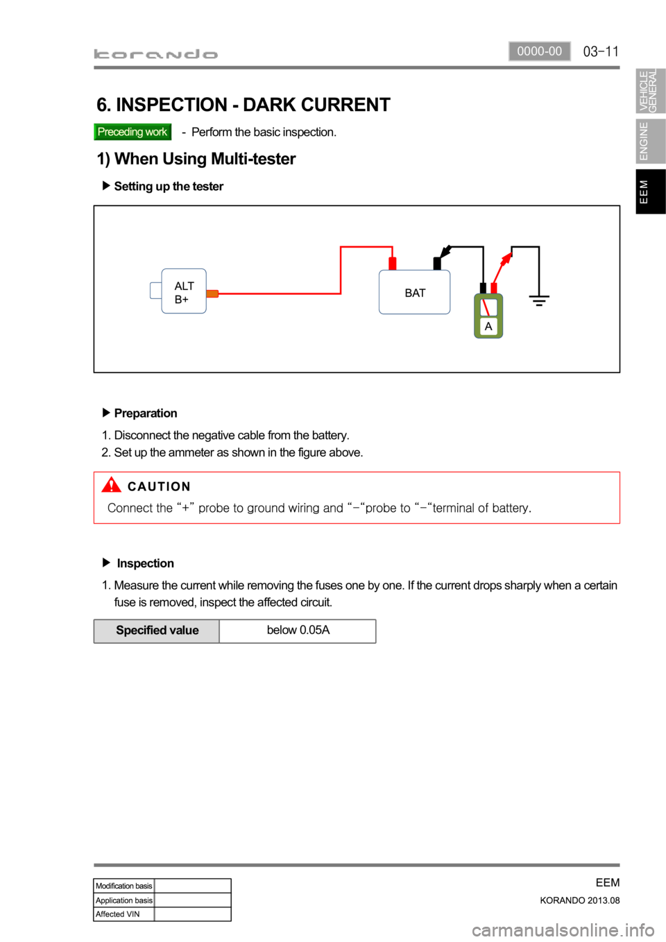
Setting up the tester
Preparation
Disconnect the negative cable from the battery.
Set up the ammeter as shown in the figure above. 1.
2.
1) When Using Multi-tester
Page 606 of 1336
Specified valuebelow 0.05A
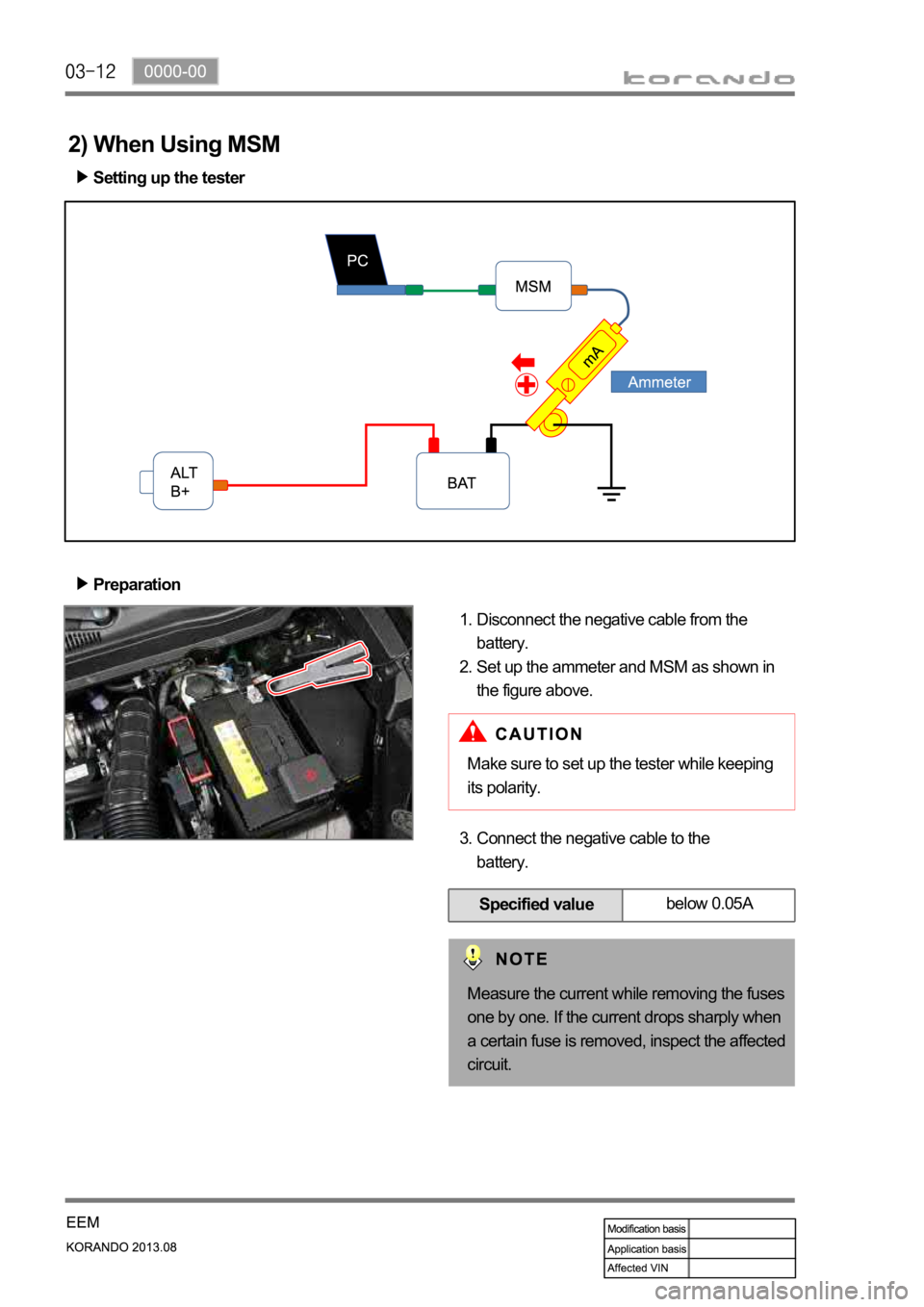
Setting up the tester
Preparation
Disconnect the negative cable from the
battery.
Set up the ammeter and MSM as shown in
the figure above. 1.
2.
2) When Using MSM
Connect the negative cable to the
battery. 3.
Make sure to set up the tester while keeping
its polarity.
Measure the current while removing the fuses
one by one. If the current drops sharply when
a certain fuse is removed, inspect the affected
circuit.
Page 607 of 1336
0000-00
Specified
valueover 11V: Normal
9 ~ 11V: Charging required
below: 9V: Over discharged,
battery replacement required
7. INSPECTION - BATTERY
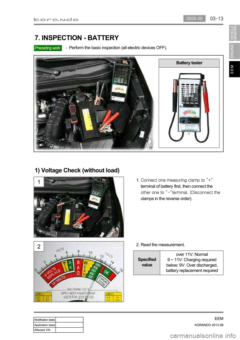
Perform the basic inspection (all electric devices OFF). -
Battery tester
1) Voltage Check (without load)
terminal of battery first, then connect the
clamps in the reverse order). 1.
Read the measurement. 2.
Page 608 of 1336
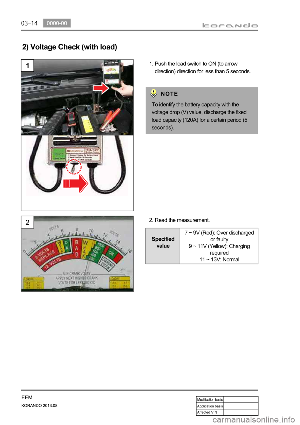
2) Voltage Check (with load)
1Push the load switch to ON (to arrow
direction) direction for less than 5 seconds. 1.
Read the measurement. 2.
Specified
value7 ~ 9V (Red): Over discharged
or faulty
9 ~ 11V (Yellow): Charging
required
11 ~ 13V: Normal
To identify the battery capacity with the
voltage drop (V) value, discharge the fixed
load capacity (120A) for a certain period (5
seconds).
Page 610 of 1336
1. LAYOUT
D20DTF(Low CO2) D20DTF
ECUBattery sensor (EBS)
Alternator (ALT)
Meter cluster (charge
warning lamp)
Page 611 of 1336
0000-00
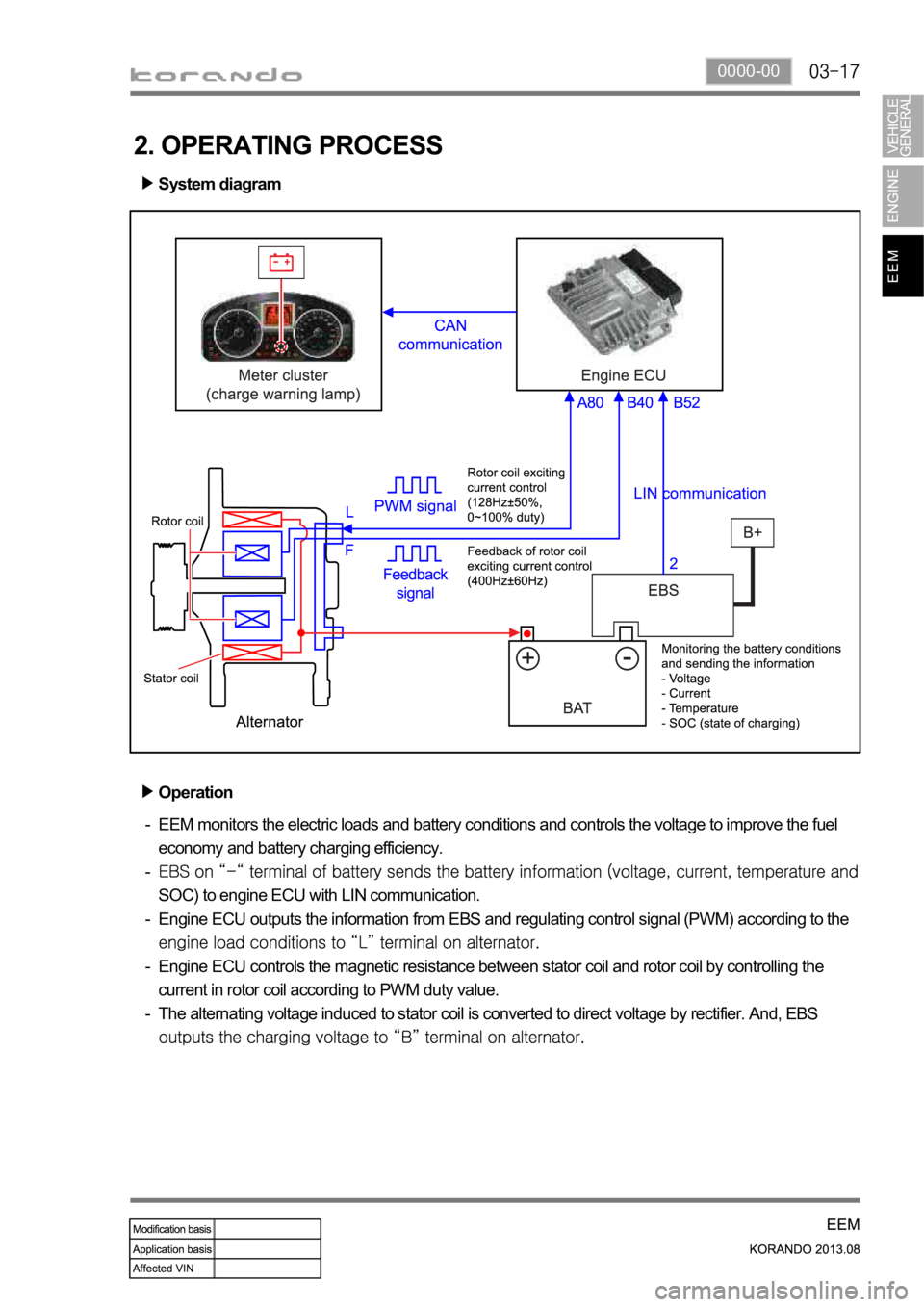
2. OPERATING PROCESS
System diagram
Operation
EEM monitors the electric loads and battery conditions and controls the voltage to improve the fuel
economy and battery charging efficiency.
SOC) to engine ECU with LIN communication.
Engine ECU outputs the information from EBS and regulating control signal (PWM) according to the
Engine ECU controls the magnetic resistance between stator coil and rotor coil by controlling the
current in rotor coil according to PWM duty value.
The alternating voltage induced to stator coil is converted to direct voltage by rectifier. And, EBS
-
-
-
-
-
Page 612 of 1336
Operation of charge warning lamp
ECU checks the generating voltage from alternator and circuit conditions and sends the warning lamp ON
signal to meter cluster through CAN line.Basic control logic according to the driving conditions
Engine ECU determines the engine loads according to the fuel injection volume and engine speed. It
charges the battery by increasing the generating voltage during deceleration. To improve the fuel
economy by reducing the alternator load during acceleration, engine ECU decreases the generating
voltage and consumes the battery voltage.
Page 629 of 1336
8410-00
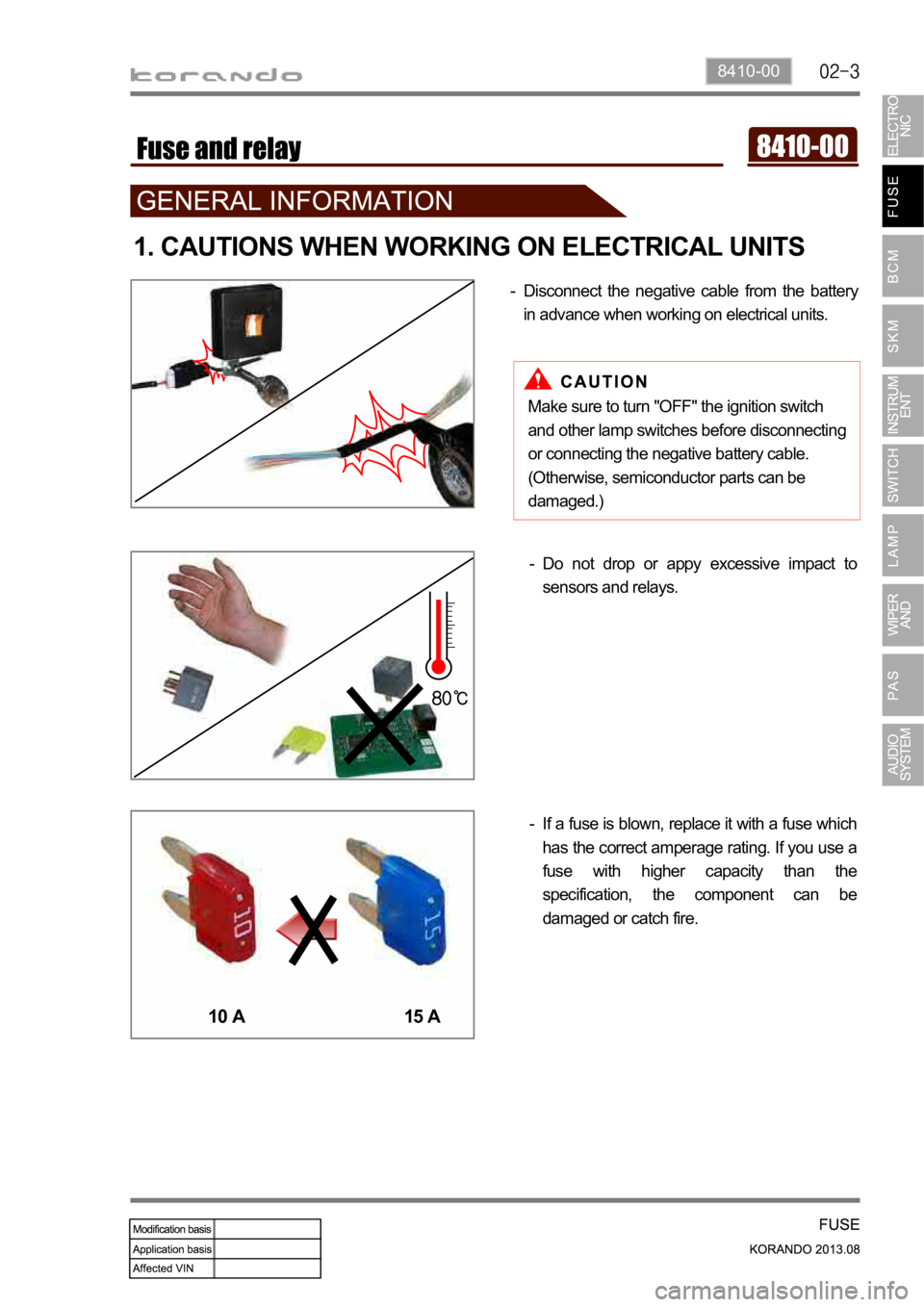
1. CAUTIONS WHEN WORKING ON ELECTRICAL UNITS
Disconnect the negative cable from the battery
in advance when working on electrical units. -
If a fuse is blown, replace it with a fuse which
has the correct amperage rating. If you use a
fuse with higher capacity than the
specification, the component can be
damaged or catch fire. -Do not drop or appy excessive impact to
sensors and relays. -
10 A 15 A
Make sure to turn "OFF" the ignition switch
and other lamp switches before disconnecting
or connecting the negative battery cable.
(Otherwise, semiconductor parts can be
damaged.)
Page 636 of 1336
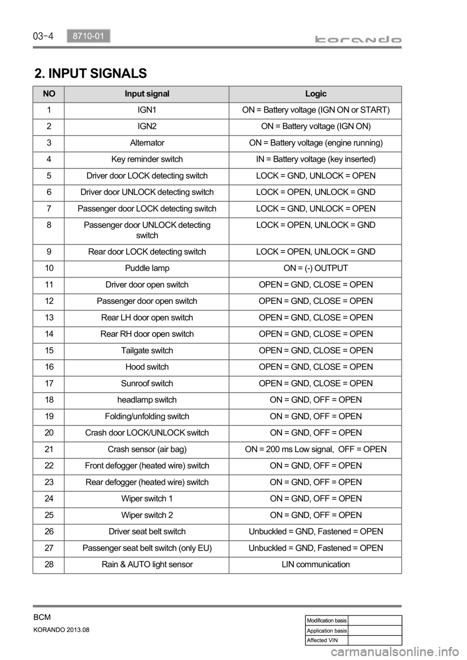
2. INPUT SIGNALS
NO Input signal Logic
1 IGN1 ON = Battery voltage (IGN ON or START)
2 IGN2 ON = Battery voltage (IGN ON)
3 Alternator ON = Battery voltage (engine running)
4 Key reminder switch IN = Battery voltage (key inserted)
5 Driver door LOCK detecting switch LOCK = GND, UNLOCK = OPEN
6 Driver door UNLOCK detecting switch LOCK = OPEN, UNLOCK = GND
7 Passenger door LOCK detecting switch LOCK = GND, UNLOCK = OPEN
8 Passenger door UNLOCK detecting
switchLOCK = OPEN, UNLOCK = GND
9 Rear door LOCK detecting switch LOCK = OPEN, UNLOCK = GND
10 Puddle lamp ON = (-) OUTPUT
11 Driver door open switch OPEN = GND, CLOSE = OPEN
12 Passenger door open switch OPEN = GND, CLOSE = OPEN
13 Rear LH door open switch OPEN = GND, CLOSE = OPEN
14 Rear RH door open switch OPEN = GND, CLOSE = OPEN
15 Tailgate switch OPEN = GND, CLOSE = OPEN
16 Hood switch OPEN = GND, CLOSE = OPEN
17 Sunroof switch OPEN = GND, CLOSE = OPEN
18 headlamp switch ON = GND, OFF = OPEN
19 Folding/unfolding switch ON = GND, OFF = OPEN
20 Crash door LOCK/UNLOCK switch ON = GND, OFF = OPEN
21 Crash sensor (air bag) ON = 200 ms Low signal, OFF = OPEN
22 Front defogger (heated wire) switch ON = GND, OFF = OPEN
23 Rear defogger (heated wire) switch ON = GND, OFF = OPEN
24 Wiper switch 1 ON = GND, OFF = OPEN
25 Wiper switch 2 ON = GND, OFF = OPEN
26 Driver seat belt switch Unbuckled = GND, Fastened = OPEN
27 Passenger seat belt switch (only EU) Unbuckled = GND, Fastened = OPEN
28 Rain & AUTO light sensor LIN communication
