battery SSANGYONG KORANDO 2013 Owner's Guide
[x] Cancel search | Manufacturer: SSANGYONG, Model Year: 2013, Model line: KORANDO, Model: SSANGYONG KORANDO 2013Pages: 1336, PDF Size: 92.18 MB
Page 533 of 1336
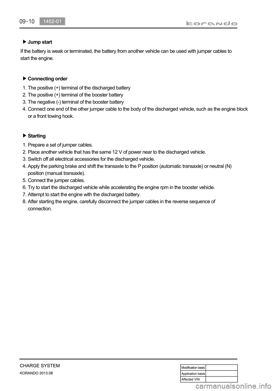
Jump start
If the battery is weak or terminated, the battery from another vehicle can be used with jumper cables to
start the engine.
Connecting order
The positive (+) terminal of the discharged battery
The positive (+) terminal of the booster battery
The negative (-) terminal of the booster battery
Connect one end of the other jumper cable to the body of the discharged vehicle, such as the engine block
or a front towing hook. 1.
2.
3.
4.
Starting
Prepare a set of jumper cables.
Place another vehicle that has the same 12 V of power near to the discharged vehicle.
Switch off all electrical accessories for the discharged vehicle.
Apply the parking brake and shift the transaxle to the P position (automatic transaxle) or neutral (N)
position (manual transaxle).
Connect the jumper cables.
Try to start the discharged vehicle while accelerating the engine rpm in the booster vehicle.
Attempt to start the engine with the discharged battery.
After starting the engine, carefully disconnect the jumper cables in the reverse sequence of
connection. 1.
2.
3.
4.
5.
6.
7.
8.
Page 534 of 1336
1452-01
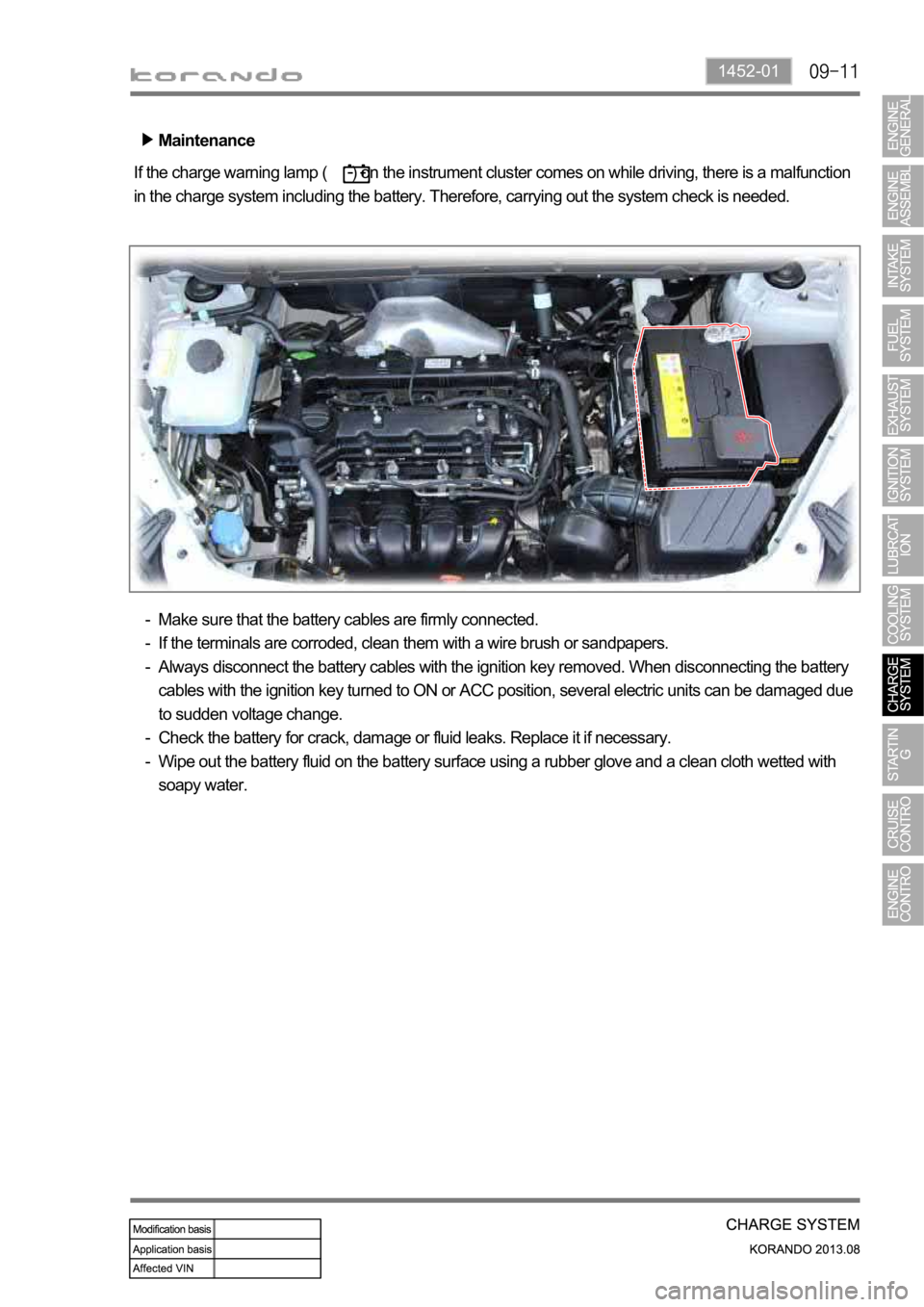
Maintenance
If the charge warning lamp ( ) on the instrument cluster comes on while driving, there is a malfunction
in the charge system including the battery. Therefore, carrying out the system check is needed.
Make sure that the battery cables are firmly connected.
If the terminals are corroded, clean them with a wire brush or sandpapers.
Always disconnect the battery cables with the ignition key removed. When disconnecting the battery
cables with the ignition key turned to ON or ACC position, several electric units can be damaged due
to sudden voltage change.
Check the battery for crack, damage or fluid leaks. Replace it if necessary.
Wipe out the battery fluid on the battery surface using a rubber glove and a clean cloth wetted with
soapy water. -
-
-
-
-
Page 535 of 1336

Battery
It converts the chemical energy to the
electrical energy and supplies power to the
corresponding electric units when starting the
engine.
1. OVERVIEW
The charge system is designed to supply electrical energy to the vehicle while driving, and supplies a
constant direct current voltage by converting mechanical rotational movement to electrical energy. The
voltage regulator on the back of the alternator controls the generated voltage in all rotating ranges and
adjusts the system voltage according to the electric load and ambient temperature change.
Body ground
B+ wiringAlternator
The alternator charges the battery and
supplies power to each electric unit by
converting the mechanical energy to the
electrical energy.
Page 541 of 1336
1462-01
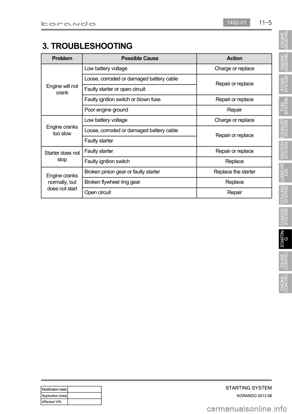
3. TROUBLESHOOTING
Problem Possible Cause Action
Engine will not
crankLow battery voltage Charge or replace
Loose, corroded or damaged battery cable
Repair or replace
Faulty starter or open circuit
Faulty ignition switch or blown fuse Repair or replace
Poor engine ground Repair
Engine cranks
too slowLow battery voltage Charge or replace
Loose, corroded or damaged battery cable
Repair or replace
Faulty starter
Starter does not
stopFaulty starter Repair or replace
Faulty ignition switch Replace
Engine cranks
normally, but
does not startBroken pinion gear or faulty starter Replace the starter
Broken flywheel ring gear Replace
Open circuit Repair
Page 557 of 1336
1490-00
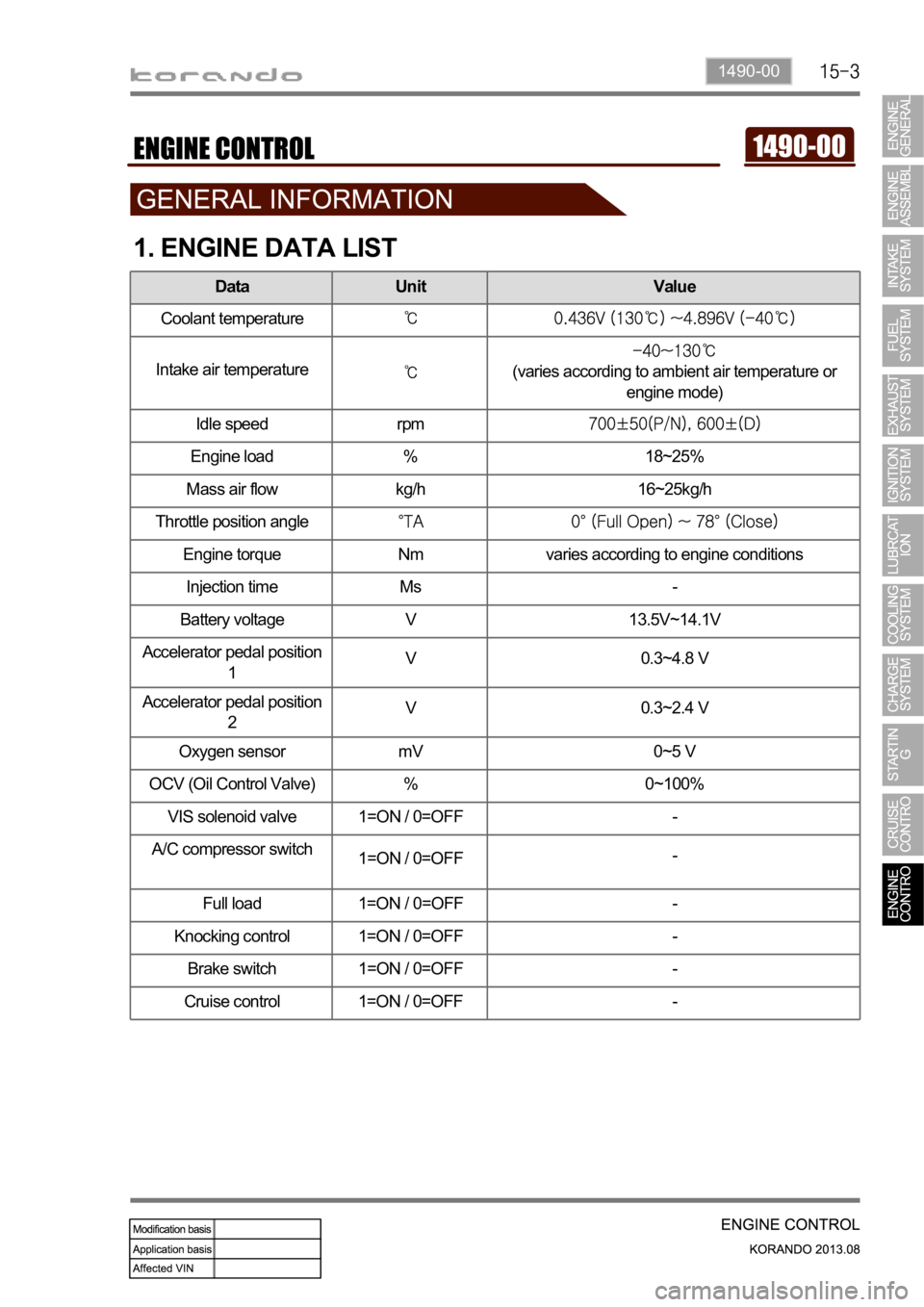
1. ENGINE DATA LIST
Data Unit Value
Coolant temperature
Intake air temperature(varies according to ambient air temperature or
engine mode)
Idle speed rpm
Engine load % 18~25%
Mass air flow kg/h 16~25kg/h
Throttle position angle
Engine torque Nm varies according to engine conditions
Injection time Ms -
Battery voltage V 13.5V~14.1V
Accelerator pedal position
1V 0.3~4.8 V
Accelerator pedal position
2V 0.3~2.4 V
Oxygen sensor mV 0~5 V
OCV (Oil Control Valve) % 0~100%
VIS solenoid valve 1=ON / 0=OFF -
A/C compressor switch
1=ON / 0=OFF-
Full load 1=ON / 0=OFF -
Knocking control 1=ON / 0=OFF -
Brake switch 1=ON / 0=OFF -
Cruise control 1=ON / 0=OFF -
Page 597 of 1336
0000-00
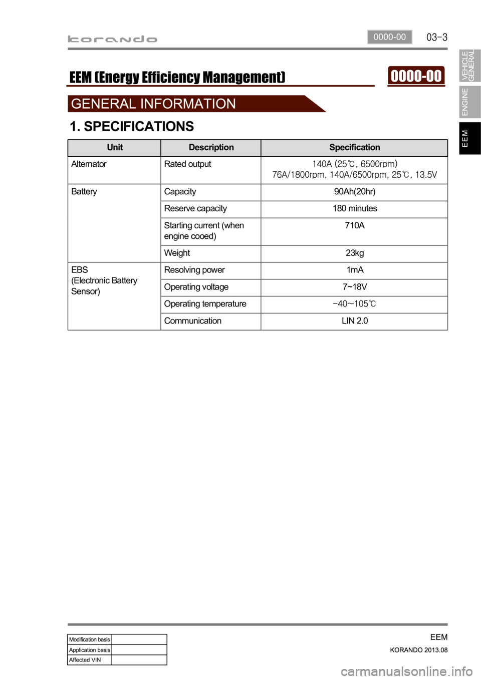
1. SPECIFICATIONS
Alternator Rated output
Battery Capacity 90Ah(20hr)
Reserve capacity 180 minutes
Starting current (when
engine cooed)710A
Weight 23kg
EBS
(Electronic Battery
Sensor)Resolving power 1mA
Operating voltage 7~18V
Operating temperature
Communication LIN 2.0
Unit Description Specification
Page 598 of 1336
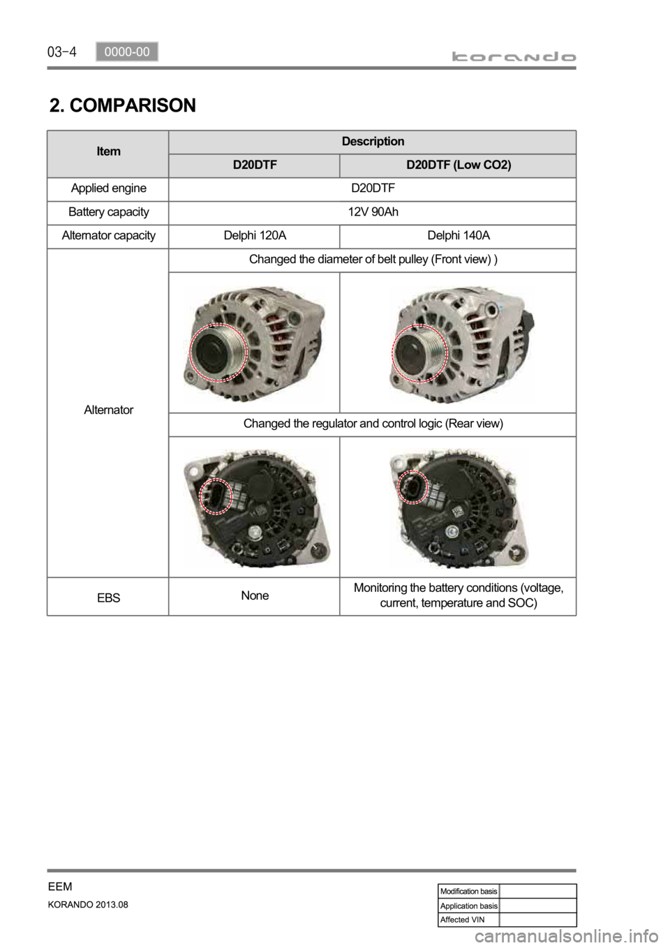
ItemDescription
D20DTF D20DTF (Low CO2)
Applied engine D20DTF
Battery capacity 12V 90Ah
Alternator capacity Delphi 120A Delphi 140A
AlternatorChanged the diameter of belt pulley (Front view) )
Changed the regulator and control logic (Rear view)
EBSNoneMonitoring the battery conditions (voltage,
current, temperature and SOC)
2. COMPARISON
Page 599 of 1336

0000-00
3. BASIC INSPECTION
1) Battery Terminal
Make sure the terminal connections are
securely tightened. If the terminals are
corroded, clean them or replace the battery. -
* Cleaning
Remove the corrosion or dirt with a wire brush
or sand paper, and then wash out with
lukewarm soapy water.
2) Measuring the Voltage Drop
Measuring at battery terminal
Measure the voltage between battery
terminal (+. -) and wiring clamp. -
Specified valuebelow 0.3V
If the terminals are corroded, clean and
retightening them. If the specified tightening
torque cannot be kept, replace the clamp.
Terminal (+)
Terminal (-)
Terminal (+): 4 ~ 5 Nm
Page 600 of 1336

Measuring at (-) wiring
Measure the voltage between battery wiring
and body ground. -
Specified valuebelow 0.3V
If the voltage is out of the specified value,
check the wiring mounting bolt for corrosion
and looseness. If there is a poor contact due
to corrosion or paint, wipe out the contact area
and retighten it.
Wiring mounting bolt to body
ground (-): 17 Nm
Measuring the battery voltage
Stop the engine and wait for 20 minutes.
Measure the voltage between terminal (+)
and terminal (-) with the ignition switch OFF
and all electric devices OFF. -
Specified valueover 12V
Page 601 of 1336

0000-00
Measuring the voltage drop between lines
Measure the voltage drop between alternator B+ and battery B+. -
Specified valuebelow 0.3V
If the value is out of the specified value, check the terminal and clamp for looseness.
Checking the charge warning lamp
Check if the charge warning lamp goes out.
If the charge warning lamp does not go off, inspect the electric circuit.
Start the engine and check if the charge warning lamp keeps off. 1.
2.
-
3.