engine SSANGYONG KORANDO 2013 User Guide
[x] Cancel search | Manufacturer: SSANGYONG, Model Year: 2013, Model line: KORANDO, Model: SSANGYONG KORANDO 2013Pages: 1336, PDF Size: 92.18 MB
Page 194 of 1336
0000-00
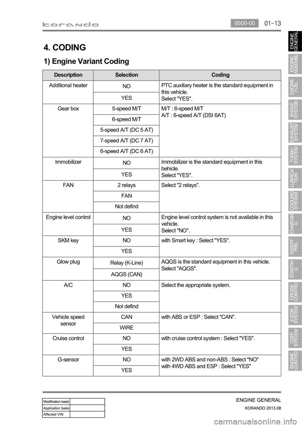
4. CODING
1) Engine Variant Coding
Description Selection Coding
Additional heater
NOPTC auxiliary heater is the standard equipment in
this vehicle.
Select "YES". YES
Gear box 5-speed M/T M/T : 6-speed M/T
A/T : 6-speed A/T (DSI 6AT)
6-speed M/T
5-speed A/T (DC 5 AT)
7-speed A/T (DC 7 AT)
6-speed A/T (DC 6 AT)
Immobilizer
NOImmobilizer is the standard equipment in this
behicle.
Select "YES". YES
FAN 2 relays Select "2 relays".
FAN
Not defind
Engine level control
NOEngine level control system is not available in this
vehicle.
Select "NO". YES
SKM key NO with Smart key : Select "YES".
YES
Glow plug
Relay (K-Line)AQGS is the standard equipment in this vehicle.
Select "AQGS".
AQGS (CAN)
A/C NO Select the appropriate system.
YES
Not defind
Vehicle speed
sensorCAN with ABS or ESP : Select "CAN".
WIRE
Cruise control NO with cruise control system : Select "YES".
YES
G-sensor NO with 2WD ABS and non-ABS : Select "NO"
with 4WD ABS and ESP : Select "YES"
YES
Page 195 of 1336
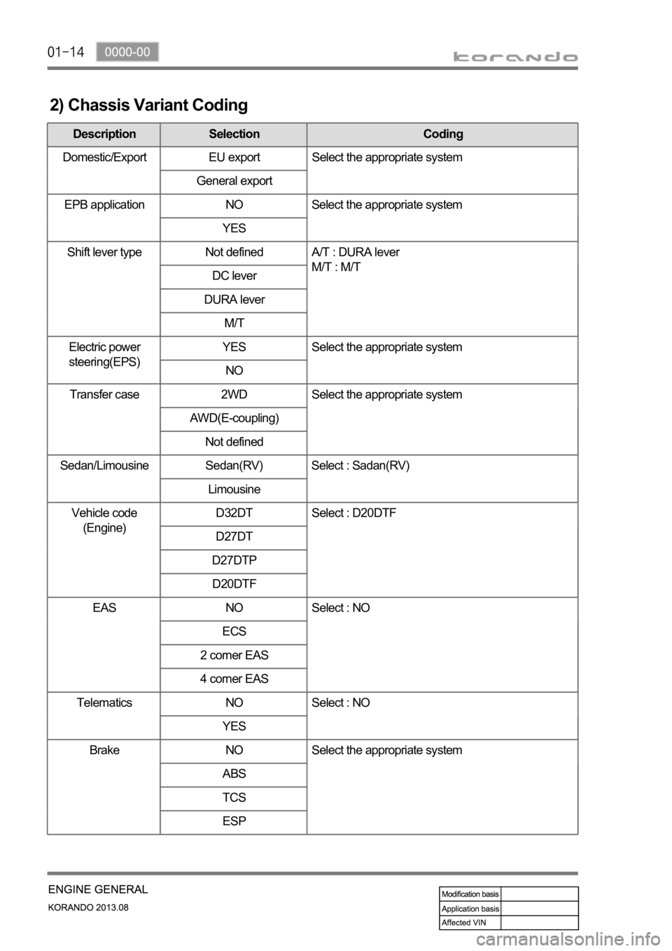
2) Chassis Variant Coding
Description Selection Coding
Domestic/Export EU export Select the appropriate system
General export
EPB application NO Select the appropriate system
YES
Shift lever type Not defined A/T : DURA lever
M/T : M/T
DC lever
DURA lever
M/T
Electric power
steering(EPS)YES Select the appropriate system
NO
Transfer case 2WD Select the appropriate system
AWD(E-coupling)
Not defined
Sedan/Limousine Sedan(RV) Select : Sadan(RV)
Limousine
Vehicle code
(Engine)D32DT Select : D20DTF
D27DT
D27DTP
D20DTF
EAS NO Select : NO
ECS
2 corner EAS
4 corner EAS
Telematics NO Select : NO
YES
Brake NO Select the appropriate system
ABS
TCS
ESP
Page 199 of 1336

0000-00
Engine Mount
1900-00 Mounting Assembly RH
1900-00 Front Mounting Assembly
1900-00 Rear Mounting Assembly
- Changed appearance of right-hand mounting assembly and its rubber for enhanced NVH
performance
NVH performance
* The mounting appearance has been changed, but work procedure is same as the old one.
2/4WD
2WD 4WD 2WD 4WD
2WD 4WD
Page 207 of 1336
0000-00
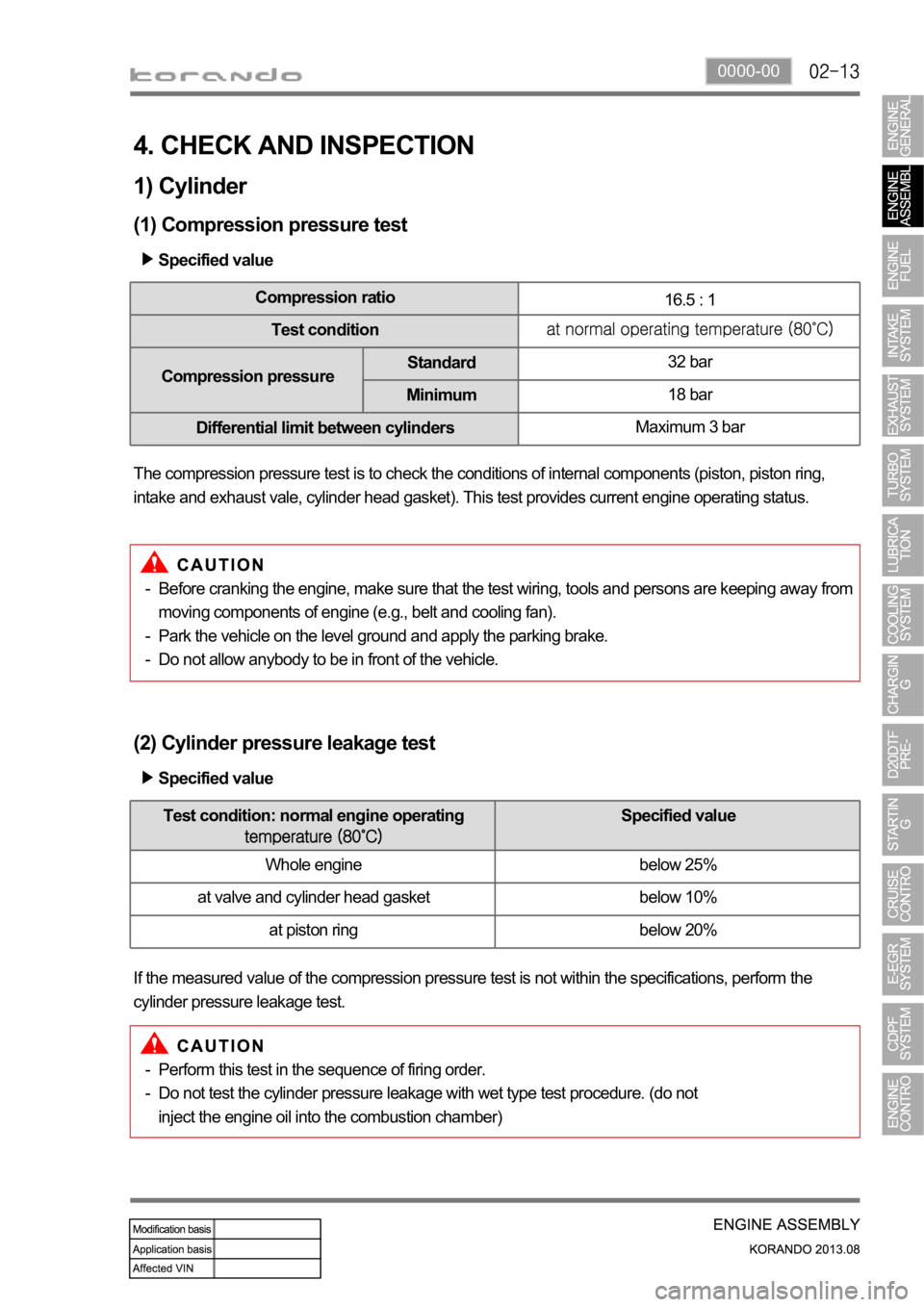
4. CHECK AND INSPECTION
1) Cylinder
(1) Compression pressure test
Specified value
Compression ratio
16.5 : 1
Test condition
Compression pressureStandard32 bar
Minimum18 bar
Differential limit between cylindersMaximum 3 bar
The compression pressure test is to check the conditions of internal components (piston, piston ring,
intake and exhaust vale, cylinder head gasket). This test provides current engine operating status.
Before cranking the engine, make sure that the test wiring, tools and persons are keeping away from
moving components of engine (e.g., belt and cooling fan).
Park the vehicle on the level ground and apply the parking brake.
Do not allow anybody to be in front of the vehicle. -
-
-
(2) Cylinder pressure leakage test
If the measured value of the compression pressure test is not within the specifications, perform the
cylinder pressure leakage test.Specified value
Perform this test in the sequence of firing order.
Do not test the cylinder pressure leakage with wet type test procedure. (do not
inject the engine oil into the combustion chamber) -
-
Test condition: normal engine operating Specified value
Whole engine below 25%
at valve and cylinder head gasket below 10%
at piston ring below 20%
Page 210 of 1336
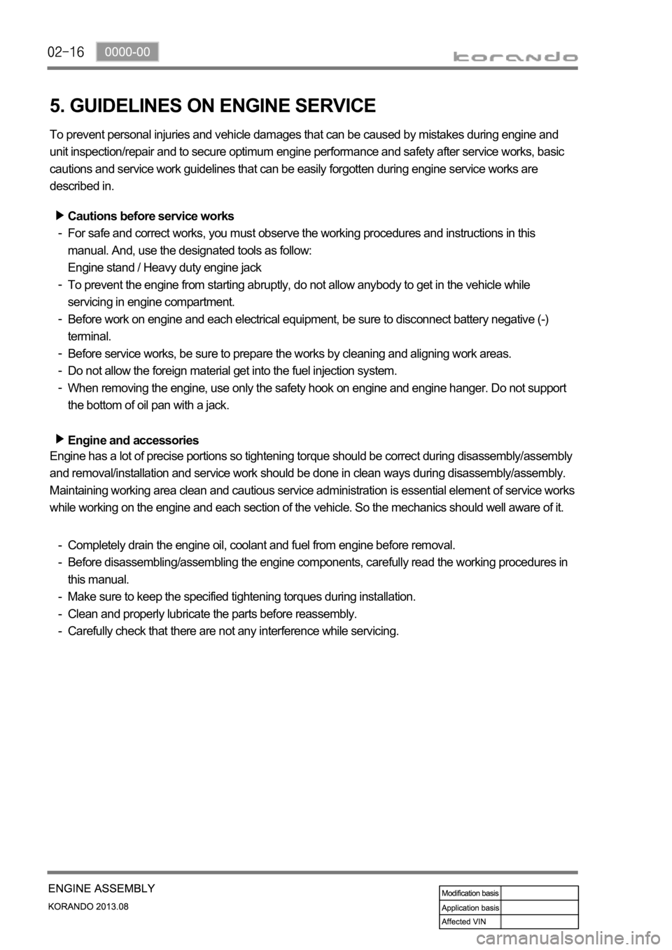
5. GUIDELINES ON ENGINE SERVICE
To prevent personal injuries and vehicle damages that can be caused by mistakes during engine and
unit inspection/repair and to secure optimum engine performance and safety after service works, basic
cautions and service work guidelines that can be easily forgotten during engine service works are
described in.
Cautions before service works
For safe and correct works, you must observe the working procedures and instructions in this
manual. And, use the designated tools as follow:
Engine stand / Heavy duty engine jack
To prevent the engine from starting abruptly, do not allow anybody to get in the vehicle while
servicing in engine compartment.
Before work on engine and each electrical equipment, be sure to disconnect battery negative (-)
terminal.
Before service works, be sure to prepare the works by cleaning and aligning work areas.
Do not allow the foreign material get into the fuel injection system.
When removing the engine, use only the safety hook on engine and engine hanger. Do not support
the bottom of oil pan with a jack.
Engine and accessories
-
-
-
-
-
-
Completely drain the engine oil, coolant and fuel from engine before removal.
Before disassembling/assembling the engine components, carefully read the working procedures in
this manual.
Make sure to keep the specified tightening torques during installation.
Clean and properly lubricate the parts before reassembly.
Carefully check that there are not any interference while servicing. -
-
-
-
- Engine has a lot of precise portions so tightening torque should be correct during disassembly/assembly
and removal/installation and service work should be done in clean ways during disassembly/assembly.
Maintaining working area clean and cautious service administration is essential element of service works
while working on the engine and each section of the vehicle. So the mechanics should well aware of it.
Page 211 of 1336
0000-00
Electrical equipment
Electric devices should be handled more carefully.
Currently, the engine has a lot of electric devices. there could be poor engine performance, incomplete
combustion and other abnormal symptoms due to short circuit or poor contact.
Before work on engine and each electrical equipment, be sure to disconnect battery negative (-)
terminal.
When replacing the electric device, use only genuine part and check the conditions of connections
and grounds. Loosened connection or ground make cause a fire and personal injury. -
-Fuel and lubrication system
Do not allow the fluid and engine oil to make contact with the body paintwork and hoses.
If work on the fluid system such as fuel and oil, working area should be well ventilated and smoking
should be prohibited.
Gasket or seal on the fuel/lubrication system should be replaced with new ones and bolts and nuts
should be tightened as specified.
After removal/installation works, be sure to check whether there is leak on the connecting section. -
-
-
-
If fine dust or foreign material enters into DI engine's fuel system, there can be serious damages in HP
pump and injectors. Thus, be sure to plug the inlets of removed fuel line components with cap and
protect removed parts not to be contaminated with dirt. (Refer to cleanness in this manual while working
on DI engine fuel system)
Page 213 of 1336
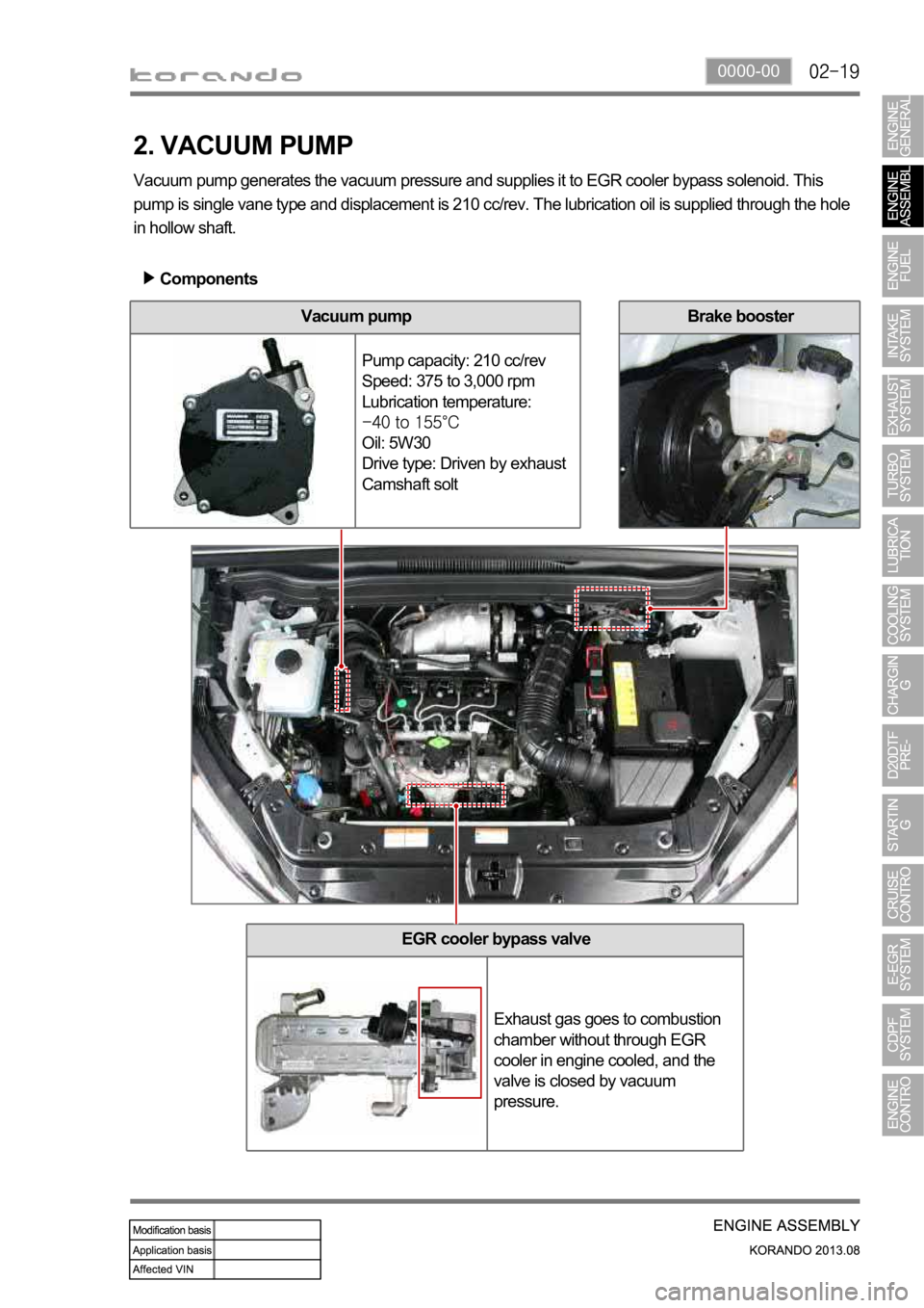
0000-00
EGR cooler bypass valve
Exhaust gas goes to combustion
chamber without through EGR
cooler in engine cooled, and the
valve is closed by vacuum
pressure.
2. VACUUM PUMP
Vacuum pump generates the vacuum pressure and supplies it to EGR cooler bypass solenoid. This
pump is single vane type and displacement is 210 cc/rev. The lubrication oil is supplied through the hole
in hollow shaft.
Components
Vacuum pump
Pump capacity: 210 cc/rev
Speed: 375 to 3,000 rpm
Lubrication temperature:
Oil: 5W30
Drive type: Driven by exhaust
Camshaft solt
Brake booster
Page 214 of 1336
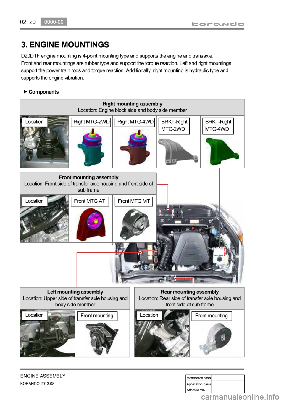
Front mounting assembly
Location: Front side of transfer axle housing and front side of
sub frame
Right mounting assembly
Location: Engine block side and body side member
Rear mounting assembly
Location: Rear side of transfer axle housing and
front side of sub frame
3. ENGINE MOUNTINGS
D20DTF engine mounting is 4-point mounting type and supports the engine and transaxle.
Front and rear mountings are rubber type and support the torque reaction. Left and right mountings
support the power train rods and torque reaction. Additionally, right mounting is hydraulic type and
supports the engine vibration.
Components
Left mounting assembly
Location: Upper side of transfer axle housing and
body side member
LocationFront mounting
Location
BRKT-Right
MTG-4WD
LocationFront mounting
BRKT-Right
MTG-2WD
Front MTG MTFront MTG AT
LocationRight MTG-4WDRight MTG-2WD
Page 219 of 1336
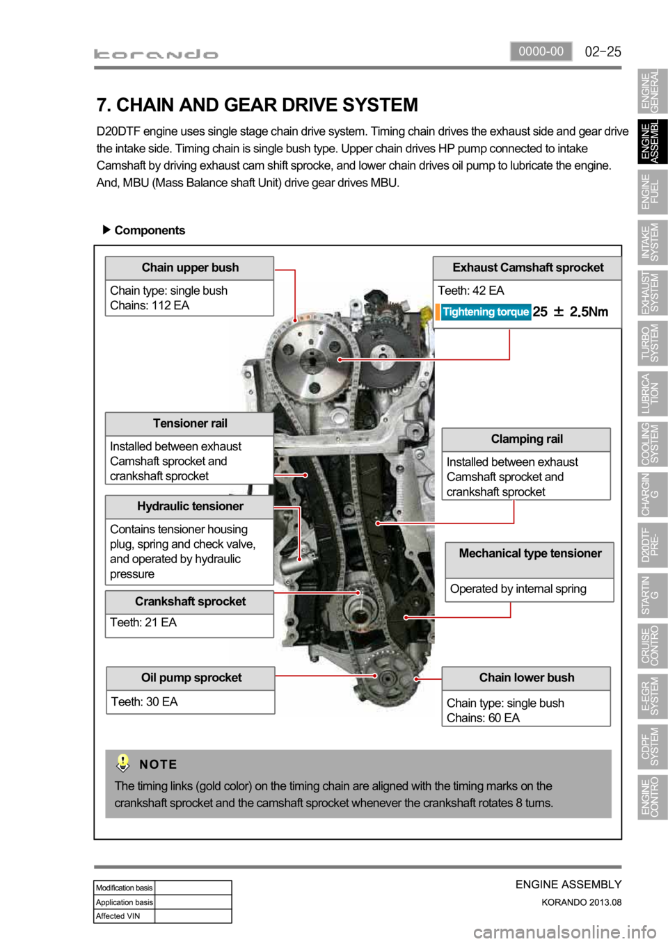
0000-00
Chain upper bush
Chain type: single bush
Chains: 112 EA
Hydraulic tensioner
Contains tensioner housing
plug, spring and check valve,
and operated by hydraulic
pressure
Exhaust Camshaft sprocket
Teeth: 42 EA
Clamping rail
Installed between exhaust
Camshaft sprocket and
crankshaft sprocket
7. CHAIN AND GEAR DRIVE SYSTEM
D20DTF engine uses single stage chain drive system. Timing chain drives the exhaust side and gear drive
the intake side. Timing chain is single bush type. Upper chain drives HP pump connected to intake
Camshaft by driving exhaust cam shift sprocke, and lower chain drives oil pump to lubricate the engine.
And, MBU (Mass Balance shaft Unit) drive gear drives MBU.
Components
Chain lower bush
Chain type: single bush
Chains: 60 EA
Mechanical type tensioner
Operated by internal spring
The timing links (gold color) on the timing chain are aligned with the timing marks on the
crankshaft sprocket and the camshaft sprocket whenever the crankshaft rotates 8 turns.
Oil pump sprocket
Teeth: 30 EA
Tensioner rail
Installed between exhaust
Camshaft sprocket and
crankshaft sprocket
Crankshaft sprocket
Teeth: 21 EA
Page 223 of 1336
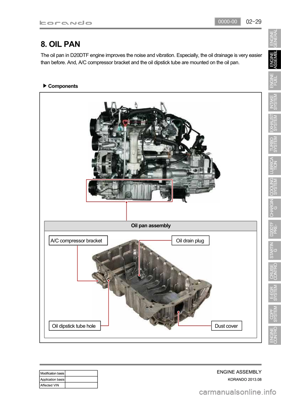
0000-00
Oil pan assembly
8. OIL PAN
The oil pan in D20DTF engine improves the noise and vibration. Especially, the oil drainage is very easier
than before. And, A/C compressor bracket and the oil dipstick tube are mounted on the oil pan.
Components
Oil drain plug
Dust cover
A/C compressor bracket
Oil dipstick tube hole