change wheel SSANGYONG KORANDO 2013 Owner's Manual
[x] Cancel search | Manufacturer: SSANGYONG, Model Year: 2013, Model line: KORANDO, Model: SSANGYONG KORANDO 2013Pages: 1336, PDF Size: 92.18 MB
Page 1131 of 1336
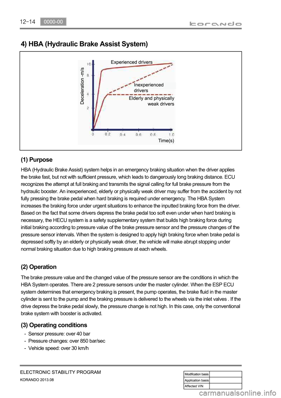
4) HBA (Hydraulic Brake Assist System)
(1) Purpose
HBA (Hydraulic Brake Assist) system helps in an emergency braking situation when the driver applies
the brake fast, but not with sufficient pressure, which leads to dangerously long braking distance. ECU
recognizes the attempt at full braking and transmits the signal calling for full brake pressure from the
hydraulic booster. An inexperienced, elderly or physically weak driver may suffer from the accident by not
fully pressing the brake pedal when hard braking is required under emergency. The HBA System
increases the braking force under urgent situations to enhance the inputted braking force from the driver.
Based on the fact that some drivers depress the brake pedal too soft even under when hard braking is
necessary, the HECU system is a safety supplementary system that builds high braking force during
initial braking according to pressure value of the brake pressure sensor and the pressure changes of the
pressure sensor intervals. When the system is designed to apply high braking force when brake pedal is
depressed softly by an elderly or physically weak driver, the vehicle will make abrupt stopping under
normal braking situation due to high braking pressure at each wheels.
(2) Operation
The brake pressure value and the changed value of the pressure sensor are the conditions in which the
HBA System operates. There are 2 pressure sensors under the master cylinder. When the ESP ECU
system determines that emergency braking is present, the pump operates, the brake fluid in the master
cylinder is sent to the pump and the braking pressure is delivered to the wheels via the inlet valves . If the
drive depress the brake pedal slowly, the pressure change is not high. In this case, only the conventional
brake system with booster is activated.
(3) Operating conditions
Sensor pressure: over 40 bar
Pressure changes: over 850 bar/sec
Vehicle speed: over 30 km/h -
-
-
Page 1132 of 1336
0000-00
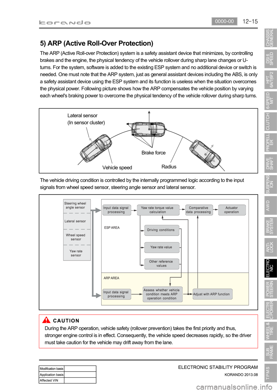
5) ARP (Active Roll-Over Protection)
The ARP (Active Roll-over Protection) system is a safety assistant device that minimizes, by controlling
brakes and the engine, the physical tendency of the vehicle rollover during sharp lane changes or U-
turns. For the system, software is added to the existing ESP system and no additional device or switch is
needed. One must note that the ARP system, just as general assistant devices including the ABS, is only
a safety assistant device using the ESP system and its function is useless when the situation overcomes
the physical power. Following picture shows how the ARP compensates the vehicle position by varying
each wheel's braking power to overcome the physical tendency of the vehicle rollover during sharp turns.
Lateral sensor
(In sensor cluster)
Vehicle speedBrake force
Radius
The vehicle driving condition is controlled by the internally programmed logic according to the input
signals from wheel speed sensor, steering angle sensor and lateral sensor.
During the ARP operation, vehicle safety (rollover prevention) takes the first priority and thus,
stronger engine control is in effect. Consequently, the vehicle speed decreases rapidly, so the driver
must take caution for the vehicle may drift away from the lane.
Page 1137 of 1336
Circuit description
When compared to the vehicle equipped with ABS/EBD only, the internal hydraulic circuit has a
normally-open separation valve and a shuttle valve in primary circuit and in secondary circuit.
When the vehicle brakes are not applied during engine running or when applying the non-ABS operating
brakes, the normally-open separation valve and the inlet valve are open, whereas the normally-closed
shuttle valve and the outlet valve are closed.
When the ESP system is operating, the normally-open separation valve will be closed by the solenoid
valve operation and the hydraulic circuit will be established by the shuttle valve. Then, the inlet and outlet
valves will be closed or open depending on the braking pressure RISE, HOLD or DUMP conditions.
Flashing warning lamp and warning sound during ESP operation
When the ESP operates while the vehicle is moving, the ESP warning lamp on the instrument panel
flickers and the buzzer sounds at every 0.1 second. The ESP lamp operation is to inform a driver that the
vehicle is extremely unstable.
The ESP system is just a supplementary system for the vehicle and it cannot control the vehicle over the
physical limit. Do not solely rely on the system but be advised to drive the vehicle safely.
Drive feeling during ESP operation
When the ESP system activates, the driving feeling can be different depending on vehicle driving
conditions. For example, it will feel different when the ESP system is activated while the ABS is operated
by depressing the brake pedal and when the ESP system is in control without the brake pedal
depressed on the same curve.
If the ESP system operates with the brake applied, the brake pressure will be increased on the
corresponding wheel which already has braking pressure for the ESP controls. In other words, the ESP
system would make the driver feel more abruptly braked compared to the situation that the braking
pressure is applied to wheel which had no braking force.
Noise and vibration that driver senses during ESP operation
The ESP system may transfer noise and vibration to a driver due to the pressure changes caused by the
motor and valve operations in a very short period of time.
Extreme cornering will trigger the ESP operation and this will make the driver sense noise and vibration
due to sudden brake application.
Also, the ESP system controls the engine power. Therefore, the driver may notice the engine power
decreases even when the accelerator pedal is depressed.
Page 1142 of 1336
0000-00
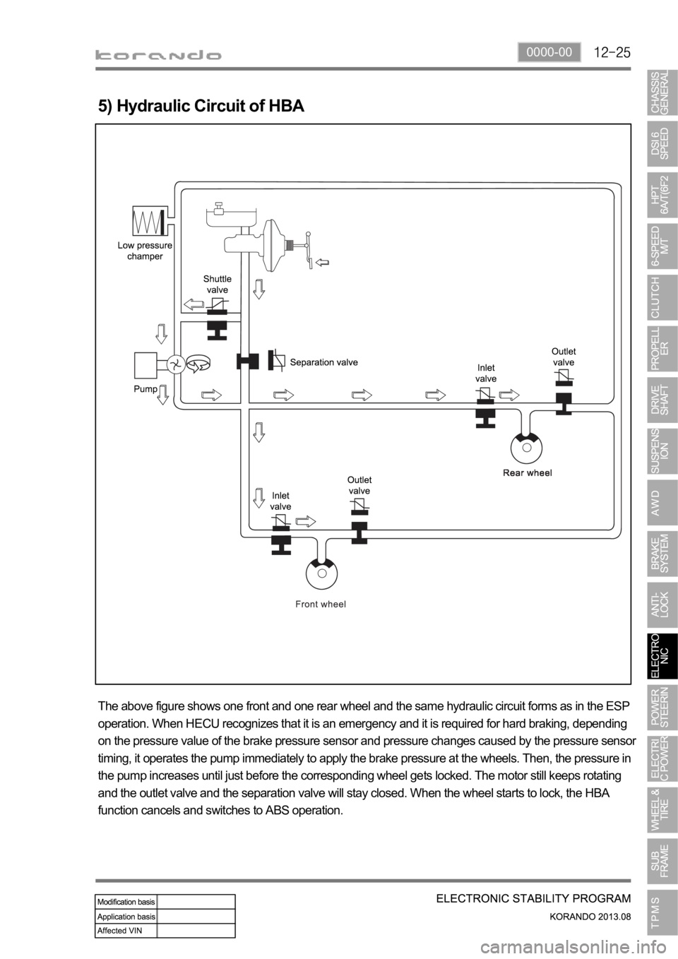
5) Hydraulic Circuit of HBA
The above figure shows one front and one rear wheel and the same hydraulic circuit forms as in the ESP
operation. When HECU recognizes that it is an emergency and it is required for hard braking, depending
on the pressure value of the brake pressure sensor and pressure changes caused by the pressure sensor
timing, it operates the pump immediately to apply the brake pressure at the wheels. Then, the pressure in
the pump increases until just before the corresponding wheel gets locked. The motor still keeps rotating
and the outlet valve and the separation valve will stay closed. When the wheel starts to lock, the HBA
function cancels and switches to ABS operation.
Page 1145 of 1336
0000-00
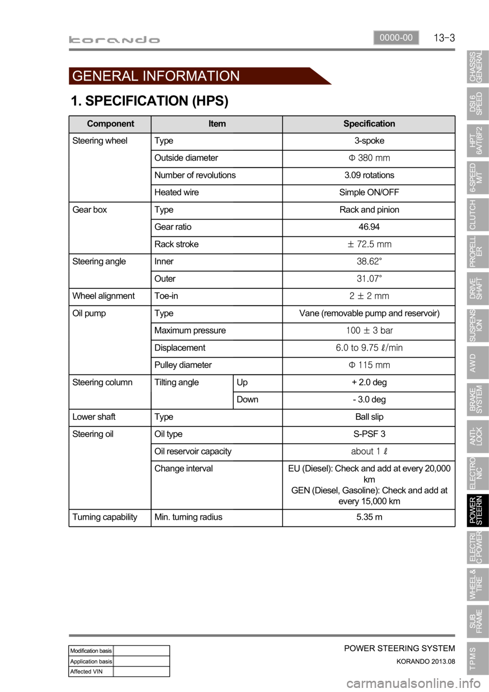
1. SPECIFICATION (HPS)
Component Item Specification
Steering wheel Type 3-spoke
Outside diameter
Number of revolutions 3.09 rotations
Heated wire Simple ON/OFF
Gear box Type Rack and pinion
Gear ratio 46.94
Rack stroke
Steering angle Inner
Outer
Wheel alignment Toe-in
Oil pump Type Vane (removable pump and reservoir)
Maximum pressure
Displacement
Pulley diameter
Steering column Tilting angle Up + 2.0 deg
Down - 3.0 deg
Lower shaft Type Ball slip
Steering oil Oil type S-PSF 3
Oil reservoir capacity
Change interval EU (Diesel): Check and add at every 20,000
km
GEN (Diesel, Gasoline): Check and add at
every 15,000 km
Turning capability Min. turning radius 5.35 m
Page 1156 of 1336
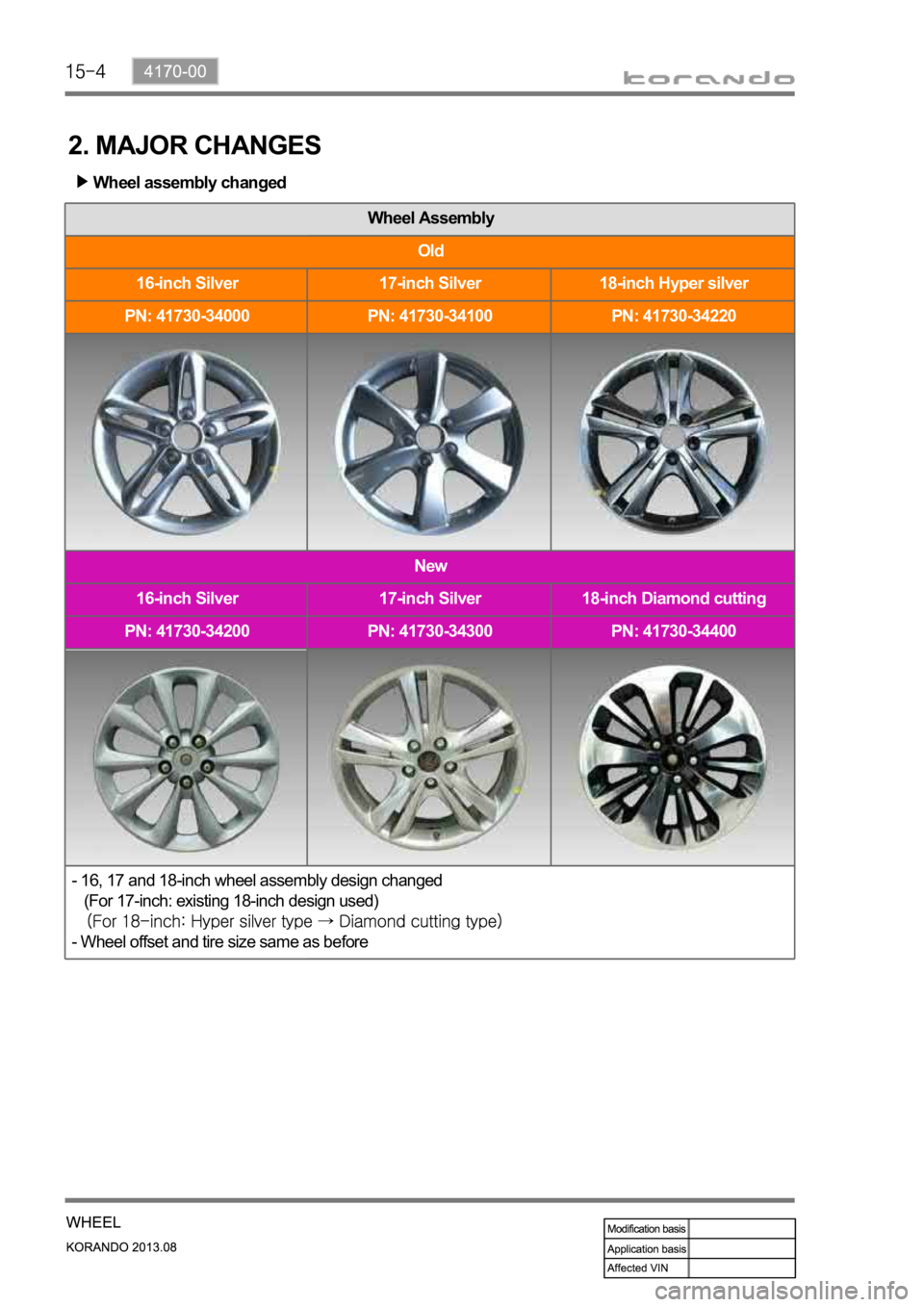
Wheel assembly changed
Wheel Assembly
Old
16-inch Silver 17-inch Silver 18-inch Hyper silver
PN: 41730-34000 PN: 41730-34100 PN: 41730-34220
New
16-inch Silver 17-inch Silver 18-inch Diamond cutting
PN: 41730-34200 PN: 41730-34300 PN: 41730-34400
- 16, 17 and 18-inch wheel assembly design changed
(For 17-inch: existing 18-inch design used)
- Wheel offset and tire size same as before
2. MAJOR CHANGES
Page 1157 of 1336

4170-00
Wheel module
The wheel modules are mounted to each wheel rim and hole. They transmit the signal of the pressure
and temperature in tire, rotating direction and wheel module ID code, etc. using the radio frequency to
the TPMS ECU.
Repair kit
Repair kit changed
Newly added TPMS (Tire Pressure Monitoring System)
Page 1171 of 1336
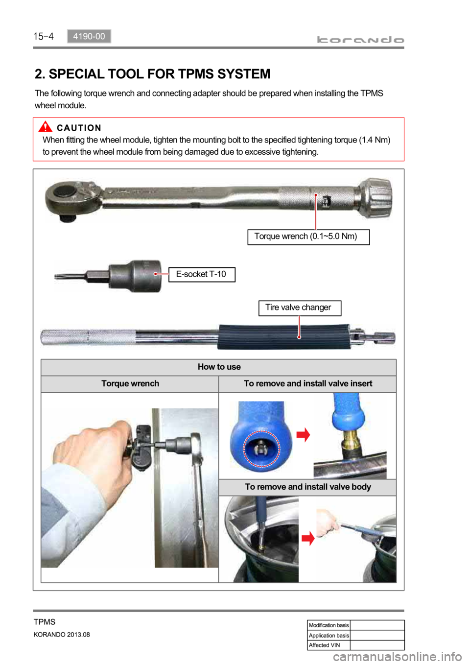
How to use
Torque wrench To remove and install valve insert
To remove and install valve body
2. SPECIAL TOOL FOR TPMS SYSTEM
The following torque wrench and connecting adapter should be prepared when installing the TPMS
wheel module.
Torque wrench (0.1~5.0 Nm)
E-socket T-10
Tire valve changer
When fitting the wheel module, tighten the mounting bolt to the specified tightening torque (1.4 Nm)
to prevent the wheel module from being damaged due to excessive tightening.
Page 1185 of 1336

7. TIRE INFLATION PROCEDURE FOR VEHICLE WITH TPMS
1) Overview
For the vehicle with TPMS, the tire should be inflated in a method different from the conventional method
since the tire pressure values displayed on the tire pressure gauge and instrument cluster are different
after inflation.
The tire pressure displayed on the instrument cluster should be checked after a certain time delay
(wireless transmission time for wheel module).
The displayed value can be changed after driving even if it was set to the specified value.
2) Tire Inflation Procedure
Park the vehicle on a flat ground and let everyone get off the vehicle. A.
This symptom is occurred as the inflation pressure displayed on the instrument cluster becomes
different by tires as different load is applied to each tire due to driving condition, number of
occupants, irregular temperature change in tire and load condition.
If there is another vehicle equipped with the TPMS, keep the distance from this vehicle for at
least 5 mm to prevent interference of wheel module transmission.
Unload cargoes if they are usually not loaded during driving.
The instrument cluster does not display every pressure change while the air is injected or
discharged to/from the tire. This is because the wheel module sends the pressure value to the
TPMS ECU every minute.
In addition, if there are other vehicles with the TPMS nearby, it might take several minutes to
display the pressure values due to radio jamming and weather condition. -
-
-
Page 1229 of 1336
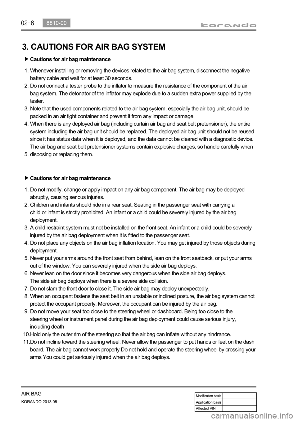
3. CAUTIONS FOR AIR BAG SYSTEM
Cautions for air bag maintenance
Whenever installing or removing the devices related to the air bag system, disconnect the negative
battery cable and wait for at least 30 seconds.
Do not connect a tester probe to the inflator to measure the resistance of the component of the air
bag system. The detonator of the inflator may explode due to a sudden extra power supplied by the
tester.
Note that the used components related to the air bag system, especially the air bag unit, should be
packed in an air tight container and prevent it from any impact or damage.
When there is any deployed air bag (including curtain air bag and seat belt pretensioner), the entire
system including the air bag unit should be replaced. The deployed air bag unit should not be reused
since it has status data when it is deployed, and the data cannot be cleared with a diagnostic device.
The air bag and seat belt pretensioner systems contain explosive charges, so handle carefully when
disposing or replacing them. 1.
2.
3.
4.
5.
Cautions for air bag maintenance
Do not modify, change or apply impact on any air bag component. The air bag may be deployed
abruptly, causing serious injuries.
Children and infants should ride in a rear seat. Seating in the passenger seat with carrying a
child or infant is strictly prohibited. An infant or a child could be severely injured by the air bag
deployment.
A child restraint system must not be installed on the front seat. An infant or a child could be severely
injured by the air bag deployment when it is fitted to the passenger seat.
Do not place any objects on the air bag inflation location. You may get injured by those objects during
deployment.
Never put your arms around the front seat from behind, lean on the front seatback, or put your arms
out of the window. You can severely injured when the side air bag deploys.
Never lean on the door since it becomes very dangerous when the side air bag deploys.
The side air bag deploys when there is a severe side collision.
Do not slam the front door to close it. The side air bag may deploy unexpectedly.
When an occupant fastens the seat belt in an unstable or inclined posture, the air bag system cannot
protect the occupant properly. Moreover, the occupant can be injured by the air bag.
Do not move your seat too close to the steering wheel or dashboard. Being too close to the
steering wheel or instrument panel during the air bag deployment could cause serious injury,
including death
Hold only the outer rim of the steering so that the air bag can inflate without any hindrance.
Do not incline toward the steering wheel. Never allow the passenger to put hands or feet on the dash
board. The air bag cannot work properly Do not hold and operate the steering wheel by crossing your
arms You could get seriously injured when the air bag deploys. 1.
2.
3.
4.
5.
6.
7.
8.
9.
10.
11.