engine coolant SSANGYONG KORANDO 2013 Workshop Manual
[x] Cancel search | Manufacturer: SSANGYONG, Model Year: 2013, Model line: KORANDO, Model: SSANGYONG KORANDO 2013Pages: 1336, PDF Size: 92.18 MB
Page 518 of 1336
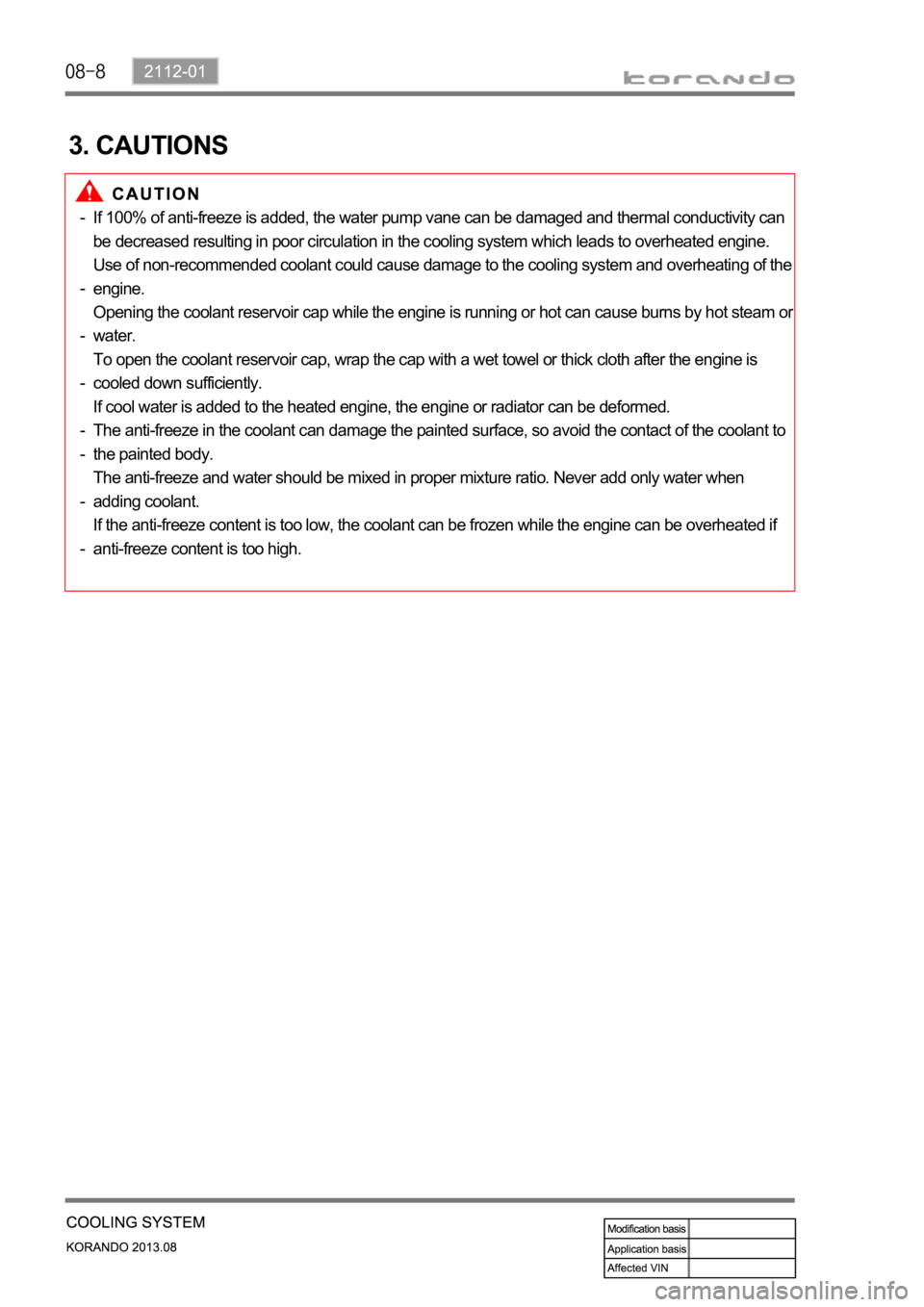
3. CAUTIONS
If 100% of anti-freeze is added, the water pump vane can be damaged and thermal conductivity can
be decreased resulting in poor circulation in the cooling system which leads to overheated engine.
Use of non-recommended coolant could cause damage to the cooling system and overheating of the
engine.
Opening the coolant reservoir cap while the engine is running or hot can cause burns by hot steam o
r
water.
To open the coolant reservoir cap, wrap the cap with a wet towel or thick cloth after the engine is
cooled down sufficiently.
If cool water is added to the heated engine, the engine or radiator can be deformed.
The anti-freeze in the coolant can damage the painted surface, so avoid the contact of the coolant to
the painted body.
The anti-freeze and water should be mixed in proper mixture ratio. Never add only water when
adding coolant.
If the anti-freeze content is too low, the coolant can be frozen while the engine can be overheated if
anti-freeze content is too high. -
-
-
-
-
-
-
-
Page 522 of 1336

Water pump
The water pump is driven by the engine drive belt and supplies
the coolant to each area of the engine.
Coolant reservoir
Thermostat
When the engine coolant
starts to open (fully open at
flow to the radiator to maintain
the engine temperature.
1. OVERVIEW
The coolant system is to keep the engine temperature stable.
2. COMPONENTS
Page 523 of 1336

2112-01
Coolant temperature
sensor
Measures the coolant
temperature and sends the result
to the engine ECU.
Radiator
Radiates the heat through fins and cools
down the hot coolant as the coolant
passes through the tube of the radiator
core.PWM fan
Circulates the fresh air forcibly to exchange
heat with the radiator core fin.
Coolant outlet port
Page 557 of 1336
1490-00
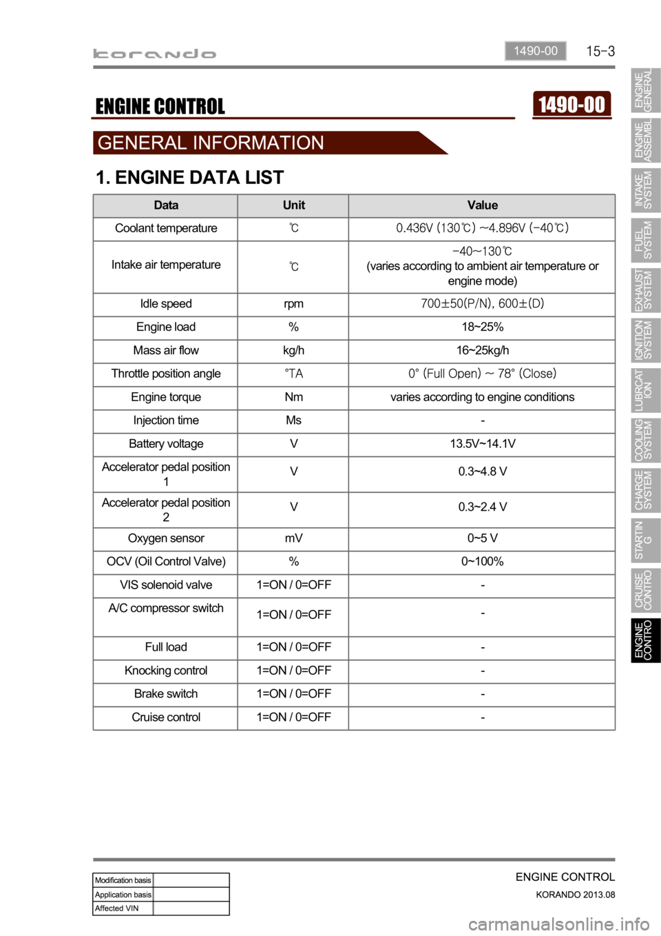
1. ENGINE DATA LIST
Data Unit Value
Coolant temperature
Intake air temperature(varies according to ambient air temperature or
engine mode)
Idle speed rpm
Engine load % 18~25%
Mass air flow kg/h 16~25kg/h
Throttle position angle
Engine torque Nm varies according to engine conditions
Injection time Ms -
Battery voltage V 13.5V~14.1V
Accelerator pedal position
1V 0.3~4.8 V
Accelerator pedal position
2V 0.3~2.4 V
Oxygen sensor mV 0~5 V
OCV (Oil Control Valve) % 0~100%
VIS solenoid valve 1=ON / 0=OFF -
A/C compressor switch
1=ON / 0=OFF-
Full load 1=ON / 0=OFF -
Knocking control 1=ON / 0=OFF -
Brake switch 1=ON / 0=OFF -
Cruise control 1=ON / 0=OFF -
Page 559 of 1336

0000-00
Purge control
solenoid valve
G20DF engine
ECUCoolant Temp
sensorCamshaft position
sensor
Crankshaft position
sensor
T-MAP sensorVIS solenoid valveElectronic throttle
bodyMagnetic trigger
ring
Front oxygen
sensor
Page 561 of 1336
0000-00
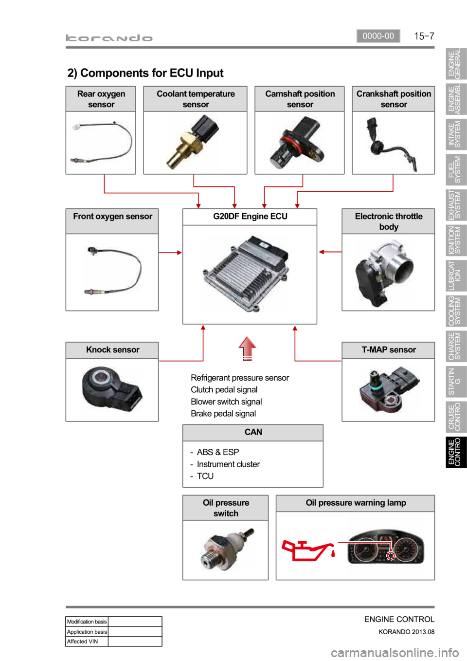
Rear oxygen
sensor
2) Components for ECU Input
Coolant temperature
sensorCamshaft position
sensorCrankshaft position
sensor
Front oxygen sensor
Knock sensor
G20DF Engine ECUElectronic throttle
body
Refrigerant pressure sensor
Clutch pedal signal
Blower switch signal
Brake pedal signal
CAN
ABS & ESP
Instrument cluster
TCU -
-
-
Oil pressure
switchOil pressure warning lamp
T-MAP sensor
Page 564 of 1336
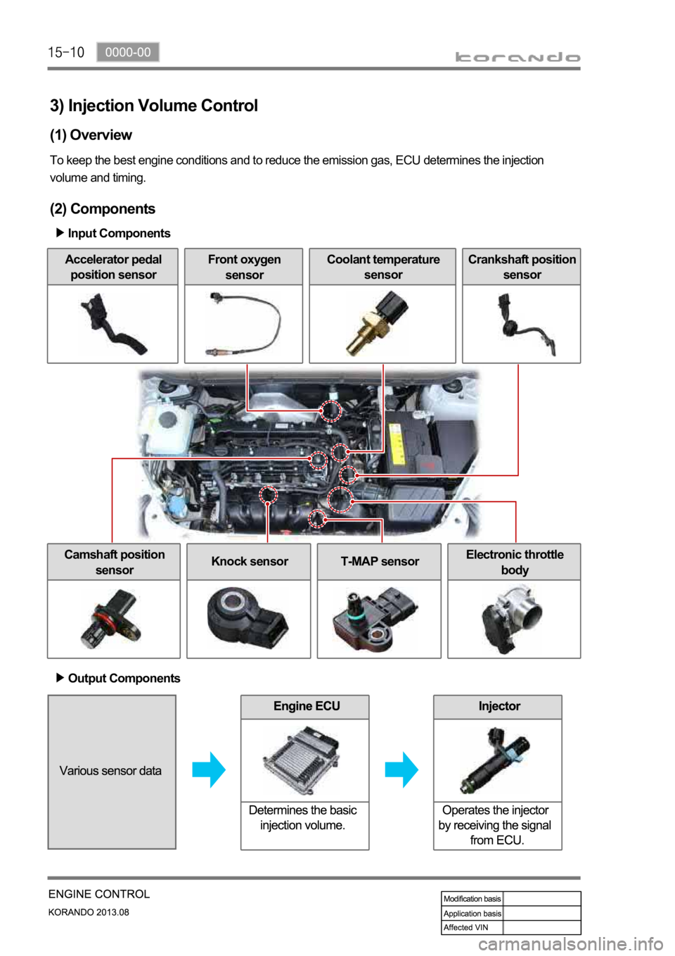
3) Injection Volume Control
(1) Overview
To keep the best engine conditions and to reduce the emission gas, ECU determines the injection
volume and timing.
(2) Components
Input Components
Accelerator pedal
position sensorFront oxygen
sensorCoolant temperature
sensorCrankshaft position
sensor
Camshaft position
sensorKnock sensorT-MAP sensorElectronic throttle
body
Output Components
Page 567 of 1336
0000-00
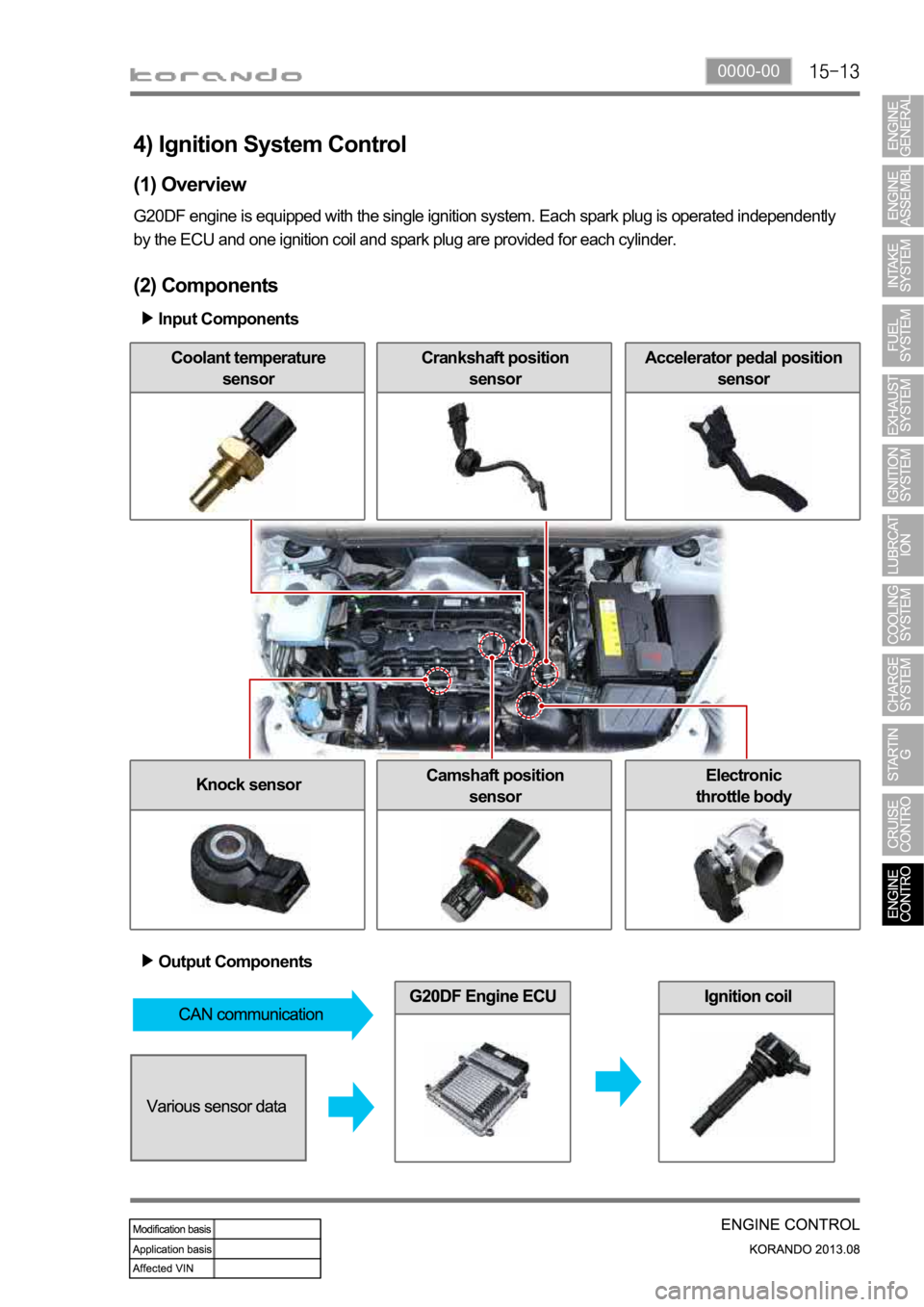
Coolant temperature
sensor
4) Ignition System Control
(1) Overview
G20DF engine is equipped with the single ignition system. Each spark plug is operated independently
by the ECU and one ignition coil and spark plug are provided for each cylinder.
(2) Components
Input Components
Crankshaft position
sensorAccelerator pedal position
sensor
Knock sensorCamshaft position
sensorElectronic
throttle body
Output Components
Page 569 of 1336
0000-00
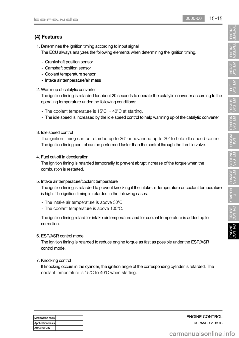
(4) Features
Determines the ignition timing according to input signal
The ECU always analyzes the following elements when determining the ignition timing. 1.
Crankshaft position sensor
Camshaft position sensor
Coolant temperature sensor
Intake air temperature/air mass -
-
-
-
Warm-up of catalytic converter
The ignition timing is retarded for about 20 seconds to operate the catalytic converter according to the
operating temperature under the following conditions: 2.
The idle speed is increased by the idle speed control to help warming up of the catalytic converter -
-
Idle speed control
The ignition timing control can be performed faster than the control through the throttle valve.
Fuel cut-off in deceleration
The ignition timing is retarded temporarily to prevent abrupt increase of the torque when the
combustion is restarted.
Intake air temperature/coolant temperature
The ignition timing is retarded to prevent knocking if the intake air temperature or coolant temperature
is high. The ignition timing is retarded in the following cases. 3.
4.
5.
-
-
The ignition timing retard for intake air temperature and for coolant temperature is added up for
correction.
ESP/ASR control mode
The ignition timing is retarded to reduce engine torque as fast as possible under the ESP/ASR
control mode.
Knocking control
If knocking occurs in the cylinder, the ignition angle of the corresponding cylinder is retarded. The
6.
7.
Page 571 of 1336
0000-00
(2) Warm-up Control Function
Low voltage
If low voltage is detected by the ECU, the idle speed increases up to 100 rpm selectively under the
driving mode until the ignition switch is turned off. Idle speed control
The idle speed is controlled according to the fuel/air mixture when the engine load is changed, the
power steering wheel is turned to its end, the selector lever is in the "D" position and the A/C compresso
r
is in operation. It is also controlled according to the charge level during the purge control operation.
Ignition timing
The idle speed is controlled according to the fuel/air mixture when the engine load is changed, The
Air conditioner compressor operation
The air conditioner control unit sends the air conditioner operation signal to the ECU to increase the
throttle valve opening amount in order to prevent reduction of the engine speed when the air conditioner
compressor is in operation at idling.
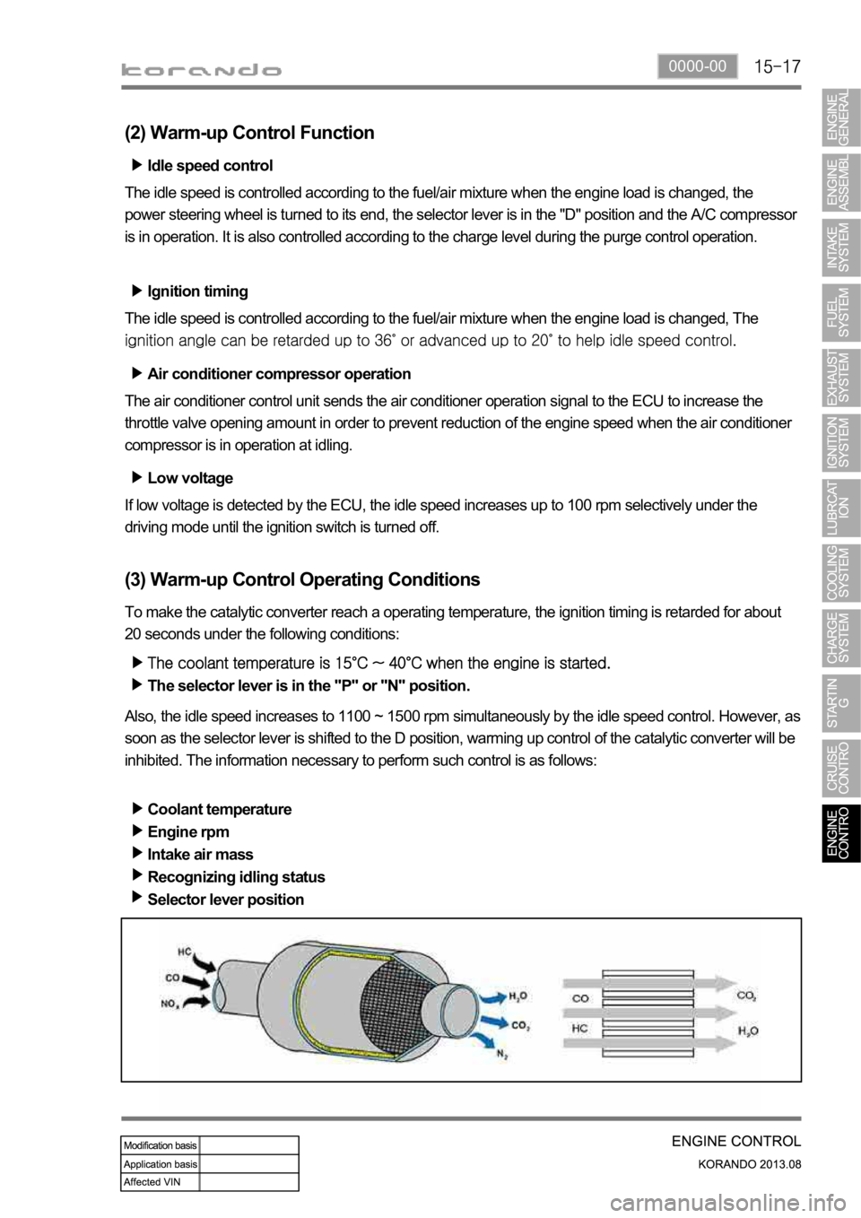
(3) Warm-up Control Operating Conditions
To make the catalytic converter reach a operating temperature, the ignition timing is retarded for about
20 seconds under the following conditions:
The selector lever is in the "P" or "N" position.
Also, the idle speed increases to 1100 ~ 1500 rpm simultaneously by the idle speed control. However, as
soon as the selector lever is shifted to the D position, warming up control of the catalytic converter will be
inhibited. The information necessary to perform such control is as follows:
Coolant temperature
Engine rpm
Intake air mass
Recognizing idling status
Selector lever position