SSANGYONG KORANDO 2013 Service Manual
KORANDO 2013
SSANGYONG
SSANGYONG
https://www.carmanualsonline.info/img/67/57503/w960_57503-0.png
SSANGYONG KORANDO 2013 Service Manual
Trending: load capacity, radiator cap, TPMS reset, parking sensors, 4WD, key battery, recommended oil
Page 621 of 1336
0000-00
Luggage lamp switch
Overhead console
switchFront seat heating and ventilation switch
With heating and ventilation
switchWith heating switch
Driver power seat
switch
Center room lamp
switch
Rear door switch (RH)Rear door switch (LH)
Tailgate switch
Page 622 of 1336
4. SCHEMATIC DIAGRAM FOR WIRING AND ELECTRICAL
DEVICES
1) Wiring Harness Arrangement
Page 623 of 1336
0000-00
2) Electrical Devices Mounting Locations
Page 624 of 1336
3) Connector, Ground And Splice Pack
Connector
Page 625 of 1336
0000-00
Ground
Splice pack
Page 626 of 1336
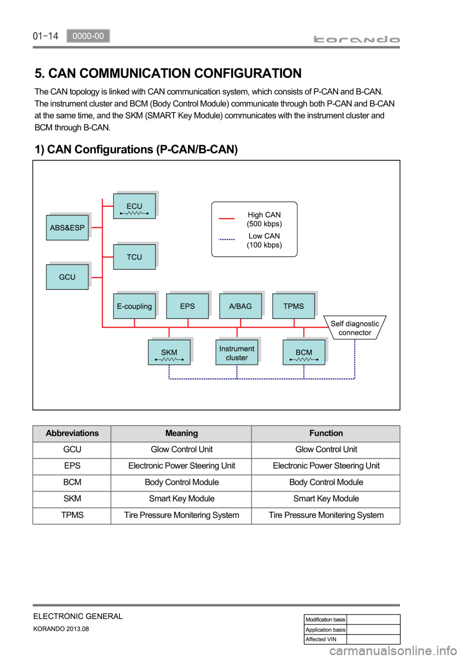
5. CAN COMMUNICATION CONFIGURATION
The CAN topology is linked with CAN communication system, which consists of P-CAN and B-CAN.
The instrument cluster and BCM (Body Control Module) communicate through both P-CAN and B-CAN
at the same time, and the SKM (SMART Key Module) communicates with the instrument cluster and
BCM through B-CAN.
1) CAN Configurations (P-CAN/B-CAN)
Abbreviations Meaning Function
GCU Glow Control Unit Glow Control Unit
EPS Electronic Power Steering Unit Electronic Power Steering Unit
BCM Body Control Module Body Control Module
SKM Smart Key Module Smart Key Module
TPMS Tire Pressure Monitering System Tire Pressure Monitering System
Page 627 of 1336
0000-00
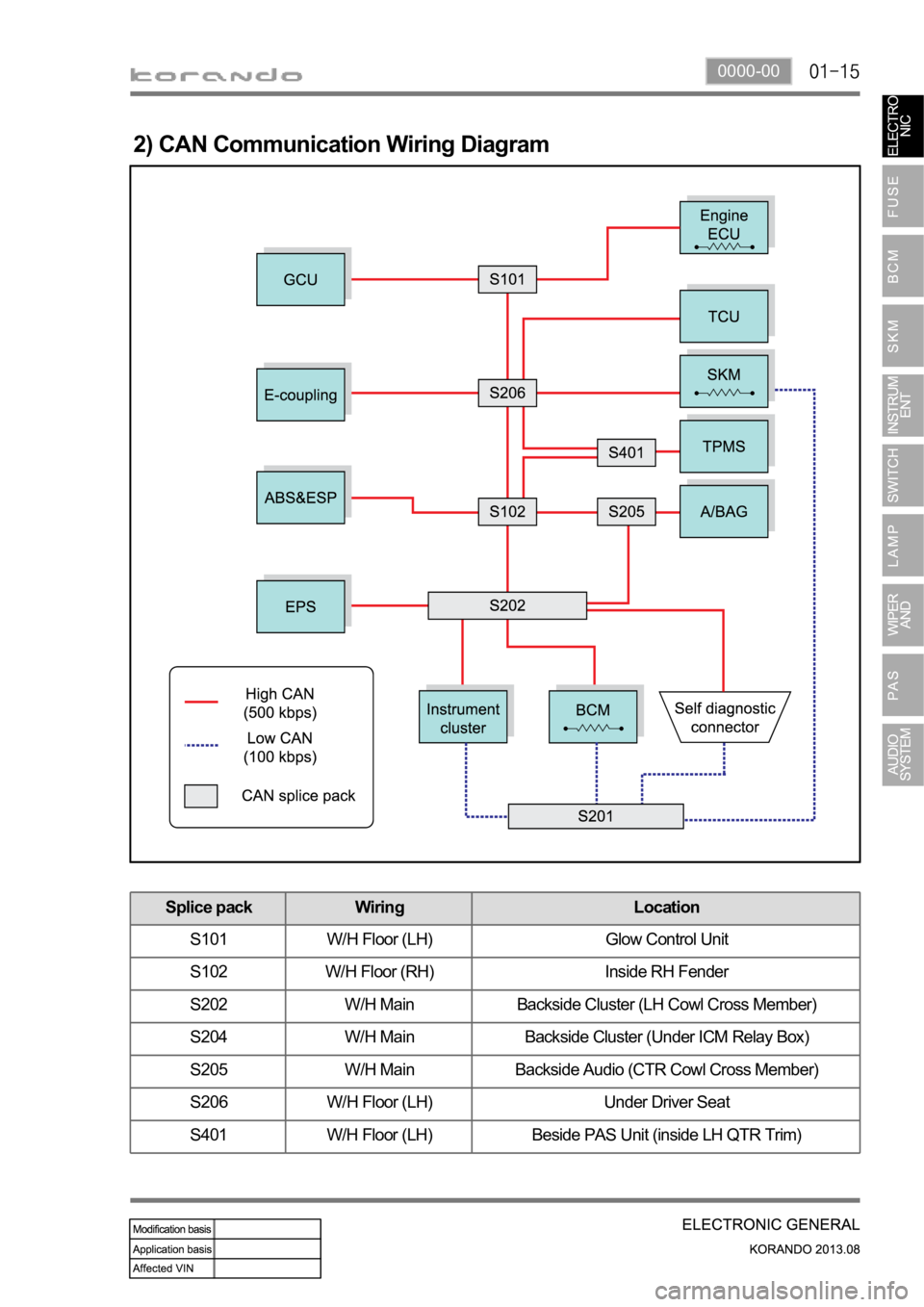
2) CAN Communication Wiring Diagram
Splice pack Wiring Location
S101 W/H Floor (LH) Glow Control Unit
S102 W/H Floor (RH) Inside RH Fender
S202 W/H Main Backside Cluster (LH Cowl Cross Member)
S204 W/H Main Backside Cluster (Under ICM Relay Box)
S205 W/H Main Backside Audio (CTR Cowl Cross Member)
S206 W/H Floor (LH) Under Driver Seat
S401 W/H Floor (LH) Beside PAS Unit (inside LH QTR Trim)
Page 628 of 1336
Page 629 of 1336
8410-00
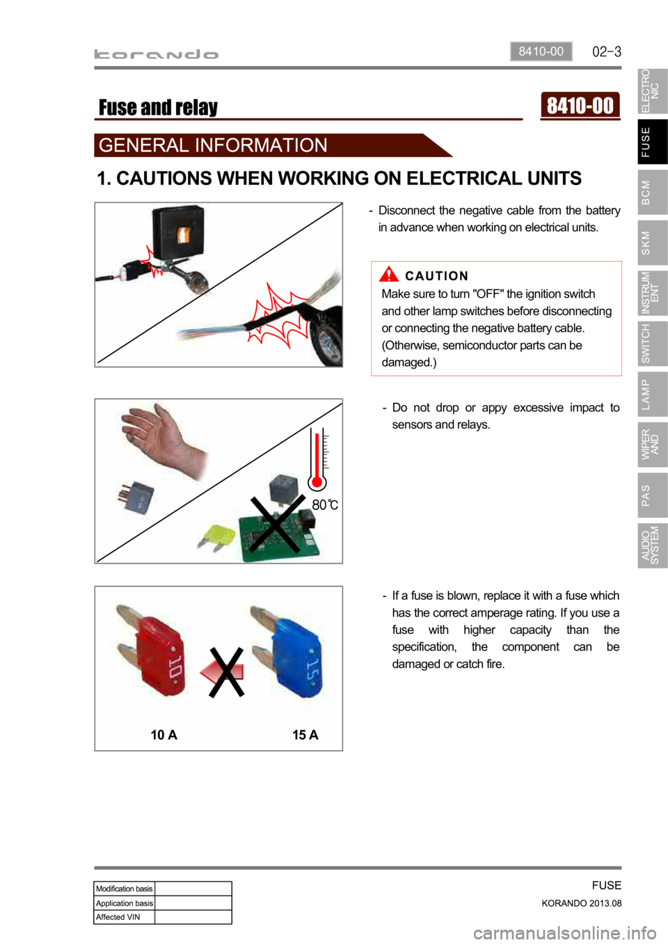
1. CAUTIONS WHEN WORKING ON ELECTRICAL UNITS
Disconnect the negative cable from the battery
in advance when working on electrical units. -
If a fuse is blown, replace it with a fuse which
has the correct amperage rating. If you use a
fuse with higher capacity than the
specification, the component can be
damaged or catch fire. -Do not drop or appy excessive impact to
sensors and relays. -
10 A 15 A
Make sure to turn "OFF" the ignition switch
and other lamp switches before disconnecting
or connecting the negative battery cable.
(Otherwise, semiconductor parts can be
damaged.)
Page 630 of 1336
Make sure a connector is connected
securely. Loose connection results in
malfunction. -
When disconnecting a connector equipped with
a lock, press it down to the direction in the below
figure. -
When checking voltage or continuity of the
connector terminal with a circuit tester, connect
the tester probe to the terminal at the harness
side. For a sealed type connector, connect the
probe to the terminal through the hole in the
rubber cap of the wiring. Take care not to
damage the insulation of the wires. Insert the
probe until it contacts the terminal completely. -
When inspecting the airbag system, make sure to use a diagnostic device, not a circuit tester.
Trending: bulb, reset sun roof, brake sensor, oil dipstick, clutch control, water pump, coolant level


