SSANGYONG KORANDO 2013 Service Manual
KORANDO 2013
SSANGYONG
SSANGYONG
https://www.carmanualsonline.info/img/67/57503/w960_57503-0.png
SSANGYONG KORANDO 2013 Service Manual
Page 185 of 1336
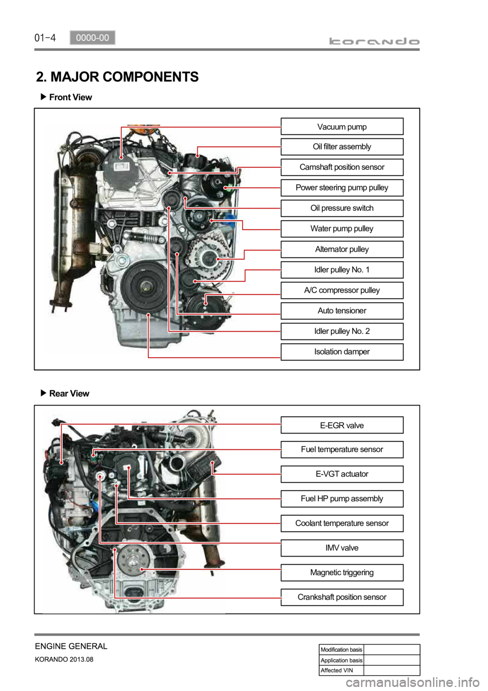
2. MAJOR COMPONENTS
Front View
Rear View
E-EGR valve
Fuel temperature sensor
Fuel HP pump assemblyE-VGT actuator
Coolant temperature sensor
IMV valve
Magnetic triggering
Crankshaft position sensor
Vacuum pump
Oil filter assembly
Camshaft position sensor
Power steering pump pulley
Water pump pulley
Alternator pulley
Idler pulley No. 1
A/C compressor pulley
Auto tensioner
Idler pulley No. 2
Isolation damper
Oil pressure switch
Page 200 of 1336
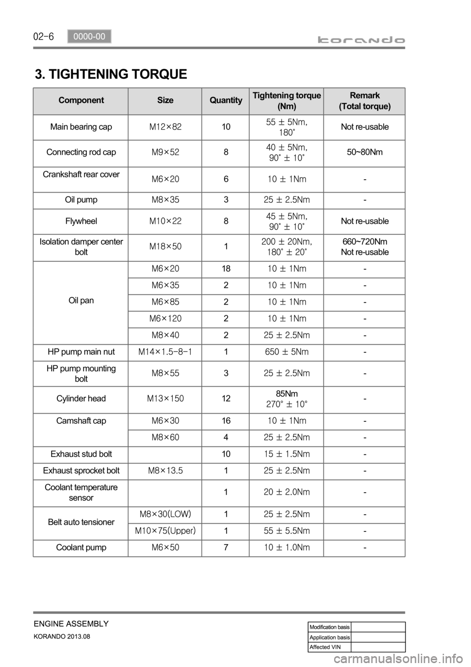
3. TIGHTENING TORQUE
Component Size QuantityTightening torque
(Nm)Remark
(Total torque)
Main bearing cap
10Not re-usable
Connecting rod cap
850~80Nm
Crankshaft rear cover
6-
Oil pump
3-
Flywheel
8Not re-usable
Isolation damper center
bolt
1660~720Nm
Not re-usable
Oil pan
18-
2-
2-
2-
2-
HP pump main nut
1-
HP pump mounting
bolt
3-
Cylinder head
1285Nm-
Camshaft cap
16-
4-
Exhaust stud bolt 10
-
Exhaust sprocket bolt
1-
Coolant temperature
sensor1-
Belt auto tensioner
1-
1-
Coolant pump
7-
Page 208 of 1336
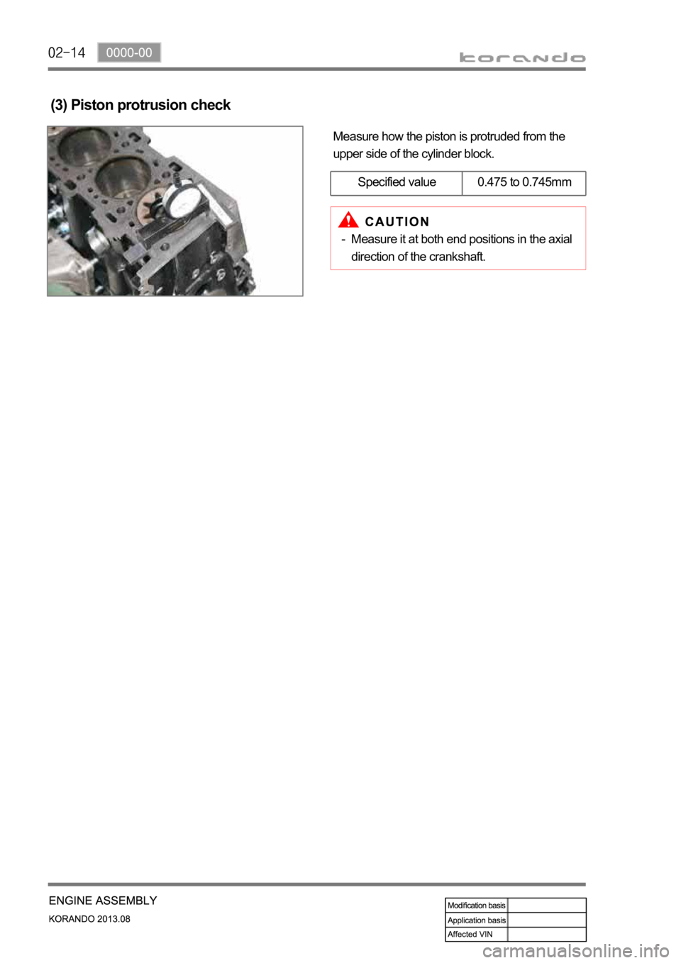
Measure how the piston is protruded from the
upper side of the cylinder block.
(3) Piston protrusion check
Specified value 0.475 to 0.745mm
Measure it at both end positions in the axial
direction of the crankshaft. -
Page 212 of 1336
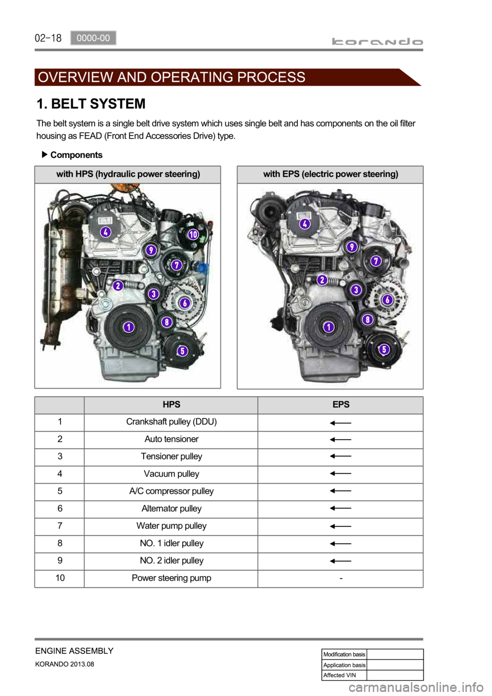
with EPS (electric power steering)with HPS (hydraulic power steering)
1. BELT SYSTEM
The belt system is a single belt drive system which uses single belt and has components on the oil filter
housing as FEAD (Front End Accessories Drive) type.
Components
HPS EPS
1 Crankshaft pulley (DDU)
2 Auto tensioner
3 Tensioner pulley
4 Vacuum pulley
5 A/C compressor pulley
6 Alternator pulley
7 Water pump pulley
8 NO. 1 idler pulley
9 NO. 2 idler pulley
10 Power steering pump -
Page 219 of 1336
0000-00
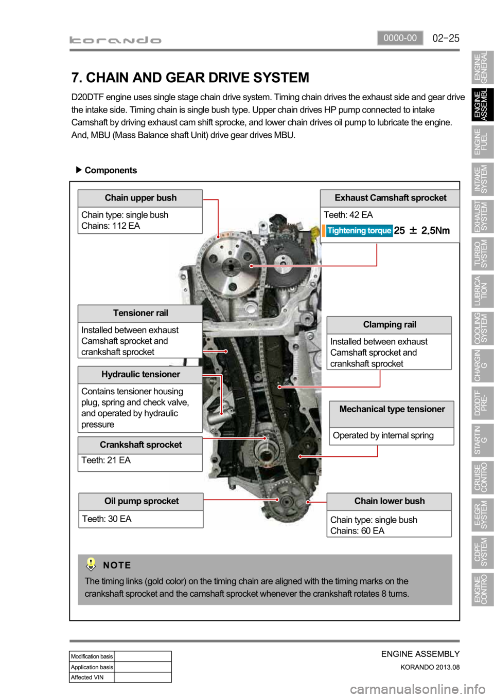
Chain upper bush
Chain type: single bush
Chains: 112 EA
Hydraulic tensioner
Contains tensioner housing
plug, spring and check valve,
and operated by hydraulic
pressure
Exhaust Camshaft sprocket
Teeth: 42 EA
Clamping rail
Installed between exhaust
Camshaft sprocket and
crankshaft sprocket
7. CHAIN AND GEAR DRIVE SYSTEM
D20DTF engine uses single stage chain drive system. Timing chain drives the exhaust side and gear drive
the intake side. Timing chain is single bush type. Upper chain drives HP pump connected to intake
Camshaft by driving exhaust cam shift sprocke, and lower chain drives oil pump to lubricate the engine.
And, MBU (Mass Balance shaft Unit) drive gear drives MBU.
Components
Chain lower bush
Chain type: single bush
Chains: 60 EA
Mechanical type tensioner
Operated by internal spring
The timing links (gold color) on the timing chain are aligned with the timing marks on the
crankshaft sprocket and the camshaft sprocket whenever the crankshaft rotates 8 turns.
Oil pump sprocket
Teeth: 30 EA
Tensioner rail
Installed between exhaust
Camshaft sprocket and
crankshaft sprocket
Crankshaft sprocket
Teeth: 21 EA
Page 222 of 1336
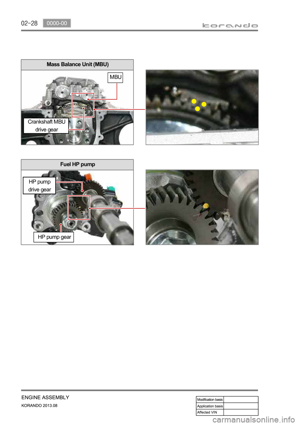
Mass Balance Unit (MBU)
Fuel HP pump
HP pump gear
Crankshaft MBU
drive gear
MBU
HP pump
drive gear
Page 226 of 1336
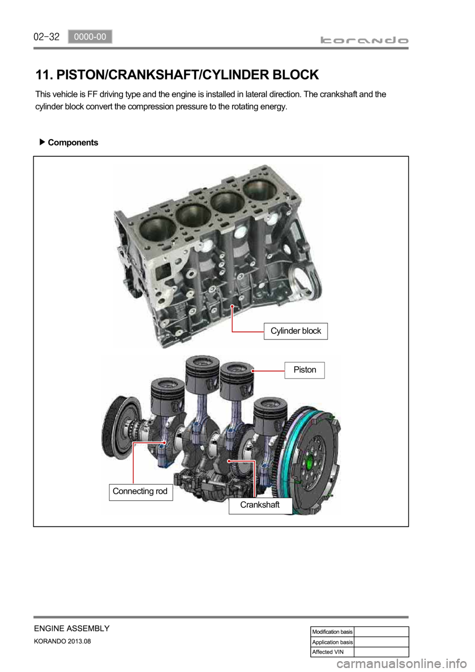
11. PISTON/CRANKSHAFT/CYLINDER BLOCK
This vehicle is FF driving type and the engine is installed in lateral direction. The crankshaft and the
cylinder block convert the compression pressure to the rotating energy.
Components
Cylinder block
Piston
Connecting rod
Crankshaft
Page 251 of 1336
0000-00
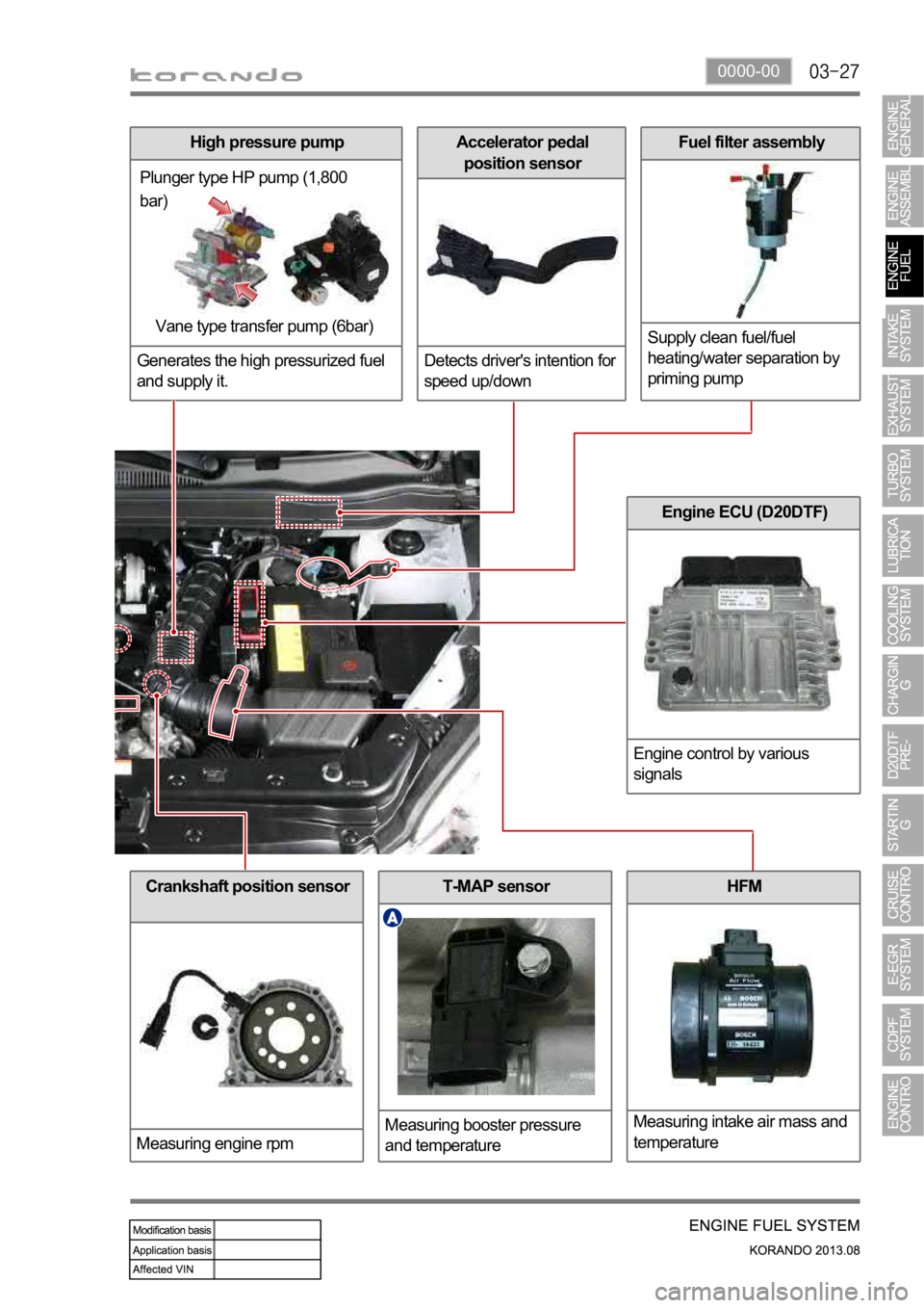
Crankshaft position sensor
Measuring engine rpmT-MAP sensor
Measuring booster pressure
and temperatureHFM
Measuring intake air mass and
temperature
Engine ECU (D20DTF)
Engine control by various
signals
High pressure pump
Generates the high pressurized fuel
and supply it.
Plunger type HP pump (1,800
bar)
Vane type transfer pump (6bar)
Accelerator pedal
position sensor
Detects driver's intention for
speed up/downFuel filter assembly
Supply clean fuel/fuel
heating/water separation by
priming pump
Page 254 of 1336
The engine ECU calculates the accelerator pedal based on the input signals from various sensors, and
controls the overall operation of the vehicle.
The ECU receives the signals from various sensor through data line, and performs effective air-fuel ratio
control based on these signals.
The crankshaft speed (position) sensor measures the engine speed, and the camshaft speed (position)
sensor determines the order of injections, and the ECU detects the amount of the accelerator pedal
depressed (driver's will) by receiving the electrical signals from the accelerator pedal sensor.
The mass air flow sensor detects the volume of intake air and sends the value to the ECU.
The major function of the ECU is controlling air-fuel ratio to reduce the emission level (EGR valve control)
by detecting instantaneous air flow change with the signals from the mass air flow sensor.
Also, the ECU uses the signals from the coolant temperature & air temperature sensors, booster pressure
sensor, atmospheric pressure sensor to: a) determine injection starting point and set value for pilot
injection, and b) deal with various operations and variable conditions.
Page 307 of 1336
0000-00
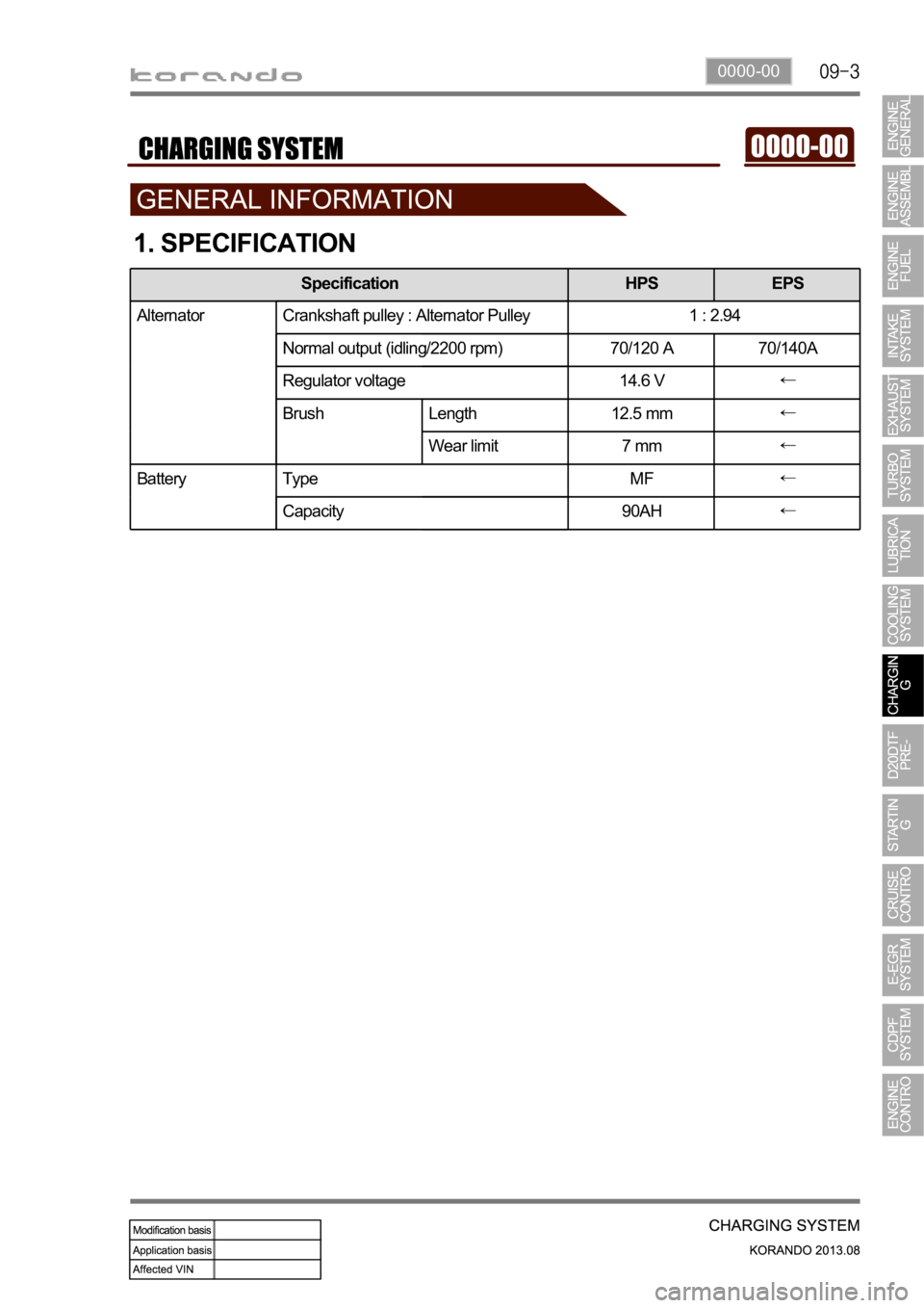
1. SPECIFICATION
Specification HPS EPS
Alternator Crankshaft pulley : Alternator Pulley 1 : 2.94
Normal output (idling/2200 rpm) 70/120 A 70/140A
Regulator voltage 14.6 V
Brush Length 12.5 mm
Wear limit 7 mm
Battery Type MF
Capacity 90AH
