fuel pressure SSANGYONG KORANDO 2013 Service Manual
[x] Cancel search | Manufacturer: SSANGYONG, Model Year: 2013, Model line: KORANDO, Model: SSANGYONG KORANDO 2013Pages: 1336, PDF Size: 92.18 MB
Page 185 of 1336
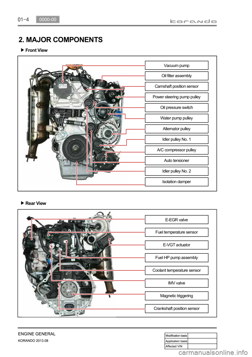
2. MAJOR COMPONENTS
Front View
Rear View
E-EGR valve
Fuel temperature sensor
Fuel HP pump assemblyE-VGT actuator
Coolant temperature sensor
IMV valve
Magnetic triggering
Crankshaft position sensor
Vacuum pump
Oil filter assembly
Camshaft position sensor
Power steering pump pulley
Water pump pulley
Alternator pulley
Idler pulley No. 1
A/C compressor pulley
Auto tensioner
Idler pulley No. 2
Isolation damper
Oil pressure switch
Page 190 of 1336
0000-00
5) Guidelines on Engine Service
(1) Cautions before service works
Make sure to disconnect the negative (-) cable from the battery to prevent any damage to electric
systems.
Make sure to clean the working area and to prepare the necessary tools before service works.
Always place the ignition switch to OFF position if not required. Otherwise, there could be
unexpected damage to electric devices or personal injuries due to short-circuit.
To prevent the foreign material from entering into the fuel injection system, completely seal the inlets
of HP pump, fuel hoses and high pressure pipes.
To remoev the engine, use the dedicated equipments such as engine jack, transmission jack, engine
stand and engine crane. -
-
-
-
-
(2) Engine and accessories
When disassembling the engine, related parts (bolts, gaskets, etc.) should be stored as a set.
Clean the components completely with engine oil before assembling if needed.
Fully drain the engine oil, coolant and fuel from the vehicle and seal the inlets with the plugs before
removing the engine.
All the interference should be eliminated before removing the engine. -
-
-
-
(3) Electric devices
To prevent any damage to electric systems, make sure to disconnect the negative (-) cable from the
battery and place the ignition switch to OFF position before servicing.
Use only the specified parts with same ratings when replacing the electric devices. Check the
grounds and connections for looseness. -
- To prevent the personal injuries and vehicle damages that can be caused by mistakes during service
and to provide the optimized performance and safety after service works, the service technicials must
keep the basic cautions and service guidelines below. These could be easily forgotten during service
works.
Engine has a lot of precise components. The specified tightening torque and correct procedures should
be kept during service works. And, the working area is always clean and well prepared.
Extraordinary care should be taken when servicing the electric systems. Currently, the engine uses a lot
of electric devices. Short circuit and poor contact may cause the low engine performance, incomplete
combustion and other abnormalities.
Page 202 of 1336
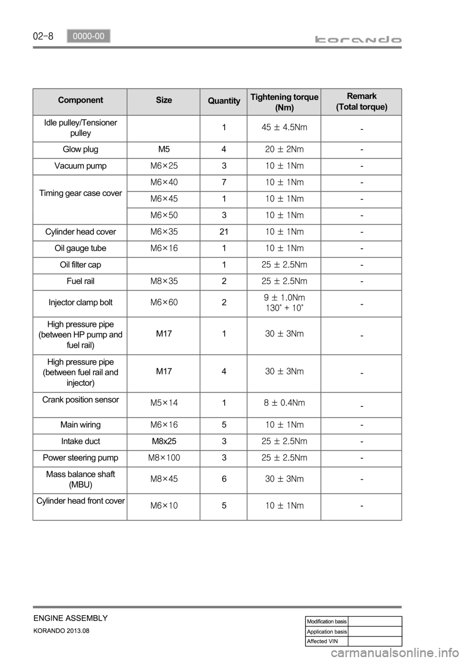
Oil gauge tube1-
Oil filter cap 1
-
Fuel rail
2-
Injector clamp bolt
2-
High pressure pipe
(between HP pump and
fuel rail)M17 1
-
High pressure pipe
(between fuel rail and
injector)M17 4
-
Crank position sensor
1-
Main wiring
5-
Intake duct M8x25 3
-
Power steering pump
3-
Mass balance shaft
(MBU)
6-
Cylinder head front cove
r5-
Timing gear case cover
7-
1-
3-
Cylinder head cover
21-
Component Size
QuantityTightening torque
(Nm)Remark
(Total torque)
Idle pulley/Tensioner
pulley1
-
Glow plug M5 4
-
Vacuum pump
3-
Page 227 of 1336
0000-00
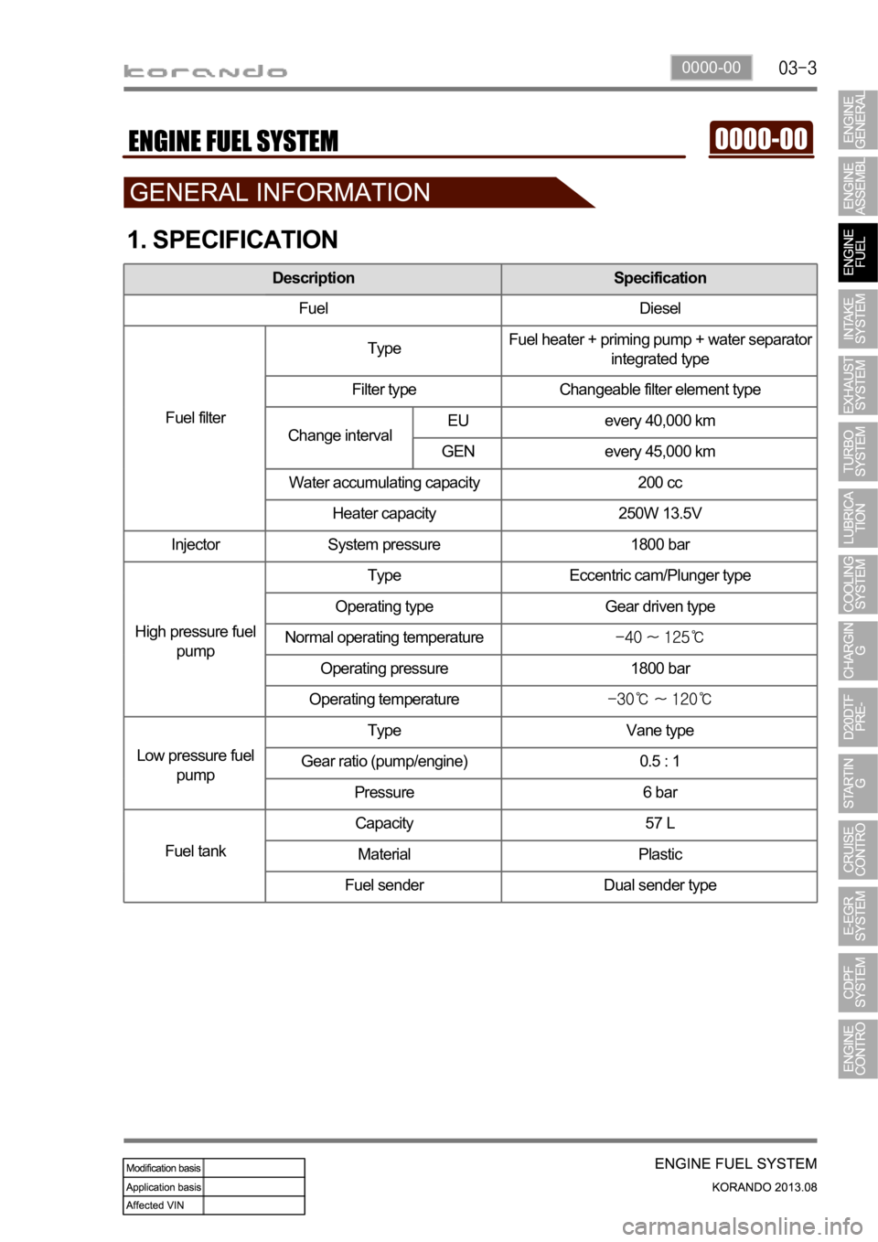
1. SPECIFICATION
Description Specification
Fuel Diesel
Fuel filterTypeFuel heater + priming pump + water separator
integrated type
Filter type Changeable filter element type
every 40,000 km
every 45,000 km
Water accumulating capacity 200 cc
Heater capacity 250W 13.5V
Injector System pressure 1800 bar
High pressure fuel
pumpType Eccentric cam/Plunger type
Operating type Gear driven type
Normal operating temperature
Operating pressure 1800 bar
Operating temperature
Low pressure fuel
pumpType Vane type
Gear ratio (pump/engine) 0.5 : 1
Pressure 6 bar
Fuel tankCapacity 57 L
Material Plastic
Fuel sender Dual sender type
Change intervalEU
GEN
Page 229 of 1336
0000-00
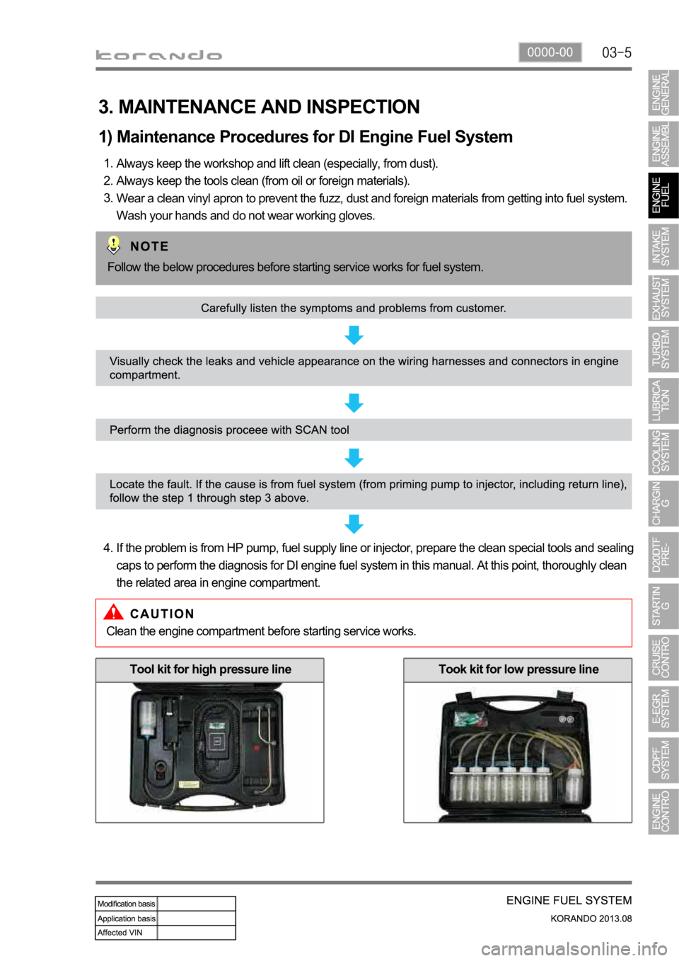
3. MAINTENANCE AND INSPECTION
1) Maintenance Procedures for DI Engine Fuel System
Always keep the workshop and lift clean (especially, from dust).
Always keep the tools clean (from oil or foreign materials).
Wear a clean vinyl apron to prevent the fuzz, dust and foreign materials from getting into fuel system.
Wash your hands and do not wear working gloves. 1.
2.
3.
Follow the below procedures before starting service works for fuel system.
If the problem is from HP pump, fuel supply line or injector, prepare the clean special tools and sealing
caps to perform the diagnosis for DI engine fuel system in this manual. At this point, thoroughly clean
the related area in engine compartment. 4.
Clean the engine compartment before starting service works.
Tool kit for high pressure lineTook kit for low pressure line
Page 232 of 1336
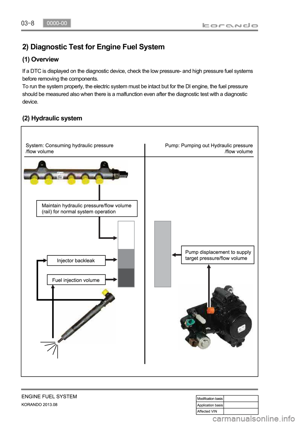
2) Diagnostic Test for Engine Fuel System
(1) Overview
If a DTC is displayed on the diagnostic device, check the low pressure- and high pressure fuel systems
before removing the components.
To run the system properly, the electric system must be intact but for the DI engine, the fuel pressure
should be measured also when there is a malfunction even after the diagnostic test with a diagnostic
device.
(2) Hydraulic system
Page 234 of 1336
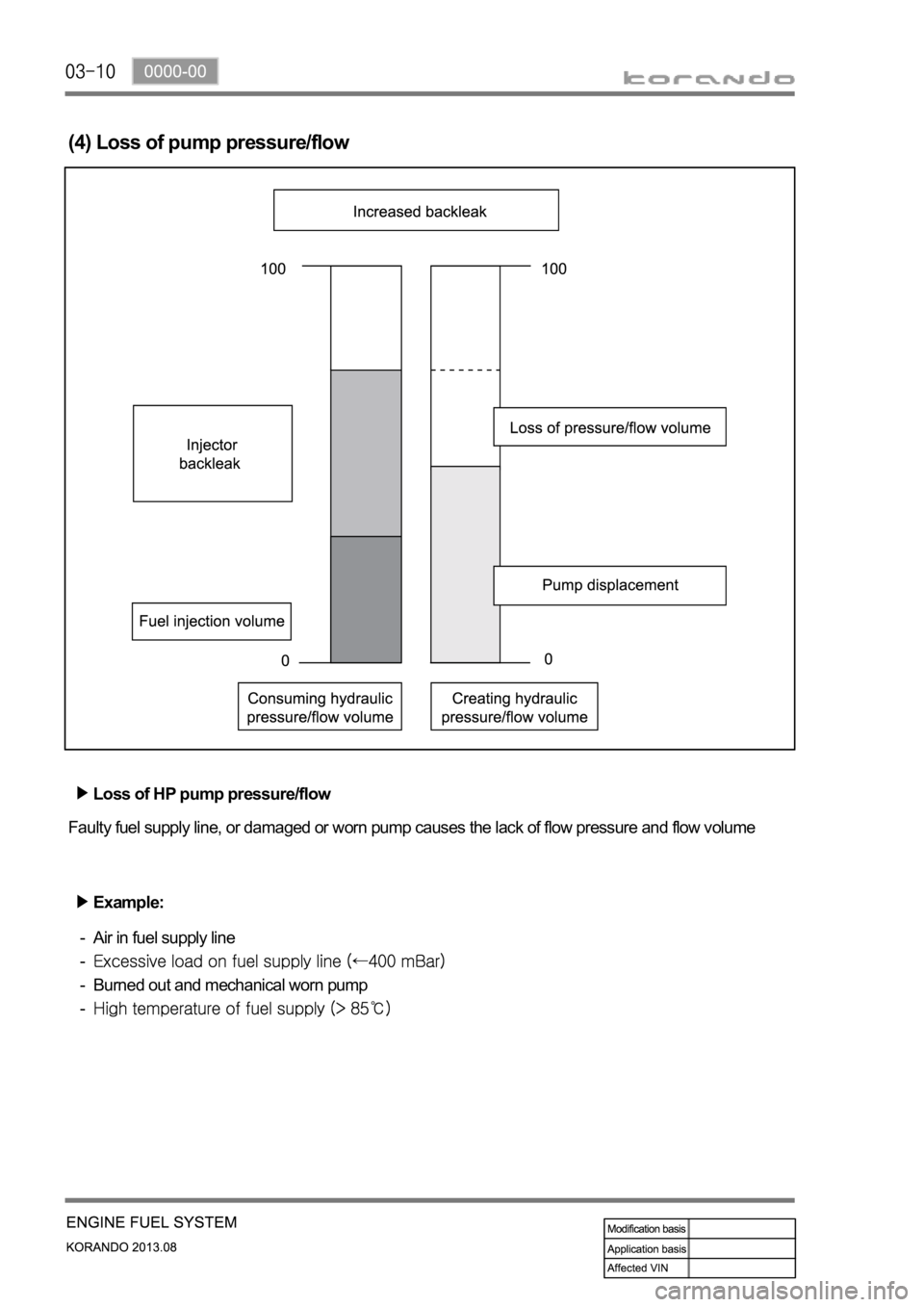
(4) Loss of pump pressure/flow
Loss of HP pump pressure/flow
Faulty fuel supply line, or damaged or worn pump causes the lack of flow pressure and flow volume
Example:
Air in fuel supply line
Burned out and mechanical worn pump
-
-
-
-
Page 235 of 1336
0000-00
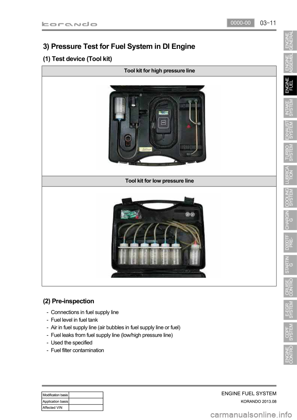
3) Pressure Test for Fuel System in DI Engine
(1) Test device (Tool kit)
Tool kit for high pressure line
Tool kit for low pressure line
(2) Pre-inspection
Connections in fuel supply line
Fuel level in fuel tank
Air in fuel supply line (air bubbles in fuel supply line or fuel)
Fuel leaks from fuel supply line (low/high pressure line)
Used the specified
Fuel filter contamination -
-
-
-
-
-
Page 236 of 1336
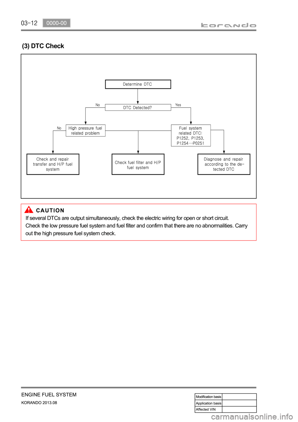
(3) DTC Check
If several DTCs are output simultaneously, check the electric wiring for open or short circuit.
Check the low pressure fuel system and fuel filter and confirm that there are no abnormalities. Carry
out the high pressure fuel system check.
Page 238 of 1336
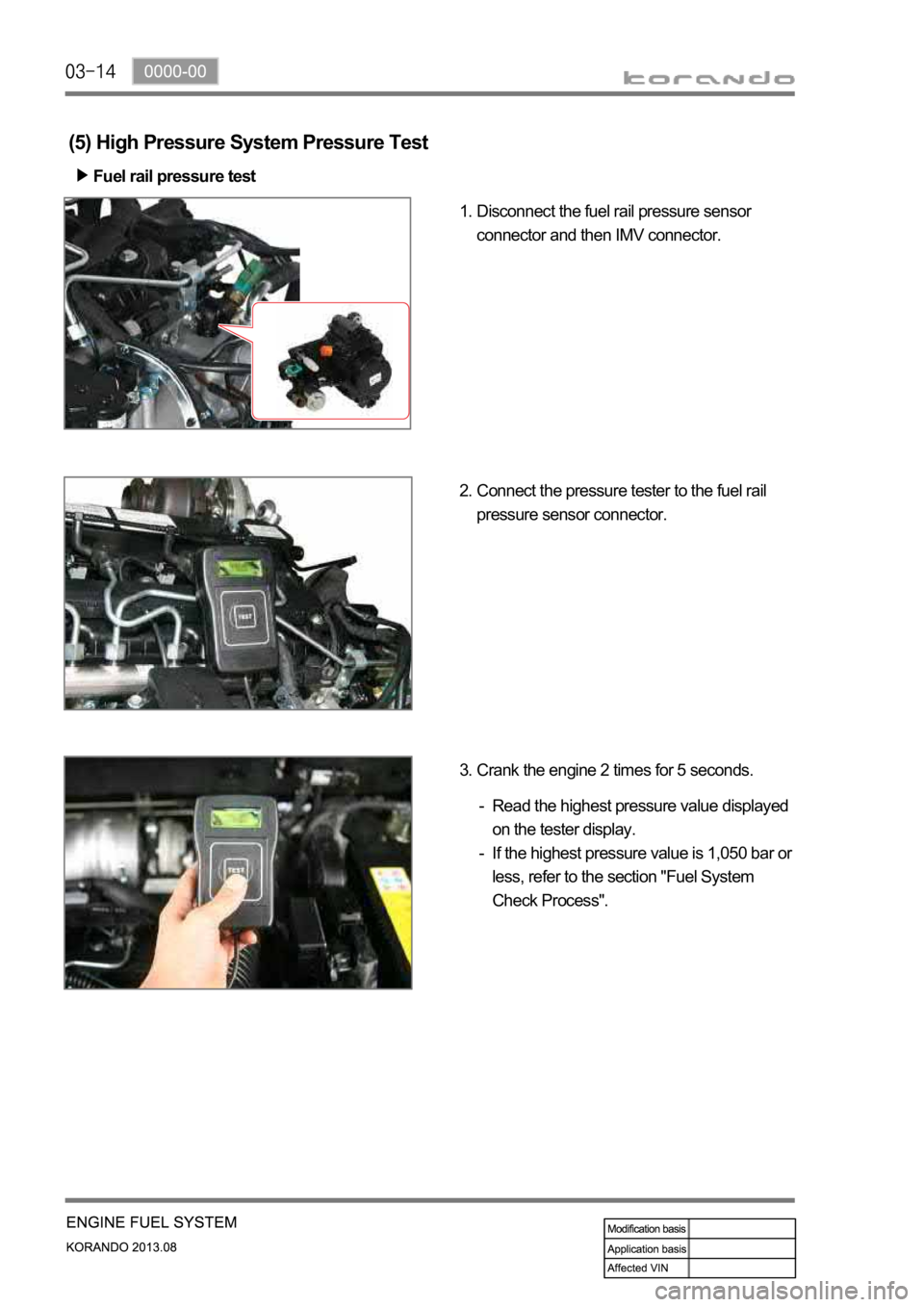
(5) High Pressure System Pressure Test
Fuel rail pressure test
Disconnect the fuel rail pressure sensor
connector and then IMV connector. 1.
Connect the pressure tester to the fuel rail
pressure sensor connector. 2.
Crank the engine 2 times for 5 seconds. 3.
Read the highest pressure value displayed
on the tester display.
If the highest pressure value is 1,050 bar or
less, refer to the section "Fuel System
Check Process". -
-