SSANGYONG MUSSO 2003 Service Manual
MUSSO 2003
SSANGYONG
SSANGYONG
https://www.carmanualsonline.info/img/67/57511/w960_57511-0.png
SSANGYONG MUSSO 2003 Service Manual
Page 435 of 1574
OM600 ENGINE MECHANICAL 1B3-171
OIL PAN1 Gasket ................................................... Replace
2 Upper Oil Pan
3 Combination Bolt ...................................... 10 Nm
4 Combination Bolt ...................................... 10 Nm
5 Gasket ................................................... Replace 6 Lower Oil Pan
7 Combination Bolt
...................................... 25 Nm
8 Drain Plug ................................................. 25 Nm
9 Washer Seal .......................................... Replace
10 Oil Pan
*Remove and install as numerical sequence. Notice Replace the washer seal with new one.
OM662LA OM661LA
Page 436 of 1574
1B3-172 OM600 ENGINE MECHANICAL Oil Circulation
Page 437 of 1574
OM600 ENGINE MECHANICAL 1B3-173
Oil Filter
a From Oil Pump
b To Main Oil Galleryc To Oil Pan
Page 438 of 1574
1B3-174 OM600 ENGINE MECHANICAL
OIL SPRAY NOZZLE
1 Fitting Sleeve
2 Oil Spray Nozzle
Disassembly Procedure
1. Remove oil pan or crankshaft.
2. Loose the bolt and then remove the nozzle.3 Combination Bolt ..................................... 10 Nm
A Oil Duct
Page 439 of 1574
OM600 ENGINE MECHANICAL 1B3-175
OIL PUMP
1 Oil Pump
2 Piston
3 Pressure Spring
4 Guide Pin5 Screw Plug
................................................ 50 Nm
6 Combination Bolt ...................................... 25 Nm
7 Oil Strainer
8 Bracket
Disassembly Procedure
1. Remove the oil pan.
2. Unscrew the mounting bolt of spracket.
Page 440 of 1574
1B3-176 OM600 ENGINE MECHANICAL
Tightening Torque 10 Nm
3. Unscrew the oil strainer bracket bolt.
4. Remove the oil pump.
5. Unscrew the screw plug and remove the relief valve.
6. Installation should follow the removal procedure in thereverse order.
Page 447 of 1574
OM600 ENGINE MECHANICAL 1B3-183
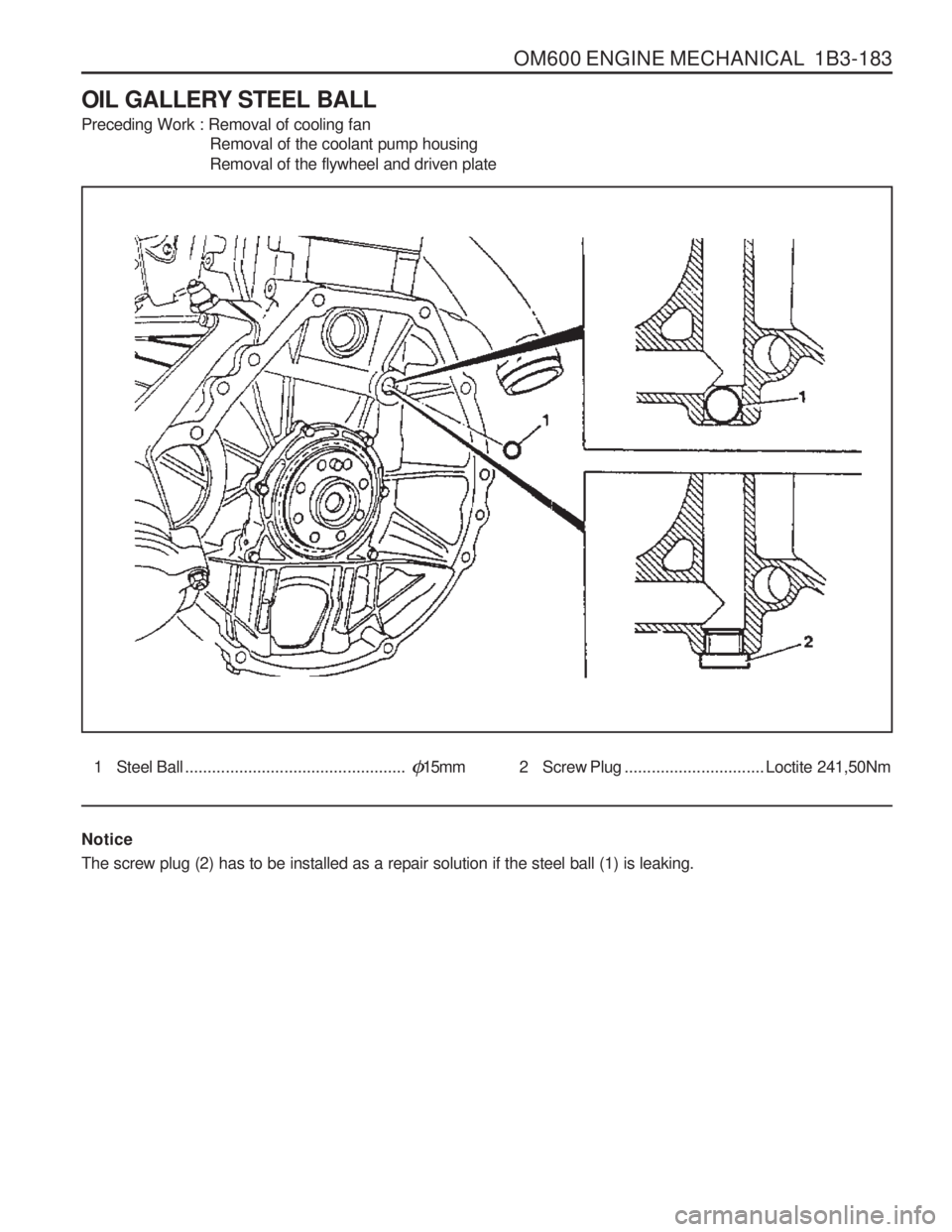
OIL GALLERY STEEL BALL Preceding Work : Removal of cooling fan Removal of the coolant pump housing Removal of the flywheel and driven plate
1 Steel Ball.................................................�15mm 2 Screw Plug ............................... Loctite 241,50Nm
Notice The screw plug (2) has to be installed as a repair solution if the steel ball (1) is leaking.
Page 449 of 1574
OM600 ENGINE MECHANICAL 1B3-185
Removal & Installation Procedure
1. Remove the timing case cover.
2. By inserting a round bar (6) approx. 0.7m from the back tothe front side through the oil gallery, knock out the steel balls (1,3). Notice Be careful not to damage the bores of the steel balls.
6 Shop-made tool
3. Thoroughly clean the bores of steel balls.
4. Place the steel ball (3) onto the drift (7) with a little grease and position to the bore and then tap until the drift stops.
Drift 601 589 08 15 00
5. Place the steel ball (1) onto the drift (7) with a little grease and position to the bore and then tap until the drift stops.
Drift 601 589 08 1500
6. Warm up the engine and check the oil for leaks.
Page 450 of 1574
1B3-186 OM600 ENGINE MECHANICAL Installation of Screw PlugNotice If steel ball leaks again, install the screw plug.
1. Remove the steel ball.
2. Tap thread into the bores of the oil gallery.
NoticeFront bore : M18 ´ 1.5, depth 10mm
Rear bore : M16 ´ 1.5, depth 14mm
3. Thoroughly clean the oil gallery.
4. Tighten the front plug (5) with seal (4).
5. Apply Loctite 241 and then tighten the rear plug (2).
Tightening Torque 50 Nm
Tightening Torque 50 Nm
Page 452 of 1574

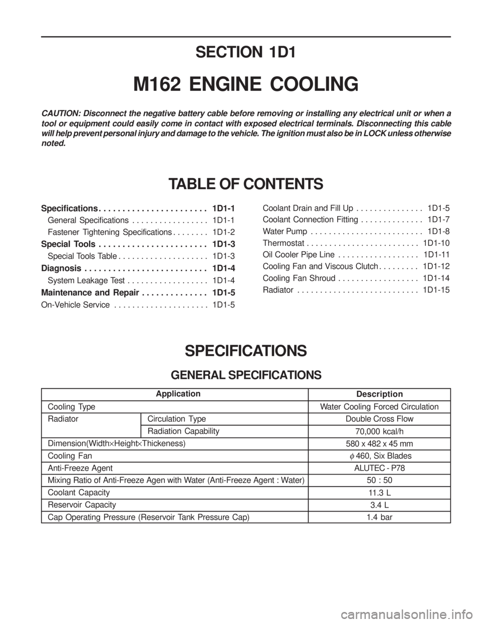
SECTION 1D1
M162 ENGINE COOLING
Specifications . . . . . . . . . . . . . . . . . . . . . . . 1D1-1General Specifications . . . . . . . . . . . . . . . . . 1D1-1
Fastener Tightening Specifications . . . . . . . . 1D1-2
Special Tools . . . . . . . . . . . . . . . . . . . . . . . 1D1-3 Special Tools Table . . . . . . . . . . . . . . . . . . . . 1D1-3
Diagnosis . . . . . . . . . . . . . . . . . . . . . . . . . . 1D1-4 System Leakage Test . . . . . . . . . . . . . . . . . . 1D1-4
Maintenance and Repair . . . . . . . . . . . . . . 1D1-5
On-Vehicle Service . . . . . . . . . . . . . . . . . . . . . 1D1-5Coolant Drain and Fill Up . . . . . . . . . . . . . . .
1D1-5
Coolant Connection Fitting . . . . . . . . . . . . . . 1D1-7
Water Pump . . . . . . . . . . . . . . . . . . . . . . . . . 1D1-8
Thermostat . . . . . . . . . . . . . . . . . . . . . . . . . 1D1-10
Oil Cooler Pipe Line . . . . . . . . . . . . . . . . . . 1D1-11
Cooling Fan and Viscous Clutch . . . . . . . . . 1D1-12
Cooling Fan Shroud . . . . . . . . . . . . . . . . . . 1D1-14
Radiator . . . . . . . . . . . . . . . . . . . . . . . . . . . 1D1-15
SPECIFICATIONS
GENERAL SPECIFICATIONS
CAUTION: Disconnect the negative battery cable before removing or installing any electrical unit or when a tool or equipment could easily come in contact with exposed electrical terminals. Disconnecting this cable will help prevent personal injury and damage to the vehicle. The ignition must also be in LOCK unless otherwisenoted.
TABLE OF CONTENTS
Description
Water Cooling Forced Circulation Double Cross Flow
70,000 kcal/h
580 x 482 x 45 mm
� 460, Six Blades
ALUTEC - P78
50 : 50
11.3 L 3.4 L
1.4 bar
Application
Cooling Type Radiator Dimension(Width ×Height ×Thickeness)
Cooling Fan Anti-Freeze Agent
Mixing Ratio of Anti-Freeze Agen with Water (Anti-Freeze Agent : Water)Coolant CapacityReservoir Capacity
Cap Operating Pressure (Reservoir Tank Pressure Cap)
Circulation Type Radiation Capability


