EGR SSANGYONG MUSSO 2003 User Guide
[x] Cancel search | Manufacturer: SSANGYONG, Model Year: 2003, Model line: MUSSO, Model: SSANGYONG MUSSO 2003Pages: 1574, PDF Size: 26.41 MB
Page 940 of 1574

AUTOMATIC TRANSMISSION 5A-81
Throttle Clearing
The leant throttle clearing routine uses the mode switch and gear lever. Carry out the following steps to complete the
automated throttle clearing procedure:
1. Switch ignition ‘ON ’ with handbrake applied and engine ‘OFF ’.
2. Select ‘M1 ’ and ‘WINTER ’ mode.
3. Move the T-bar to ‘M2 ’ and then select ‘NORMAL ’ or ‘POWER ’ mode.
4. Move the T-bar to ‘M3 ’ and then select ‘WINTER ’ mode.
Vehicle Coding
The vehicle coding is integrated as part of the diagnostic software. The coding applies to the following vehicle models: 1. 4WD Gasoline E32.
2. 4WD Gasoline 523
3. 4WD Gasoline 520.
4. 4WD Diesel D29NA.
5. 4WD Diesel D29LA.
6. 4WD Diesel D23LA.
7. RWD E20.
8. RWD E23.
Page 1212 of 1574

9A-10 BODY WIRING SYSTEM94 Seat Belt Switch (Driver)
95 Seat Belt Switch (Dirver)
96 Parking Brake Switch
97 Rear Cigarette Lighter
9 8 OVPR ................................................................. Gasoline E/G
99 LH Side Repeater ............................................... Rear Fog Lamp
100 Engine Wiring Connector
101 Engine Joint Connector
102 Engine Joint Connector ......................................Gasoline E/G
103 ECS Engine Wiring Connector ...........................Diesel E/G & Gasoline E/G with HFM ECU
104 ABD Engine Wiring Connector ...........................ABD 5.0
105 ABD Engine Wiring Connector ...........................ABD 5.0
105-1 ABS Engine Wiring Connector ............................ABS 5.0
106 Canister Purge Solenoid Valve ...........................Gasoline E/G with MSE ECU
106-1 Canister Purge Solenoid Valve ...........................E20 & E23 Gasoline E/G with FHM ECU
107 Econo/Standard Solenoid Valve .........................Gasoline E/G with Automatic Transmission
108 CO Potentio Meter .............................................. Gasoline E/G with HFM ECU & CO Potentio Meter
109 Front Wiper Motor 11 0 O 2 Sensor
........................................................... E20 or E23 Gasoline E/G
111 RH Side Repeater
112 Engine Wiring Connector
113 Vertical Sensor
114 Lateral Sensor
115 Diagnosis
11 6 Joint Box ............................................................. Gasoline E/G (E32)
117 Canister Purge Solenoid Valve ...........................E32 Gasoline E/G with HFM ECU
118 Led Antenna ...................................................... Rolling code type Immobilizer
119 E-key Connector ................................................ Gasoline E/G with Rolling Code Type Immobilizer
120 Receiver Unit ...................................................... Gasoline E/G with Rolling Code Type Immobilizer
121 Receiver Unit ...................................................... Gasoline E/G with Rolling Code Type Immobilizer
122 Receiver Antenna .............................................. Gasoline E/G with Rolling Code Type Immobilizer
123 Receiver Connector ........................................... Gasoline E/G with Rolling Code Type Immobilizer
124 ICU Connector .................................................... Gasoline E/G with Rolling Code Type Immobilizer
125 ICU ..................................................................... Gasoline E/G with TOD (MSE ECU 3.2 Engine Only)
126 CAN Line ............................................................ Gasoline E/G with TOD (MSE ECU 3.2 Engine Only)
127 TOD ................................................................... Gasoline E/G with TOD (MSE ECU 3.2 Engine Only)
128 TOD ................................................................... Gasoline E/G with TOD (MSE ECU 3.2 Engine Only)
129 Transfer Case Speed Sensor .............................Gasoline E/G with TOD (MSE ECU 3.2 Engine Only)
130 Engine Main Wiring Connector ...........................Gasoline E/G with MSE ECU
131 Remote Engine Start .......................................... Diesel E/G with A/T & Black Out Lamp
132 Remote Engine Start .......................................... Diesel E/G with A/T & Black Out Lamp
133 TCU .................................................................... Diesel E/G with BTRE A/T
134 TCU .................................................................... Diesel E/G with BTRE A/T
135 Ground 5 ............................................................ Diesel E/G
136 Start Protection Relay .........................................Diesel E/G with Rolling Code Type Immobilizer
137 EGR control unit ................................................. Diesel E/G
1 3 8 ICU 1 .................................................................. Diesel E/G with Rolling Code Type Immobilizer
1 3 9 ICU 2 .................................................................. Diesel E/G with Rolling Code Type Immobilizer
140 Injection Pump Valve Extension ..........................Diesel E/G with Rolling Code Type Immobilizer
141 Injection Pump Valve Extension ..........................Diesel E/G with Rolling Code Type Immobilizer
142 EGR Solenoid .................................................... Diesel E/G
143 ICU led ................................................................ Diesel E/G with Rolling Code Type Immobilizer
144 Immobilizer Solenoid Valve ..................................Diesel E/G with Crypto Type Immobilizer
147 Immobilizer Unit ................................................... Diesel E/G with Crypto Type Immobilizer
Page 1238 of 1574

9B-10 LIGHTING SYSTEM Head Lamp Focusing When using the beam setting device
1. The head lamp focus should be adjusted by using a properbeam setting device.
2. Adjust the head lamp focus by using Up/Down, Left/Right adjusting screws.
When using the screen
1. Put the vehicle on the leveling surface.
2. One person is needed to seat on the driver's seat without other loads(CVW) and check the tire pressure if it is in the specification.
3. The distance between the headlamp and the screen is 25m.
4. Draw the vertical line (crossing the center of each headlamp) on the screen.
5. Start the engine.
6. Check if the cut-off line of the headlamp on the screen is in the specification.
1 ) Left/right direction
- The degree of the cross point at the cut-off line of theheadlamp and the vertical line should be 15.
2 ) Up/down direction - The distance between the cut-off line of the headlampand the horizontal line should be 25cm.
7. Adjust the focus if the cut-off line of the headlamp is out of
the specification by using up/down, left/right adjusting screws. A : Up/down direction adjusting screwB : Left/right direction adjusting secrw
Page 1315 of 1574

MUSSO-SPORTS 1A-3
SUPPLEMENT
HUBER EGR
SYSTEM DESCRIPTION The following chart shows the relationship between the input and the output in Huber EGR control unit. Compared to traditional system that only operates theEGR valve with RPM sensor and Micro switch, the HuberEGR control unit bring big differences that of traditionalsystem on the functions.
Input Signal
RPM sensor (CPS)
EGR valve lift sensor
Throttle position sensor (TPS) - M/T
Shift lever position
Throttle position sensor (TPS)
Vehicle speed sensor(VSS) Basic input signal for EGR operation Engine cold or hot signal
Position signal of EGR valve that is triggered by vacuum modulator 1 Transfer the engine load signal to the control unit directly (manual transmission)
TCU (A/T)
EGR
Control
Unit
Coolant temperature sensor (CTS)
Solenoid valve (Control forvacuum modulator 2)
If the control unit determines it is in no-load sharp accel- eration mode after analyzing the input signals, this conver- sion type switch reduces the fuel consumption by cutting off the intake air pressure from
fuel injection ALDA and gen- erating the vacuum pressure. In no-load sharp acceleration
mode, Duty Control ( continu- ous precise control) is acti- vated according to the varia- tions of the input signals when the solenoid valve generates the vacuum pressure in ALDA.
Vacuum modulator 2
The opening value of the modulator is precisely con- trolled by input signals and programmed MAP, and the opening value of EGR valve is also changed by the varia- tions of vacuum pressure to EGR valve. The changed opening value is transferred to the control unit as input signal.
Vacuum modulator 1
TCU in automatic transmission equipped vehicle transfers the information such as driving conditions and speeds into the EGR control unit. EGR control unit uses the shift lever position and vehicle speed as important information for operating the solenoid valve during no-load sharp acceleration mode. In manual transmission, the signal of vehicle speed is transferred into the EGR control unit directly.
Clutch switch
In manual transmission, the clutch switch is the one of core elements to determine driving condition. Output Signal
EGR Control Unit
Page 1316 of 1574

1A-4 MUSSO-SPORTS
SUPPLEMENT
from vacuum pump
EGR valve
EGR control unit
KAA5A020
KAA5A020
KAA5A020
KAA5A020 EGR COMPONENTS EGR Unit
1. Location: behind passenger's side panel
2. Arrangement: 81-pin connector
3. Integrated self-diagnostic function (Scan-100: not
fixed)
4. Part number For automatic transmission: 28800-07100 For manual transmission: 28800-07000
Vacuum Modulator
1. Location: in front of intake manifold
2. Continuous precise control with the signals from EGR unit (PWM-Pulse With Modulation Control)
3. Rated voltage: 12 V
4. Operating voltage: 8 ~ 16 V
5. Resistance (at 20 °C): 15.4 ± 0.7 �
6. Operating range of vacuum (Duty control)
Vacuum modulator 1: 0 ~ 600 mbar
Vacuum modulator 2: 300 ~ 600 mbar
7. Modulator control
Vacuum modulator 1: for controlling EGR valve
Vacuum modulator 2: for controlling no-load sharp
acceleration (ALDA control)
not used connector
Vacuum modulator 1
(for controlling EGR valve)Vacuum modulator 2
(for controlling ALDA)
from vacuum pump
Vacuum modulator 1
Vacuum modulator 2
Solenoid valve
ALDAIntake
manifold
EGR control unit
Page 1317 of 1574

MUSSO-SPORTS 1A-5
SUPPLEMENT
KAA5A020
KAA5A020
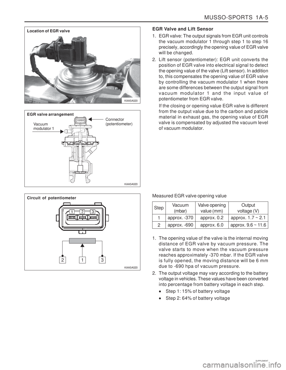
KAA5A020EGR Valve and Lift Sensor
1. EGR valve: The output signals from EGR unit controls
the vacuum modulator 1 through step 1 to step 16 precisely, accordingly the opening value of EGR valvewill be changed.
2. Lift sensor (potentiometer): EGR unit converts the position of EGR valve into electrical signal to detectthe opening value of the valve (Lift sensor). In additionto, this compensates the opening value of EGR valveby controlling the vacuum modulator 1 when thereare some differences between the output signal fromvacuum modulator 1 and the input value ofpotentiometer from EGR valve. If the closing or opening value EGR valve is different from the output value due to the carbon and paticlematerial in exhaust gas, the opening value of EGRvalve is compensated by adjusted the vacuum levelof vacuum modulator.
Measured EGR valve opening value Step 1 2
Vacuum(mbar)
approx. -370 approx. -690 Valve opening
value (mm)
approx. 0.2approx. 6.0 Output
voltage (V)
approx. 1.7 ~ 2.1
approx. 9.6 ~ 11.6
1. The opening value of the valve is the internal moving distance of EGR valve by vacuum pressure. The valve starts to move when the vacuum pressurereaches approximately -370 mbar. If the EGR valveis fully opened, the moving distance will be 6 mmdue to -690 hpa of vacuum pressure.
2. The output voltage may vary according to the battery voltage in vehicles. These values have been convertedinto percentage from battery voltage in each step.
Step 1: 15% of battery voltage
Step 2: 64% of battery voltage
Location of EGR valve EGR valve arrangement
Vacuum modulator 1 Connector (potentiometer)
Circuit of potentiometer
312
Page 1318 of 1574

1A-6 MUSSO-SPORTS
SUPPLEMENT
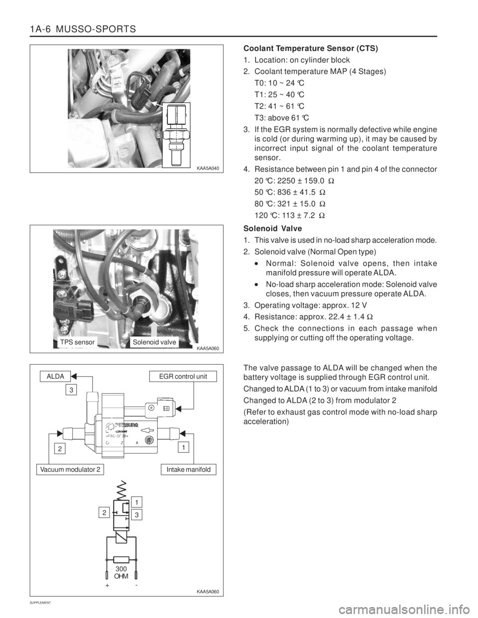
Coolant Temperature Sensor (CTS)
1. Location: on cylinder block
2. Coolant temperature MAP (4 Stages) T0: 10 ~ 24 °C
T1: 25 ~ 40 °C
T2: 41 ~ 61 °C
T3: above 61 °C
3. If the EGR system is normally defective while engine is cold (or during warming up), it may be caused by incorrect input signal of the coolant temperaturesensor.
4. Resistance between pin 1 and pin 4 of the connector 20 °C: 2250 ± 159.0 �
50 °C: 836 ± 41.5 �
80 °C: 321 ± 15.0 �
120 °C: 113 ± 7.2 �
KAA5A040 KAA5A060
KAA5A060Solenoid Valve
1. This valve is used in no-load sharp acceleration mode.
2. Solenoid valve (Normal Open type)
Normal: Solenoid valve opens, then intake
manifold pressure will operate ALDA.
No-load sharp acceleration mode: Solenoid valve
closes, then vacuum pressure operate ALDA.
3. Operating voltage: approx. 12 V
4. Resistance: approx. 22.4 ± 1.4 �
5. Check the connections in each passage when supplying or cutting off the operating voltage.
The valve passage to ALDA will be changed when the battery voltage is supplied through EGR control unit.
Changed to ALDA (1 to 3) or vacuum from intake manifold
Changed to ALDA (2 to 3) from modulator 2 (Refer to exhaust gas control mode with no-load sharp acceleration)
TPS sensorSolenoid valve
Intake manifold
ALDAEGR control unit
3
12
Vacuum modulator 2
2
1
3
300
OHM
+-
Page 1319 of 1574

MUSSO-SPORTS 1A-7
SUPPLEMENT
Throttle Position Sensor (TPS)
1. EGR unit receives TPS signal from TCU (A/T) or input
signal from pin 61 of EGR unit (M/T). The load value of engine is important signal because Huber EGRsystem make EGR valve operate in extended rangeexcept no-load sharp acceleration mode.
2. Resistance check
Disconnect the TPS sensor connector from fuelinjection pump and measure the entire resistancebetween pin 1 and pin 4. Specified value: 5 k � ± 20 %
Measure the resistance between pin 1 and pin 2 at no-load and full-load. Approx. 10 ~ 20 % of full resistance at no-load Approx. 70 ~ 85 % of full resistance at full-load
3. Voltage check
The supplied voltage to TPS from EGR unit (for
M/T) or TCU (for A/T) is approx. 5 V. 0.60 ± 0.2 V at no-load 3.85 ± 0.3 V at full-load
VACUUM LINE Installation of modulator and vacuum line (on-vehicle)
E GR n
Page 1320 of 1574

1A-8 MUSSO-SPORTS
SUPPLEMENT MAINTENANCE AND REPAIR
VACUUM PUMP AND VACUUM LINE This diagnosis procedure checks for vacuum leaks and actuator's operation while performing the actual control of EGR unit through vacuum lines in vacuum pump. The following special service tools should be used for this procedure.
001 589 73 21 00
Manual Vacuum Pump
Multi-Tester 201 589 13 21 00
Vacuum Tester
KAA5A2P0
KAA5A2R0 KAA5A2Q0
VACUUM LINE TEST Check the EGR system when the vehicle produces excessive exhaust gas. Check the vacuum lines for leaks and blocks. If there are not any faults, check the actuators controlled by EGR control unit. Install the tester in position according to the vacuum circuit diagram.
To prevent personal injury, beware of moving parts of engine.
Page 1321 of 1574

MUSSO-SPORTS 1A-9
SUPPLEMENT
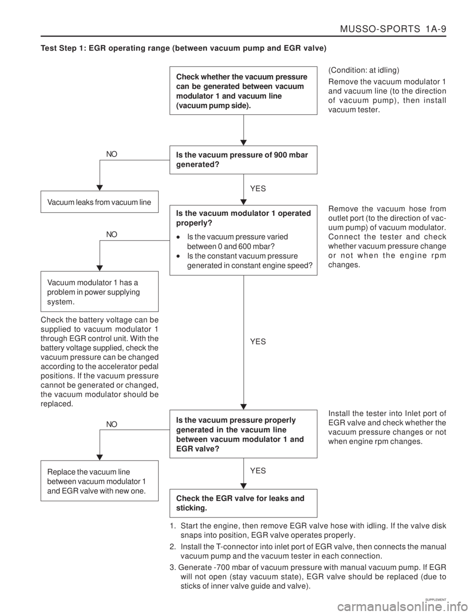
Test Step 1: EGR operating range (between vacuum pump and EGR valve)
(Condition: at idling) Remove the vacuum modulator 1 and vacuum line (to the directionof vacuum pump), then installvacuum tester.
Check whether the vacuum pressure can be generated between vacuum modulator 1 and vacuum line (vacuum pump side).
Is the vacuum pressure of 900 mbar generated?
Is the vacuum pressure properly generated in the vacuum line between vacuum modulator 1 and EGR valve?
Check the EGR valve for leaks and sticking.
Remove the vacuum hose from outlet port (to the direction of vac-uum pump) of vacuum modulator.Connect the tester and checkwhether vacuum pressure changeor not when the engine rpmchanges. Install the tester into Inlet port of EGR valve and check whether thevacuum pressure changes or notwhen engine rpm changes.
1. Start the engine, then remove EGR valve hose with idling. If the valve disk snaps into position, EGR valve operates properly.
2. Install the T-connector into inlet port of EGR valve, then connects the manual vacuum pump and the vacuum tester in each connection.
3. Generate -700 mbar of vacuum pressure with manual vacuum pump. If EGR will not open (stay vacuum state), EGR valve should be replaced (due tosticks of inner valve guide and valve).Vacuum leaks from vacuum line
NO
Is the vacuum modulator 1 operated properly?
Is the vacuum pressure varied
between 0 and 600 mbar?
Is the constant vacuum pressure
generated in constant engine speed?
Check the battery voltage can be supplied to vacuum modulator 1through EGR control unit. With thebattery voltage supplied, check thevacuum pressure can be changedaccording to the accelerator pedalpositions. If the vacuum pressurecannot be generated or changed,the vacuum modulator should bereplaced.
NO
Vacuum modulator 1 has a problem in power supplying system.
NO
Replace the vacuum line between vacuum modulator 1 and EGR valve with new one.
YES YES
YES