fuel cap SSANGYONG MUSSO 2003 User Guide
[x] Cancel search | Manufacturer: SSANGYONG, Model Year: 2003, Model line: MUSSO, Model: SSANGYONG MUSSO 2003Pages: 1574, PDF Size: 26.41 MB
Page 561 of 1574

M162 ENGINE CONTROLS 1F1-29
FUEL PRESSURE AND INTERNAL LEAKAGE TEST
01 Pressure Tester
02 Pressure Hose
03 Measuring Beaker
Preparation Connection of the Equipment
1. Turn the ignition switch to "OFF" position.
2. Remove the air cleaner cross pipe.
3. Remove the cap on fuel pressure test plug and connect the
pressure hose and pressure tester.
4. Prepare the beaker for measuring the amount of fuel.
Tools Required
103 589 00 21 00 Pressure Tester
119 589 04 63 00 Pressure Hose
Page 589 of 1574

M162 ENGINE CONTROLS 1F1-57
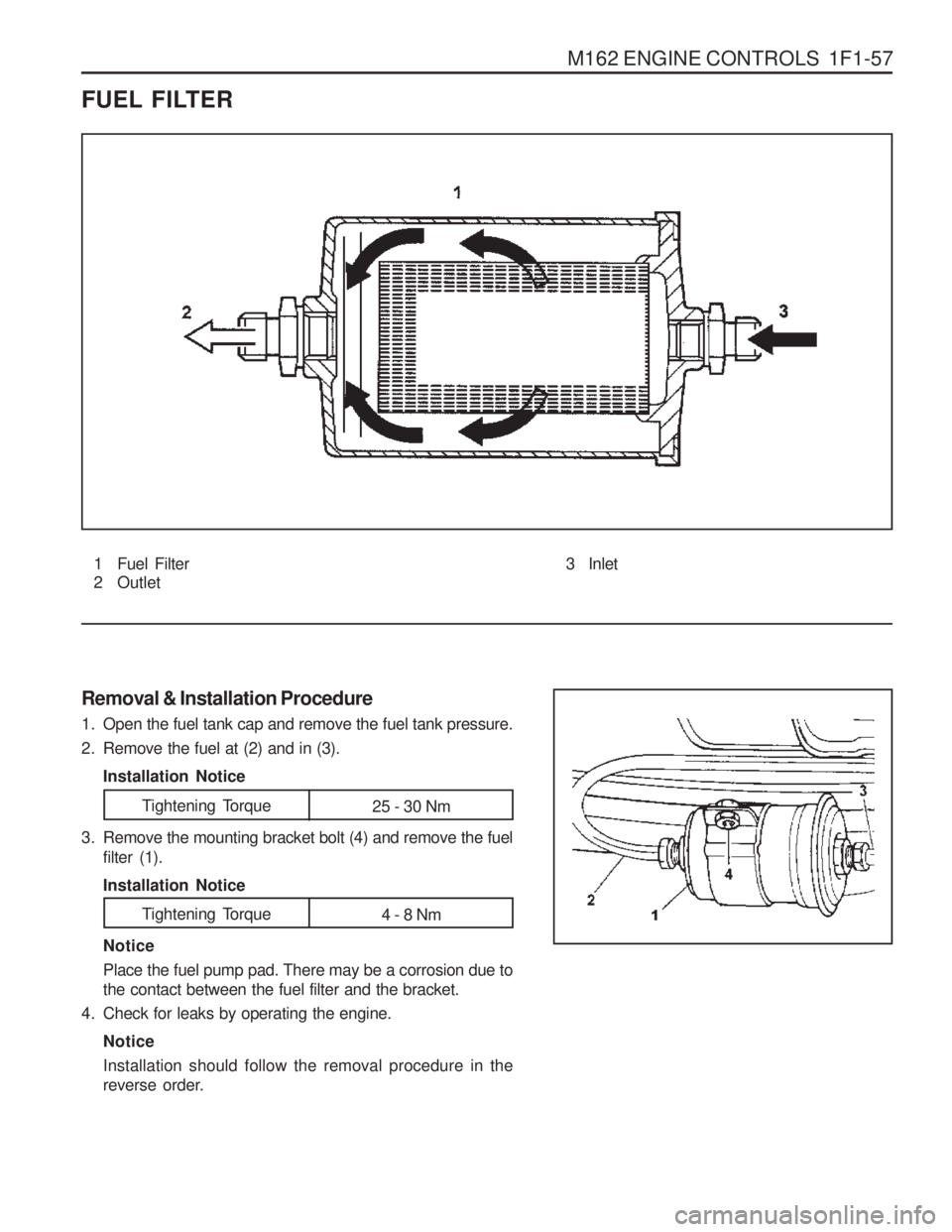
FUEL FILTER
1 Fuel Filter
2 Outlet
Removal & Installation Procedure
1. Open the fuel tank cap and remove the fuel tank pressure.
2. Remove the fuel at (2) and in (3). Installation Notice Notice Place the fuel pump pad. There may be a corrosion due to the contact between the fuel filter and the bracket.
4. Check for leaks by operating the engine.
Notice Installation should follow the removal procedure in the
reverse order.
3. Remove the mounting bracket bolt (4) and remove the fuel
filter (1). Installation Notice 3 Inlet
Tightening Torque
25 - 30 Nm
Tightening Torque 4 - 8 Nm
Page 592 of 1574

1F1-60 M162 ENGINE CONTROLS
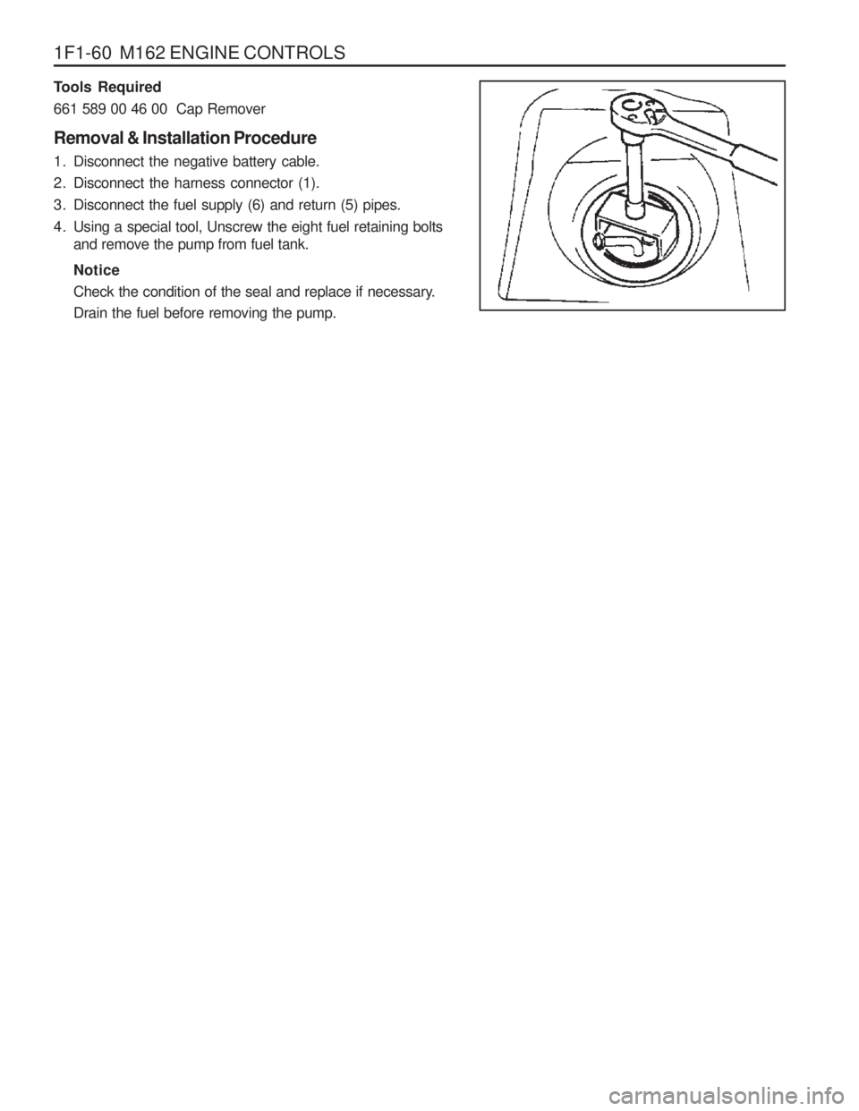
Tools Required 661 589 00 46 00 Cap Remover Removal & Installation Procedure
1. Disconnect the negative battery cable.
2. Disconnect the harness connector (1).
3. Disconnect the fuel supply (6) and return (5) pipes.
4. Using a special tool, Unscrew the eight fuel retaining boltsand remove the pump from fuel tank. Notice
Check the condition of the seal and replace if necessary. Drain the fuel before removing the pump.
Page 593 of 1574

M162 ENGINE CONTROLS 1F1-61
Notice Replace the fuel pump relay if the measured value is over 9A.
Notice Check the fuel filter and fuel line when the fuel delivery is not within specified value.
Measure the Current Consumption of Fuel Pump
1. Remove the fuel pump relay from fuse and relay box in trunk, and turn the ignition switch to "ON" position.
2. Using a multi-tester, measure the current consumption by connecting the terminal No.1 and No.3 of pump.
Measure the Fuel Delivery From the Fuel Pump
1. Disconnect the return pipe from fuel distributor and insert
the appropriate hose into it.
2 . Place the hose end into the beaker with the minimum capacity of 1Liter.
3. Turn the ignition switch to "ON" position.
4. Connect the terminal No.33 and No.5 of ECU with a service wire.
5. Measure the fuel delivery from the fuel pump.
1Liter/max.35sec.
Specifed Value
5 - 9A
Specifed Value
Page 596 of 1574

1F1-64 M162 ENGINE CONTROLS
VACUUM SYSTEM1 Purge Control Valve
2 Molded Hose
3 Insulator
4 Fuel Tube
5 Molded Hose
6 Idle Regulator
7 Resonance Flap
8 Intake Manifold
9 Fuel Pressure Regulator
10 Vacuum Line Rubber Hose11 Vacuum Tube(Gray, 270mm)
12 Molded Hose
13 Rubber Cap
18 Rubber Hose
19 Vacuum Tube(Brown or Black, 770mm)
20 Rubber Hose A To Canicter
Page 615 of 1574

1F3-4 OM600 ENGINE CONTROLS
FUEL TANK
1 Fuel Tank
2 The Sender of Fuel Tank
3 2-way Check Valve
4 Pre Filter
5 Front Fuel Filler Neck
6 Rear Fuel Filler Neck
7 Fuel Supply Tube 8 Fuel Return Tube
9 Filter Hose
10 Fuel Tank Hose
11 Fuel Filler Cap
12 Clip
13 Clip
Page 666 of 1574

M162 ENGINE INTAKE & EXHAUST 1G1-5
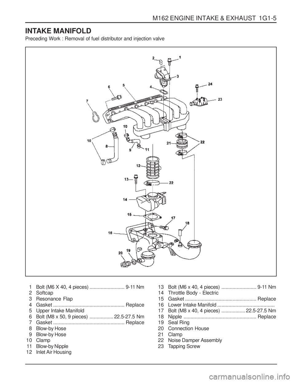
INTAKE MANIFOLD Preceding Work : Removal of fuel distributor and injection valve
1 Bolt (M6 X 40, 4 pieces)......................... 9-11 Nm
2 Softcap
3 Resonance Flap
4 Gasket ................................................... Replace
5 Upper Intake Manifold
6 Bolt (M8 x 50, 9 pieces) .................22.5-27.5 Nm
7 Gasket ................................................... Replace
8 Blow-by Hose
9 Blow-by Hose
1 0 Clamp
11 Blow-by Nipple
12 Inlet Air Housing 13 Bolt (M6 x 40, 4 pieces)
......................... 9-11 Nm
14 Throttle Body - Electric
15 Gasket ................................................... Replace
16 Lower Intake Manifold .........................................
17 Bolt (M8 x 40, 4 pieces) .................22.5-27.5 Nm
1 8 Nipple .................................................... Replace
19 Seal Ring
20 Connection House
2 1 Clamp
22 Noise Damper Assembly
23 Tapping Screw
Page 1367 of 1574

USAGE AND CAPACITY OF FUSES IN FUSE BOX 4-3
2. I/P FUSE BLOCK
1) POSITION OF RELAY AND FUSE 2) USAGE OF FUSE IN PASSENGER ROOM FUSE BOX
* 30 : BAT(+) Power Supply Through Ef1.
15A10A
10A15A10A
20A10A10A
10AST F110AIG1 F210AIG1 F3
ACC10AF4 B+30AF5
B+
(1) F6
F13
IG1
F20
15AF730AF1410AF21
F8F15F22
20AF915AF1610AF23
F10
B+
(2)
F17
F24
20AF1115AF1810A 15A
20AF1210AIG2 F19
30A
F25 F26
F27
85
87a3087
86
85
-3087
86
BE
L
85-
30
87
86
2) RELAY BOX
FRONT WIPERRELAY DEFOGGER
RELAY TURN SIGNAL
RELAY GSL : FUEL PUMP RELAYDSL : CIGAR LIGHTER, P/SOCKET RELAY A/T SHIFT LOCK
RELAY
8730
8685
8730
8685
8730
8685
8730
8685
A/T:PNP RELAY M/T:CLUTCH INTER LOCK RELAY SUNROOF
RELAY 'B' S/W
INTERLOCK RELAY POWER WINDER
RELAY 10A 10A10A10A30A15A15A10A20A20A20A20A30A15A15A10A 15A 10A10A10A10A10A10A10A15A30A
F1F2F3F4F5F6F7F8F9
F10 F11F12F14F15F16F17 F18 F19F20F21F22F23F24F25F26F27
Fuse No Capacity Usage
Starter Motor Relay Air BagABS/ABDOutside Mirror, AudioCigar Lighter, Power SocketStop LampHazard SwitchInteriorFuel Pump (Only GSL)TCCU/TOD, Power seatOVPR 1 (Only GSL)OVPR 4 (Only GSL)Heated GlassSun RoofRear Fog Lamp, Power ANT., ECSDLCFront Wiper & WasherRear Wiper & WasherTCCU/TCMBack Up Lamp, Turn Signal LampHead Lamp, Cluster OVPR 3 (Only GSL) Speed Sensor, Unit, Relay CoilNot UsedNot UsedNot Used
Power Supply
30 BAT(+)
ACC (15C) IGN2 (15A)
30 BAT (+)
IGN1 (15)
IGN1 (15)
SPARE
8730
8685
8730
8685
ECS
RELAY ABS WARNING
LAMP RELAY
8730
8685
Page 1368 of 1574

4-4 USAGE AND CAPACITY OF FUSES IN FUSE BOXSDM Chime BellImmobilizer UnitSticsRekesEBCM
4 Pin 4 Pin 4 Pin4 Pin4 Pin4 Pin4 Pin 4 Pin 3 Pin3 Pin
82330-05000 84190-05100 84150-0130084150-0130084150-0130084150-0130084150-01300 84150-01300 84130-0500084130-05000
Part Name Part Number
Remarks
Resistor W/Diode (GSL) A/C Compressor Relaly (DSL)A/C RelayCooling Fan - 1 RelayCooling Fan - 2 RelayFront Fog Lamp Relay Head Lamp Relay (Low) Head Lamp Relay (Hi)Illumination RelayHorn Relay
3. POSITION OF RELAY, CONTROL UNIT AND PARTS NUMBER
1) ENGINE ROOM FUSE BLOCK
2) RELAY BOX ABOVE I.P FUSE BLOCK
5 Pin 5 Pin 3 Pin5 Pin5 Pin4 Pin4 Pin 4 Pin 4 Pin 4 Pin 4 Pin 4 Pin
84210-05001 84210-05001 84410-05100
66182253386618225338
84150-0130084150-01300 84150-01300 84150-01300 84150-0130084150-0130084190-05100
Part Name Part Number Remarks
Front Wiper Relay Defogger RelayTurn Signal Lamp RelayFuel Pump Relay (GSL)Cigar Lighter, P/socket Relay (DSL)A/T Shift lock Relay PNP Relay Sun Roof RelayA/T "B" Switch Interlock Relay Power Window Relay ECL RelayABS Warning Lamp Relay
3) CONTROL UNIT
Below The Audio
Beside The SDM
Behind the Wiper Switch Upper The Accelerator Upper The Stics
I/P Center Console Floor Panel
8690005800 8661005000869500580087110058008716105000
4891005000X
Part Name Part Number Remarks