radiator SSANGYONG MUSSO 2003 Owner's Manual
[x] Cancel search | Manufacturer: SSANGYONG, Model Year: 2003, Model line: MUSSO, Model: SSANGYONG MUSSO 2003Pages: 1574, PDF Size: 26.41 MB
Page 468 of 1574

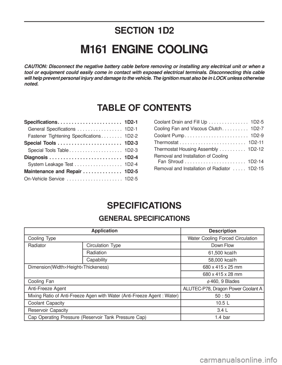
Circulation Type RadiationCapabilitySECTION 1D2
M161 ENGINE COOLING
Specifications . . . . . . . . . . . . . . . . . . . . . . . 1D2-1
General Specifications . . . . . . . . . . . . . . . . . 1D2-1
Fastener Tightening Specifications . . . . . . . . 1D2-2
Special Tools . . . . . . . . . . . . . . . . . . . . . . . 1D2-3
Special Tools Table . . . . . . . . . . . . . . . . . . . . 1D2-3
Diagnosis . . . . . . . . . . . . . . . . . . . . . . . . . . 1D2-4 System Leakage Test . . . . . . . . . . . . . . . . . . 1D2-4
Maintenance and Repair . . . . . . . . . . . . . . 1D2-5
On-Vehicle Service . . . . . . . . . . . . . . . . . . . . . 1D2-5Coolant Drain and Fill Up . . . . . . . . . . . . . . .
1D2-5
Cooling Fan and Viscous Clutch . . . . . . . . . . 1D2-7
Coolant Pump . . . . . . . . . . . . . . . . . . . . . . . . 1D2-9
Thermostat . . . . . . . . . . . . . . . . . . . . . . . . . 1D2-11
Thermostat Housing Assembly . . . . . . . . . . 1D2-12
Removal and Installation of Cooling Fan Shroud . . . . . . . . . . . . . . . . . . . . . . . 1D2-14
Removal and Installation of Radiator . . . . . 1D2-15
SPECIFICATIONS
GENERAL SPECIFICATIONS
CAUTION: Disconnect the negative battery cable before removing or installing any electrical unit or when a tool or equipment could easily come in contact with exposed electrical terminals. Disconnecting this cable will help prevent personal injury and damage to the vehicle. The ignition must also be in LOCK unless otherwisenoted.
TABLE OF CONTENTS
Description
Water Cooling Forced Circulation Down Flow
61,500 kcal/h 58,000 kcal/h
680 x 415 x 25 mm680 x 415 x 28 mm
� 460, 9 Blades
ALUTEC-P78, Dragon Power Coolant A 50 : 5010.5 L 3.4 L
1.4 bar
Application
Cooling TypeRadiator Dimension(Width ×Height ×Thickeness)
Cooling Fan Anti-Freeze Agent
Mixing Ratio of Anti-Freeze Agen with Water (Anti-Freeze Agent : Water) Coolant Capacity Reservoir Capacity
Cap Operating Pressure (Reservoir Tank Pressure Cap)
Page 472 of 1574

M161 ENGINE COOLING 1D2-5
MAINTENANCE AND REPAIR
ON-VEHICLE SERVICE
COOLANT DRAIN AND FILL UP Draning & Filling up Procedure 1. Loosen the cap a little and release pressure and remove the cap. NoticeFor the risk of scalding, the cap must not be opened unless the coolant temperature is below 90oC.
2. Loosen the radiator lower drain cock and drain the coolant.
Notice
Collect coolant by using a proper container.
3. Drain the coolant from the crankcase by inserting a hose(dia. 14mm) onto the drain bolt on the side of crankcase (exhaust manifold) and by loosening the plug. Notice
� Just loosen the drain plug to drain the coolant and do
not remove the plug completely.
� Collect coolant by using proper container.
Page 473 of 1574

1D2-6 M161 ENGINE COOLING
4. After complete draining of the coolant, remove the hoseconnector to drain plug and reinstall the drain plug. Installation Notice
5. Tighten the radiator lower drain cock.
6. Remove the de-aeration hose clamp in the coolant pumpand remove the de-aeration hose.
7. Fill up the coolant through the coolant reservoir tank. Notice
� Match the anti-freeze and the water ratio to 50 : 50.
� Supplement the coolant until the coolant overflows to the deaeration hose.
Tightening Torque 30 Nm
8. Insert the de-aeration hose and completely tighten the clamp.
9. Check the coolant level in the coolant reservoir tank.
10. Warm up(until thermostat is opened) the engine and recheck the coolant level in the reservoir tank and fill up
the coolant if necessary.
Page 478 of 1574

M161 ENGINE COOLING 1D2-11
THERMOSTAT
Removal & Installation Procedure
1. Drain the coolant from the radiator.
2. Loosen the hose mounting clip and remove the coolant hose (3, 4).
3. Unscrew the three bolts (1) and remove the thermostat cover assembly from thermostat housing.Installation Notice Do not separate the thermostat cover and thermostat.
4. Replace the O-ring if necessary.
5. Check the leakage in the cooling system.
Tightening Torque 9 - 11 Nm
1 Bolt (M6 X 25, 3 pieces)
........................ 9 -11 Nm
2 Thermostat Cover
3 De-aeration Hose 4 Coolant Outlet Hose
5 Thermostat
6 O-ring
Page 482 of 1574

M161 ENGINE COOLING 1D2-15
REMOVAL AND INSTALLATION OF RADIATOR Preceding Work : Removal of cooling fan shroud
1 Inlet Hose
2 Hose (to Engine)
3 Hose (to 3-way Connector)
4 Make-up Hose (to Coolant Reservoir)
5 3-way Connector
6 Automatic Transmission Oil Cooling Hose (A/T Equippend Vehicle) 7 Bolt (M6 X 20, 4 pieces)
...........................3-7 Nm
8 Insulator
9 Radiator Bracket
10 Radiator
Page 483 of 1574

1D2-16 M161 ENGINE COOLING Removal & Installation Procedure1. Drain coolant from the radiator.
2. Remove the coolant thermo connector from the radiator.
3. Remove the each coolant hoses.
Tightening Torque 14 Nm
4. Remove the automatic transmission oil cooling hose.
Installation Notice
5. Unscrew the bolts from radiator bracket and remove the bracket and insulator. Installation Notice
Tightening Torque 3 - 7 Nm
6. Remove the radiator upper mounting bolts and then remove the bracket and insulator.
7. Remove the radiator.
8. Check the radiator pin for crack, damage, leakage and bending and replace if necessary.
9. Installation should follow the removal procedure in the reverse order.
10. Berform the cooling system leakage test.
Page 484 of 1574

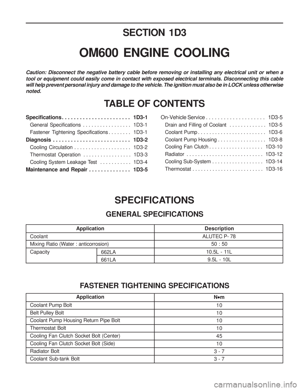
SECTION 1D3
OM600 ENGINE COOLING
Specifications . . . . . . . . . . . . . . . . . . . . . . . 1D3-1General Specifications . . . . . . . . . . . . . . . . . 1D3-1
Fastener Tightening Specifications . . . . . . . . 1D3-1
Diagnosis . . . . . . . . . . . . . . . . . . . . . . . . . . 1D3-2 Cooling Circulation . . . . . . . . . . . . . . . . . . . . 1D3-2
Thermostat Operation . . . . . . . . . . . . . . . . . 1D3-3
Cooling System Leakage Test . . . . . . . . . . . 1D3-4
Maintenance and Repair . . . . . . . . . . . . . . 1D3-5 On-Vehicle Service . . . . . . . . . . . . . . . . . . . .
1D3-5
Drain and Filling of Coolant . . . . . . . . . . . . . 1D3-5
Coolant Pump . . . . . . . . . . . . . . . . . . . . . . . . 1D3-6
Coolant Pump Housing . . . . . . . . . . . . . . . . . 1D3-8
Cooling Fan Clutch . . . . . . . . . . . . . . . . . . . 1D3-10
Radiator . . . . . . . . . . . . . . . . . . . . . . . . . . . 1D3-12
Cooling Sub-System . . . . . . . . . . . . . . . . . . 1D3-14
Thermostat . . . . . . . . . . . . . . . . . . . . . . . . . 1D3-16
TABLE OF CONTENTS
Caution: Disconnect the negative battery cable before removing or installing any electrical unit or when a tool or equipment could easily come in contact with exposed electrical terminals. Disconnecting this cable will help prevent personal injury and damage to the vehicle. The ignition must also be in LOCK unless otherwisenoted.
Application
Coolant
Mixing Ratio (Water : anticorrosion) Capacity
Description
ALUTEC P- 78 50 : 50
10.5L - 11L 9.5L - 10L
SPECIFICATIONS
GENERAL SPECIFICATIONS
Application
Coolant Pump Bolt Belt Pulley BoltCoolant Pump Housing Return Pipe BoltThermostat Bolt Cooling Fan Clutch Socket Bolt (Center) Cooling Fan Clutch Socket Bolt (Side)Radiator BoltCoolant Sub-tank BoltN
m
10 101010 45 10
3 - 73 - 7
FASTENER TIGHTENING SPECIFICATIONS
662LA 661LA
Page 485 of 1574

1D3-2 OM600 ENGINE COOLING
COOLING CIRCULATIONA Thermostat
B Radiator
D From Heater
E Hose
G Deaeration Line
H Reservoir
DIAGNOSIS
Page 486 of 1574

OM600 ENGINE COOLING 1D3-3
THERMOSTAT OPERATION Operation
1. At warming upValve closes until temperature of coolant reaches to 85 °C.
B. From Radiator
C. From Crankcase
D. To Crankcase
2. At partial opening. Valve opens partially as temperature of coolant is maintained between 85-100 °C.
3. At full opening. Valve opens full as temperature of coolant is more then 100 °C.
Page 487 of 1574

1D3-4 OM600 ENGINE COOLING
COOLING SYSTEM LEAKAGE TEST
Tools Required
124 589 15 21 00 Tester
Test
1. Loosen the pressure cap by 1 notch and remove the capafter. Notice Do not remove radiator cap when coolant is above 90 °C.
2. Add the coolant to the arrow mark of coolant reservoir.
3. Connect the special tool to the injector of reservoir and apply 1.4bar pressure. Tester 124 589 15 21 00
4. If the pressure on the tester drops, check the hose, pipe and leakage and, replace or retighten.