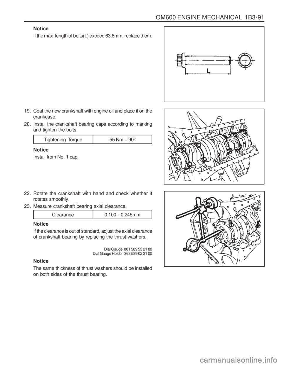
engine SSANGYONG MUSSO 2003 Service Manual
[x] Cancel search | Manufacturer: SSANGYONG, Model Year: 2003, Model line: MUSSO, Model: SSANGYONG MUSSO 2003Pages: 1574, PDF Size: 26.41 MB
Page 348 of 1574

OM600 ENGINE MECHANICAL 1B3-83
CRANKSHAFT
Preceding Work : Removal of the end coverRemoval of the piston Removal of the crankshaft sprocket
3 Crankshaft Main Bearing Shells (Upper)
4 Trust Bearings (Upper)
5 Crankshaft
6 Crankshaft Main Bearing Shells (Lower) 7 Thrust Bearings (Lower)
8 Crankshaft Bearing Cap
9 Crankshaft Bearing Cap (Fit Bearing)
10 12-sided Stretch Bolts ....................... 55Nm + 90°
Tools Required 001 589 53 21 00 Dial Gauge363 589 02 21 00 Dial Gauge Holder366 589 00 21 05 Extension
Page 349 of 1574

1B3-84 OM600 ENGINE MECHANICAL3 Crankshaft Main Bearing Shells (Upper)
4 Thrust Bearings (Upper)
5 Crankshaft
6 Crankshaft Main Bearing Shells (Lower)
7 Thrust Bearings (Lower)
A Radial Bearings
B Radial and Axial Bearings (Thrust Bearing)
Notice The gaps between the bearing shell and bore and between the bearing shell and journal are different
each other. Refer to service data.
Thrust Washer and Bearing Arrangement OM662LA Engine
Page 350 of 1574

OM600 ENGINE MECHANICAL 1B3-85
3 Crankshaft Main Bearing Shells (Upper)
4 Thrust Bearings (Upper)
5 Crankshaft
6 Crankshaft Main Bearing Shells (Lower)
7 Thrust Bearings (Lower)A Radial Bearings
B Radial and Axial Bearings (Thrust Bearing)
Notice The gaps between the bearing shell and bore and between the bearing shell and journal are different
each other. Refer to service data.
OM661LA Engine
Page 351 of 1574

1B3-86 OM600 ENGINE MECHANICAL
24.500 - 24.533 24.600 - 24.633 24.700 - 24.733 24.900 - 24.93325.000 - 25.033New
Limit New
Limit
Radial clearances Axial clearances Crankshaft bearing
journal diameter
Crankshaft Standard and Repair Sizes
Standard size 50.950 - 57.965
journal width
24.500 - 24.533 24.600 - 24.63324.700 - 24.73324.900 - 24.93325.000 - 25.033
-Thrust bearing journal diameter
47.950 - 47.965
Thrust bearing
47.700 - 47.715 47.450 - 47.650 47.200 - 47.215 46.950 - 46.965
57.500 - 57.71557.450 - 57.465 57.200 - 57.215 56.950 - 56.965
Repair size 1Repair size 2 Repair size 3 Repair size 4
Bearing Clearances
Thrust bearingCrankshaft bearing
0.026 - 0.068 Max. 0.080 - -
0.027 - 0.051
Max. 0.070
0.100 - 0.254
Max. 0.300
Matching Fit Bearing Journal Width to Thrust Bearings
Fit bearing journal width Thrust bearings thickness
2.15 2.202.252.352.40
Notice
� Measure crankshaft axial clearance and adjust with proper thrust Bearing.
� The same thickness of washer must be installed on both sides of the fit bearing. mm mm mm
Page 352 of 1574

OM600 ENGINE MECHANICAL 1B3-87
bearing shell
Matching Crankshaft Bearing Shells to Basic Bearing Bore in Crankshaft Matching Crankshaft Bearing Shells to Basic Bearing Journal of Crankshaft
Marking of basic bearing bore in lowerColor code of relevant crankshaft
parting surface 1 punch mark or blue
2 punch marks or yellow 3 punch marks or red bearing shell
Blue or white-blue
Yellow or white-yellowRed or white-red
Marking of bearing journals on crank websColor code of relevant crankshaft
Blue or white-blue
Yellow or white-blue Red or white-blue Blue or white-blue
Yellow or white-yellow Red or white-red
Page 353 of 1574

1B3-88 OM600 ENGINE MECHANICAL Removal & Installation Procedure
1. Remove the bearing cab bolt.
2. Remove the bearing caps (8).NoticeThe crankshaft bearing caps are marked with stamped numbers. Remove the bearing cap from the vibration damper side.
3. Remove the crankshaft bearing caps (9) and lower thrust bearings (7).
4. Remove the lower thrust bearings (6) from the bearing cap (9).
5. Remove the crankshaft (5).
6. Remove the upper thrust bearings(4).
7. Remove the upper bearing shells (3) from crankcase.
Page 354 of 1574

OM600 ENGINE MECHANICAL 1B3-89
14. Measure crankshaft bearing journal diameter (F).Notice When measured in A and B, the runout should not exceed 0.010mm.
8. Thoroughly clean the oil gallery.
9. Select a proper new bearing shells with reference to table.
10. Coat the new bearing shells with oil and insert into the crankcase and into the crankshaft bearing caps. Notice Do not mix up upper and lower crankshaft bearing shells.
11. Install the bearing caps according to marking and tighten the 12-sided stretch bolts.
Tightening Torque 35 - 40 Nm
Notice No. 1 is vibration damper side.
12. Measure crankshaft bearing diameters (E).
Extension 366 589 00 21 05
13. Measure at 3 points (A, B and C) and if the average value of B and C is less than A ’s value, the average value of B
and C is the mean value and if more than A ’s value, A ’ s
value is the mean value.
Page 355 of 1574

1B3-90 OM600 ENGINE MECHANICAL
15. Measure radial clearance of crankshaft bearing (G).
Clearance ‘G’ 0.027 - 0.051mm
Notice If ‘G’ is out of standard, replace the bearing shells and
adjust the radial clearance of crankshaft bearing.Example) Measured value ‘E’ = 57.700mm
Measured value ‘F’ = 57.659mm
Clearance ‘G’ = 0.041mm
16. Remove the crankshaft bearing cap.
17. Measure width of thrust bearing journal (H) and adjust with
proper thrust bearings (see table). Notice The same thickness of thrust washers should be installed on both sides of the thrust bearing.
18. Coat the upper thrust bearing (4) with oil and insert intothe crankcase so that the oil grooves are facing the crank webs (arrow).
19. Coat the lower thrust bearing (7) with oil and insert into the crankshaft bearing cap so that the oil grooves are facingthe crank webs (arrow). Notice The retaining lugs should be positioned in the grooves (arrow).
Page 356 of 1574

OM600 ENGINE MECHANICAL 1B3-91
Notice If the max. length of bolts(L) exceed 63.8mm, replace them.
19. Coat the new crankshaft with engine oil and place it on the crankcase.
20. Install the crankshaft bearing caps according to marking and tighten the bolts.
Tightening Torque 55 Nm + 90 °
Notice Install from No. 1 cap.
22. Rotate the crankshaft with hand and check whether it rotates smoothly.
23. Measure crankshaft bearing axial clearance.
Clearance 0.100 - 0.245mm
Notice If the clearance is out of standard, adjust the axial clearance of crankshaft bearing by replacing the thrust washers.
Dial Gauge 001 589 53 21 00
Dial Gauge Holder 363 589 02 21 00
Notice The same thickness of thrust washers should be installed on both sides of the thrust bearing.
Page 357 of 1574

1B3-92 OM600 ENGINE MECHANICAL
28. Remove the connecting rod bearing cap.
29. Install the piston.
30. Rotate the crankshaft by hand and check whether it rotatessmoothly.
31. If the bearings are damaged,
- replace the oil presser relief valve. - clean the oil pump and oil filter housing carefully and
replace the hose if necessary. Notice After assembling the engine, check the camshaft timing, adjust the start of fuel injection and check the TDC sensorbracket setting.
32. Fill oil and run the engine and then check the oil pressure and oil level. Notice Install the original oil filter element and then change the engine oil and oil filter element after 1,000 - 1,500km.
27. Measure the radial clearance (L) of the connecting rod
bearing. Example) Measured value ‘J’ = 47.700mm
Measured value ‘K’ = 47.653mm
Clearance ‘L’ = 0.047mm
Radial Clearance ‘L’0.026 - 0.068mm
Notice If the clearance is out of standard, adjust the radial clearance of connecting rod bearing by replacing theconnecting rod bearing shells.
26. Measure connecting rod bearing journal diameter (K).
Notice Refer to measurement of the crankshaft bearing journal
diameter.
24. Insert the new connecting rod bearing shells into theconnecting rod and connecting rod bearing cap and tighten
the 12-sided stretch bolts (11).
25. Measure inner diameter of connecting rod bearing.
Tightening Torque 40 Nm + 90 °