SSANGYONG MUSSO 2003 Service Manual
MUSSO 2003
SSANGYONG
SSANGYONG
https://www.carmanualsonline.info/img/67/57511/w960_57511-0.png
SSANGYONG MUSSO 2003 Service Manual
Page 308 of 1574
OM600 ENGINE MECHANICAL 1B3-43
18. Disconnect the booster hose connected to intake manifold.
19. Remove the intake manifold and gasket.
20. Remove the cylinder head cover and gasket with the blow-by gas hose.
21. Disconnect the glow plug cables.
Page 309 of 1574
1B3-44 OM600 ENGINE MECHANICAL
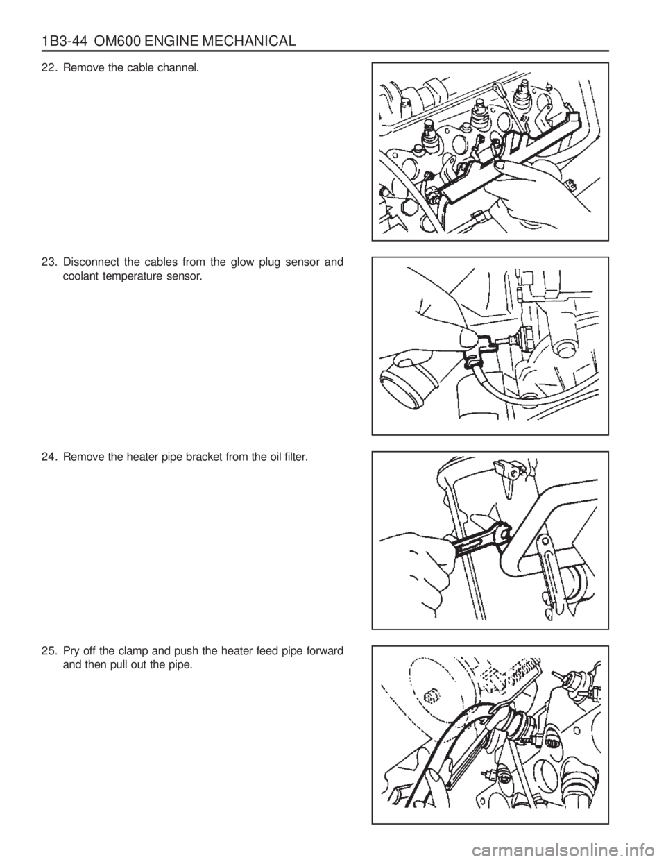
22. Remove the cable channel.
23. Disconnect the cables from the glow plug sensor andcoolant temperature sensor.
24. Remove the heater pipe bracket from the oil filter.
25. Pry off the clamp and push the heater feed pipe forward and then pull out the pipe.
Page 310 of 1574
OM600 ENGINE MECHANICAL 1B3-45
26. Disconnect the fuel lines from the fuel filter.
27. Disconnect the fuel lines from the injection pump.
28. Remove the fuel filter(35).
29. Remove the fuel injection nozzle(12) and nozzlewasher(11).
Socket Wrench Insert 001 589 65 09 00
Page 311 of 1574
1B3-46 OM600 ENGINE MECHANICAL
30. Rotate the crankshaft and set the no.1 cylinder at TDC.Notice Do not rotate the crankshaft to the opposite direction of engine revolution.
31. Place alignment marks on the camshaft gear and timing chain.
32. Ensure that the camshaft and the bearing cap marking are aligned.
33. Remove the starter motor and install the engine lock onto the flywheel ring gear.
Engine Lock 602 589 00 40 00
Page 312 of 1574
OM600 ENGINE MECHANICAL 1B3-47
34. Remove the turbocharger.
35. Remove the exhaust manifold and gasket.
36. Remove the chain tensioner and seal.
37. Remove the bolt and separate the drive sprocket(21).Notice During removal, be careful not to drop the sprocket and chain into the timing case. Carefully pull off the chain and then pull out the sprocket.
Page 313 of 1574
1B3-48 OM600 ENGINE MECHANICAL
38. Remove the camshaft bearing cap bolts according to thenumerical sequence. Notice Remove the No.1 bolts first and then remove the No. 2 bolts. Do not remove the bolts at a time completely butremove them step by step evenly or camshaft can beseriously damaged.
OM662LA
39. Remove the bearing caps and then pull out the camshaft(20) upward. Notice
Be careful not to miss the locking washer.
40. Remove the locking washer. Notice
Check the locking washer and replace if necessary.
OM661LA
Page 314 of 1574
OM600 ENGINE MECHANICAL 1B3-49
41. Remove the bolt(32).
42. Separate the spring and pull out the tensioning lever(31).
43. Pry off the closing cover. Remove the bolt and then removethe idle pulley.
44. Using the sliding hammer(36) and the threaded pin(37), pull out the sliding rail pins(25, 26) and remove the sliding rail(24).
Sliding Hammer 116 589 20 33 00Threaded Pin 116 589 02 34 00
Page 315 of 1574
1B3-50 OM600 ENGINE MECHANICALOM 662LA
46. Disconnect the vacuum pipe from thermo valve.
47. Remove the socket bolts(13) of the chain box.
T Type Socket Wrench 116 589 03 07 00Magnetic Bar 102 589 03 40 00
48. Remove the cylinder head bolts in numerical se-quence. Cylinder Head Bolt Wrench 601 589 00 10 00
45. Remove the vacuum line from the vacuum pump.
Page 316 of 1574
OM600 ENGINE MECHANICAL 1B3-51
49. Remove the cylinder head(2) and gasket(3).
OM 661LA
Page 317 of 1574
1B3-52 OM600 ENGINE MECHANICALLength(L)
Assembly Procedure
1. Replace the cylinder head gasket.
2. Install the cylinder head onto the crankcase.
Notice Align the cylinder head holes with the guide pins.
3. Measure the length(L) of cylinder head bolts. Notice If the max. length is exceeded, replace the bolts.
Thread Dia. Max. Limit(L)
M10 M10 M1080mm
102mm 115mm 82mm
104mm 117mm
when new
4. Coat the head contact surface of bolts and thread with oil
and insert them as shown. - Cylinder head bolts arrangement
Bore 1 ........................................... M10 ×
80
2 ........................................... M10 × 102
3 ........................................... M10 × 11 5
4 ........................................... M 8 × 50
5 ........................................... M 8 × 80 OM662LA


