light SSANGYONG MUSSO 2003 Owner's Guide
[x] Cancel search | Manufacturer: SSANGYONG, Model Year: 2003, Model line: MUSSO, Model: SSANGYONG MUSSO 2003Pages: 1574, PDF Size: 26.41 MB
Page 1023 of 1574

5B-34 MANUAL TRANSMISSION
COUNTER SHAFT Disassembly Procedure
1. Using a hydraulic press and special tool, remove the frontbearing assembly from the counter shaft.
2. Check and clean all removed parts and replace if necessary. Assembly Procedure
1. Using a hydraulic press and installer, press the front bearing assembly onto the counter shaft.
2. Install is as follows : � Install a new O-ring on the counter shaft outer race and
lubricate it.
� Using a installer, lightly tap the race into its bore until the
O-ring is compressed.
� Install the race to be fully seated on the inside of the
case.
Page 1056 of 1574

5D1-4 TRANSFER CASE (PART TIME 4408)SELF-DIAGNOSIS
SYSTEM DESCRIPTION
1. TCCU detects transfer case system malfunctions and indicates malfunctioning part(s) through flashing 4H,4L indicator lights.
Using a service connector, connect it to the diagnosis box in the engine room and read the flashing of the ‘4WD
CHECK ’ indicator light.
The flashing indicator light will show you defective code(s).
2. Identify 7 defective codes after reading the flashing indicator light.
� TCCU
� Shift motor
� Magnetic synchronizer clutch
� Speed sensor
� Hub solenoid
� Selector switch
� Motor position sensor
3. Transfer case system is malfunctioning when: � 4H ,4L indicator lights are remain on after 0.6 second when turning the ignition switch ‘ON ’
� 4H,4L indicator lights are continuously come on during driving.
4. If only 1 part is malfunctioning, ‘4WD CHECK ’ indicator light
will display defective code 3 times continuously.
5. If more then 2 part is malfunctioning, the first malfunctioning part will be displayed 3 times and following malfunctioningparts will be displayed .
6. To read defective code, connect the service connector and turn the ignition switch 'ON'.
7. After repairing, eliminate the defective code stored in the TCCU. NoticeBefore replacing the malfunction parts with defective code, check the wires and connectors for proper condition.
Page 1057 of 1574

TRANSFER CASE (PART TIME 4408) 5D1-5
Defective Code Reading
1. Position the ignition switch to ‘OFF ’
2. Using a service connector, connect the No.2 pin ( lgnition ) and No.6 pin (TCCU) of the diagnosis socket in the engine room.
3. Position the ignition switch to 'ON'.
4. Read the flashing ‘4WD CHECK ’ indicator light and identify
the malfunctioning part.
How to Eliminate the Falut Code
1. Position the ignition switch to ‘OFF ’
2. Using a service connector, connect the No.2 pin (GND) and No.6 pin (TCCU) of the diagnosis socket in the engine room.
3. Position the ignition switch to ‘ON ’ over 5 seconds.
4. Do defective code reading and make sure that all defective codes are eliminated.
Page 1058 of 1574

5D1-6 TRANSFER CASE (PART TIME 4408)
Diagnostic Table
Connect a service connector. If turn the ignition switch ‘ON ’
‘ 4WD CHECK ’ indicator light will come on for 0.6 second and
turn off for 3 seconds and then display a defective code 3
times continuously.
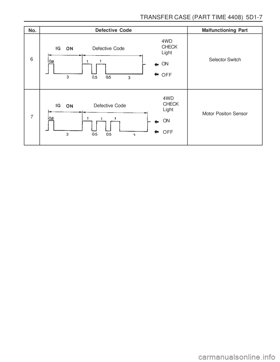
No. Defective Code
Malfunctioning Part
1
2 3 4
5 TCCU
Shift Motor
Synchronizer Clutch
Speed SensorHub Solenoid
4WD CHECK Light ON OFF
Defective Code
4WD CHECK Light ON OFF
Defective Code
4WD CHECKLight ONOFF
Defective Code
4WD CHECKLight ONOFF
Defective Code
4WD CHECK Light ONOFF
Defective Code
Page 1059 of 1574

TRANSFER CASE (PART TIME 4408) 5D1-7
No.Defective Code
Malfunctioning Part
6
7
Selector Switch
Motor Positon Sensor
4WD CHECKLight ONOFF
Defective Code
4WD CHECK Light ON OFF
Defective Code
Page 1082 of 1574

5D1-30 TRANSFER CASE (PART TIME 4408)
Oil Pump
1. Install the pump front cover to be the ‘TOP ’ mark down and
turn the cover to be the ‘TOP ’ mark up when installed in
vehicle.
2. Install the 2 pump pins and spring to the output shaft. NoticeFlat surface of the pins must point out and align the center
line of pins and spring.
3. Connect the hose coupling to the strainer coupling and install the strainer foot into the transfer case slot. Notice
The hose coupling must face the pump assembly.
4. Install the pump housing to be the 'REAR' mark up and seat the 2 pump pins inside of the pump housing by moving pump pins inward and compressing the spring.
5. Tighten the hose to pump housing by hose clamp.
6. Position the pump rear cover to be the ‘TOP REAR ’ mark
up and located at the top of transfer case when installed in
vehicle. Position the pump retainer on the cover so that tab
on the retainer is in notch in the transfer case. Apply Loctite
to the bolts and tighten the bolts with turning the output
shaft by hand to make the pump pins move freely. 45 Shaft and Pump Assembly
46 Bolt
47 Pump Retainer
48 Rear Pump Cover
49 Hose Clamp
50 Hose Coupling
54 Pump Housing
52 Pump Pin
53 Spring
54 Front Pump Cover
55 Output Shaft
56 Strainer
40 Snap Ring
41 Spacer
42 Drive Sprocket
43 Driven Sprocket
44 Drive Chain
55 Output Shaft (Rear)
71 Output Shaft (Front)
Drive Chain
1. Position the drive sprocket to the rear output shaft end and
driven sprocket to the front output shaft end.
2. Install the drive chain onto the sprocket.
3. Holding each sprocket to be the drive chain tight and parallel with transfer case, install the drive chain assembly to the output shafts.
4. Rotate the driven sprocket slightly to engage splines on the front output shaft.
5. Install the spacer to the front output shaft and insert the snap ring into the shaft groove over spacer.
Tightening Torque 4 - 8.5 Nm
Page 1083 of 1574

TRANSFER CASE (PART TIME 4408) 5D1-31
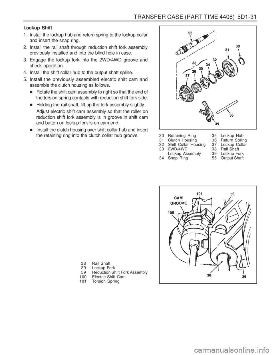
Lockup Shift
1. Install the lockup hub and return spring to the lockup collarand insert the snap ring.
2. Install the rail shaft through reduction shift fork assembly previously installed and into the blind hole in case.
3. Engage the lockup fork into the 2WD/4WD groove and check operation.
4. Install the shift collar hub to the output shaft spline.
5. Install the previously assembled electric shift cam and assemble the clutch housing as follows.
� Rotate the shift cam assembly to right so that the end of
the torsion spring contacts with reduction shift fork side.
� Holding the rail shaft, lift up the fork assembly slightly. Adjust electric shift cam assembly so that the roller on
reduction shift fork assembly is in groove in shift cam and button on lockup fork is on cam end.
� Install the clutch housing over shift collar hub and insert
the retaining ring into the clutch collar hub groove. 30 Retaining Ring
31 Clutch Housing
32 Shift Collar Housing
33 2WD/4WD
Lockup Assembly
34 Snap Ring
38 Rail Shaft
39 Lockup Fork
59 Reduction Shift Fork Assembly
100 Electric Shift Cam
101 Torsion Spring 35 Lockup Hub
36 Return Spring
37 Lockup Collar
38 Rail Shaft
39 Lockup Fork
55 Output Shaft
Page 1088 of 1574

5D1-36 TRANSFER CASE (PART TIME 4408)
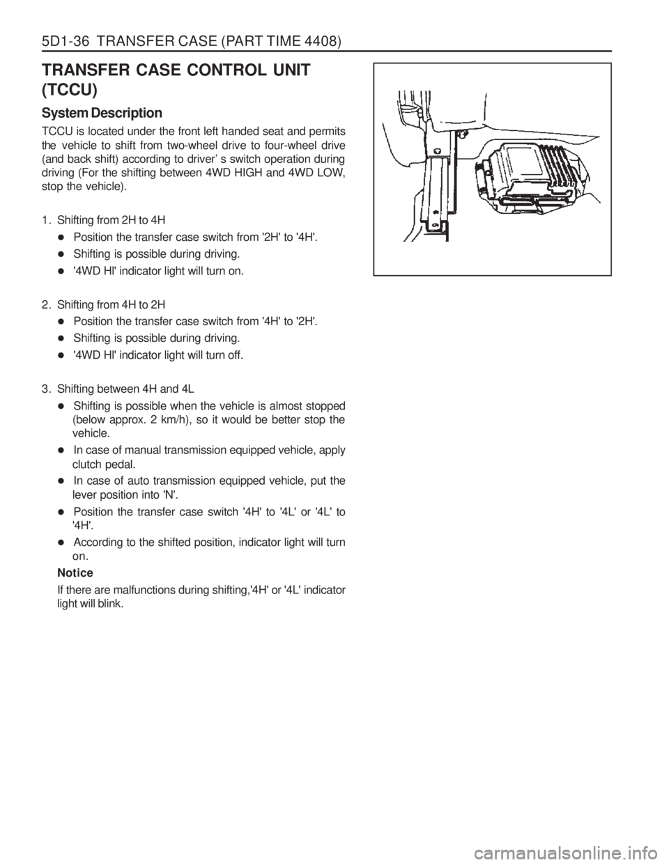
TRANSFER CASE CONTROL UNIT (TCCU) System Description TCCU is located under the front left handed seat and permits the vehicle to shift from two-wheel drive to four-wheel drive
(and back shift) according to driver ’s switch operation during
driving (For the shifting between 4WD HIGH and 4WD LOW, stop the vehicle).
1. Shifting from 2H to 4H
� Position the transfer case switch from '2H' to '4H'.
� Shifting is possible during driving.
� '4WD Hl' indicator light will turn on.
2. Shifting from 4H to 2H � Position the transfer case switch from '4H' to '2H'.
� Shifting is possible during driving.
� '4WD Hl' indicator light will turn off.
3. Shifting between 4H and 4L � Shifting is possible when the vehicle is almost stopped
(below approx. 2 km/h), so it would be better stop the vehicle.
� In case of manual transmission equipped vehicle, apply
clutch pedal.
� In case of auto transmission equipped vehicle, put the
lever position into 'N'.
� Position the transfer case switch '4H' to '4L' or '4L' to
'4H'.
� According to the shifted position, indicator light will turn
on.
Notice
If there are malfunctions during shifting,'4H' or '4L' indicator light will blink.
Page 1089 of 1574

TRANSFER CASE (PART TIME 4408) 5D1-37
Inspection and Repair
1. 4H and 4L indicator light inspection� When turn the ignition switch to "ON" position, 4H and
4L indicator light will turn on for 0.6 second and will turn
off immediately.
Notice
If indicator light does not turn on, check bulb, wiring harness and TCCU.
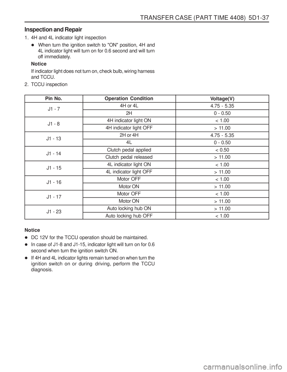
2. TCCU inspection
Pin No. Operation Condition
4H or 4L
2H
4H indicator light ON
4H indicator light OFF 2H or 4H4L
Clutch pedal applied
Clutch pedal released 4L indicator light ON
4L indicator light OFF Motor OFF
Motor ON
Motor OFF Motor ON
Auto locking hub ON
Auto locking hub OFF Voltage(V)
4.75 - 5.35
0 - 0.50< 1.00
> 11.00
4.75 - 5.35 0 - 0.50
< 0.50
> 11.00
< 1.00
> 11.00 < 1.00
> 11.00 < 1.00
> 11.00
> 11.00 < 1.00
J1 - 7
J1 - 8
J1 - 13 J1 - 14 J1 - 15 J1 - 16 J1 - 17 J1 - 23
Notice � DC 12V for the TCCU operation should be maintained.
� In case of J1-8 and J1-15, indicator light will turn on for 0.6
second when turn the ignition switch ON.
� If 4H and 4L indicator lights remain turned on when turn the
ignition switch on or during driving, perform the TCCUdiagnosis.
Page 1141 of 1574

5D2-52 TRANSFER CASE (TOD)
32. Install shift shaft oil seal if it is not installed.
33. Using pliers equipped with soft jaws, rotate the triangularshaft so it is aligned with the triangular slot in the transfer
case shift motor. If triangular shaft will not rotate, rotate the rear output shaft.
34. Slightly loosen the two nuts that attach the slotted support bracket to the end of the motor house.
35. Apply Black Non-Acid Cure Silicone Rubber or equivalent to motor housing base and install on transfer case.
36. Install the transfer case shift motor and three bolts along with speed sensor wire harness bracket and tighten. NoticeThe wire harness must be routed as shown to provide clearance and to prevent the wire harness from grounding
the damper.
37. Holding the slotted support bracket tight against the motor housing end, secure the bracket to the transfer case,
tightening the bolt with lockwasher to 8-11 Nm (72-96 lb-in).
38. Retighten the two nuts that attach the slotted support bracket to the end of the motor.
39. Install the clutch coil wire terminal and sensor wires.