lock SSANGYONG MUSSO 2003 Workshop Manual
[x] Cancel search | Manufacturer: SSANGYONG, Model Year: 2003, Model line: MUSSO, Model: SSANGYONG MUSSO 2003Pages: 1574, PDF Size: 26.41 MB
Page 405 of 1574

1B3-140 OM600 ENGINE MECHANICAL
3. Remove the starter motor and install the engine lock.Engine Lock 602 589 00 40 00
Tools Required 602 589 00 40 00 Engine Lock Removal Procedure
1. Rotate the crankshaft and position the piston of no.1 cylinder
at TDC. Notice Do not rotate the crankshaft in the opposite direction of engine rotation. In this position, the markings of the camshaft/camshaft bearing cap (arrow) must be aligned.
2. Place alignment marks on the camshaft sprocket and timing chain.
Page 407 of 1574

1B3-142 OM600 ENGINE MECHANICAL
4. Install the camshaft bearing caps according to markings(1,2, 3 etc.).
7. Remove the camshaft bearing cap.
8. Pull off the camshaft.
Notice
Be careful not to miss front locking washer.
9. Pull out the locking washer.Notice Check the condition of locking washer and replace if
necessary.
Installation Procedure
1. Insert the locking washer.
2. Check the valve tappet and ensure that tappet moves smoothly.
3. Coat the camshaft with oil and install the camshaft onto the cylinder head so that the TDC marking (arrow) is positioned
upward vertically.
Page 409 of 1574

1B3-144 OM600 ENGINE MECHANICAL
10. Check the TDC marking of OT on the crankshaft.8. Install the chain tensioner.
Tightening Torque 80 Nm
Notice Replace the seal.Before installation, by pumping in the oil approx. 10 times, fill the oil.
9. Remove the engine lock.
Notice If max. length ‘L’ of the 12-sided bolt exceeds 53.6mm,
replace it.
Page 430 of 1574

1B3-166 OM600 ENGINE MECHANICAL Installation Procedure
1. Fit the piston onto the connecting rod so that the arrow(15) and the locking slot (16) are facing in direction of the vehicle.
2. Coat the piston pin (15) with engine oil and insert it by hand. Notice Do not heat up the piston.
3. Install the new snap ring (4) into the grooves (arrow).
4. Check the piston rings (1, 2, 3) and replace them if necessary.
5. Install and arrange the piston rings to be evenly 120 ° from
each ends gap.
Page 452 of 1574

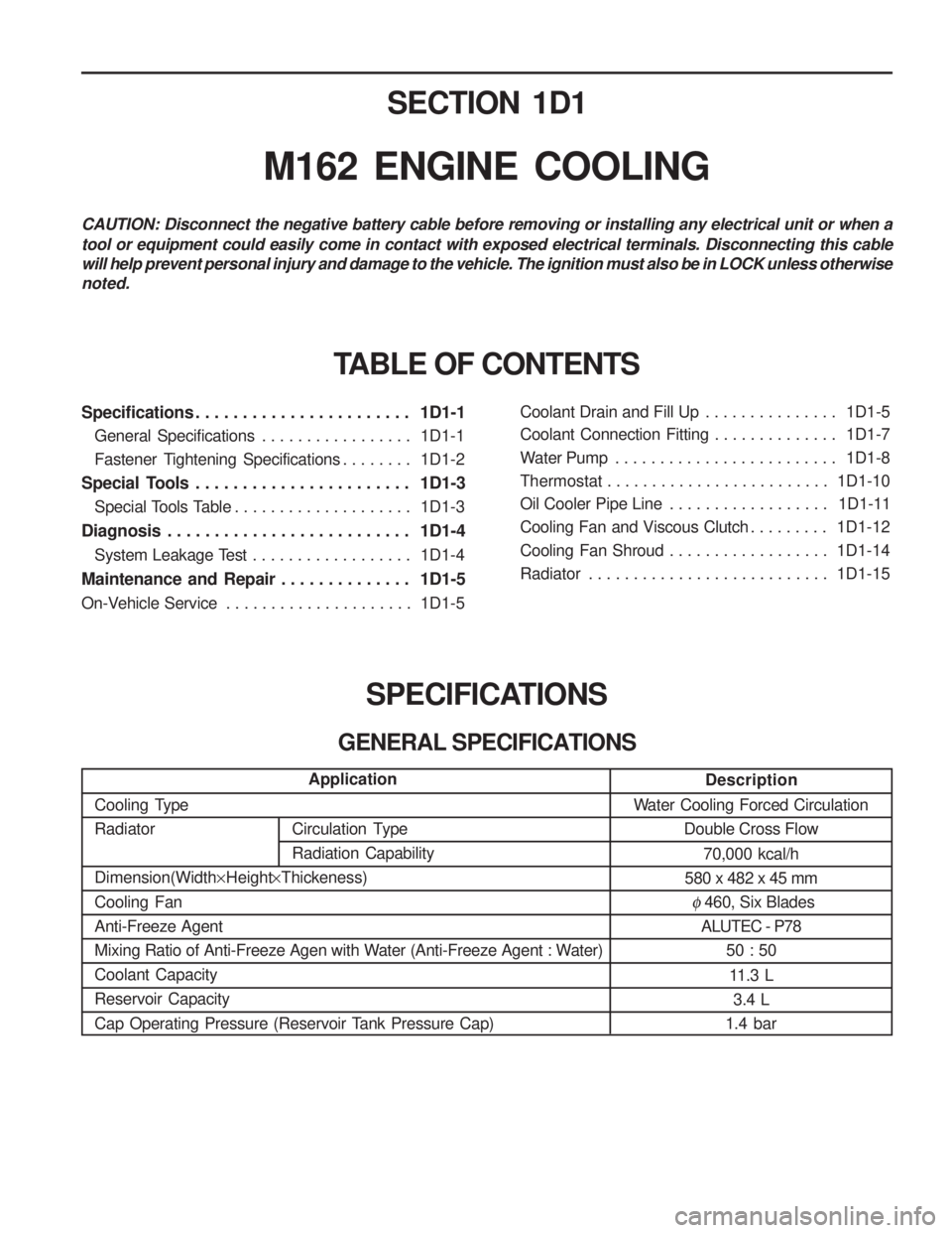
SECTION 1D1
M162 ENGINE COOLING
Specifications . . . . . . . . . . . . . . . . . . . . . . . 1D1-1General Specifications . . . . . . . . . . . . . . . . . 1D1-1
Fastener Tightening Specifications . . . . . . . . 1D1-2
Special Tools . . . . . . . . . . . . . . . . . . . . . . . 1D1-3 Special Tools Table . . . . . . . . . . . . . . . . . . . . 1D1-3
Diagnosis . . . . . . . . . . . . . . . . . . . . . . . . . . 1D1-4 System Leakage Test . . . . . . . . . . . . . . . . . . 1D1-4
Maintenance and Repair . . . . . . . . . . . . . . 1D1-5
On-Vehicle Service . . . . . . . . . . . . . . . . . . . . . 1D1-5Coolant Drain and Fill Up . . . . . . . . . . . . . . .
1D1-5
Coolant Connection Fitting . . . . . . . . . . . . . . 1D1-7
Water Pump . . . . . . . . . . . . . . . . . . . . . . . . . 1D1-8
Thermostat . . . . . . . . . . . . . . . . . . . . . . . . . 1D1-10
Oil Cooler Pipe Line . . . . . . . . . . . . . . . . . . 1D1-11
Cooling Fan and Viscous Clutch . . . . . . . . . 1D1-12
Cooling Fan Shroud . . . . . . . . . . . . . . . . . . 1D1-14
Radiator . . . . . . . . . . . . . . . . . . . . . . . . . . . 1D1-15
SPECIFICATIONS
GENERAL SPECIFICATIONS
CAUTION: Disconnect the negative battery cable before removing or installing any electrical unit or when a tool or equipment could easily come in contact with exposed electrical terminals. Disconnecting this cable will help prevent personal injury and damage to the vehicle. The ignition must also be in LOCK unless otherwisenoted.
TABLE OF CONTENTS
Description
Water Cooling Forced Circulation Double Cross Flow
70,000 kcal/h
580 x 482 x 45 mm
� 460, Six Blades
ALUTEC - P78
50 : 50
11.3 L 3.4 L
1.4 bar
Application
Cooling Type Radiator Dimension(Width ×Height ×Thickeness)
Cooling Fan Anti-Freeze Agent
Mixing Ratio of Anti-Freeze Agen with Water (Anti-Freeze Agent : Water)Coolant CapacityReservoir Capacity
Cap Operating Pressure (Reservoir Tank Pressure Cap)
Circulation Type Radiation Capability
Page 468 of 1574

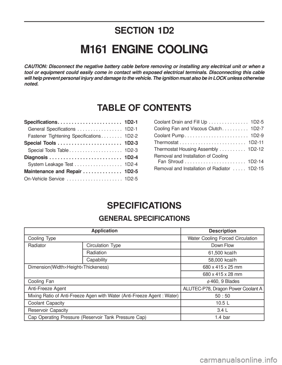
Circulation Type RadiationCapabilitySECTION 1D2
M161 ENGINE COOLING
Specifications . . . . . . . . . . . . . . . . . . . . . . . 1D2-1
General Specifications . . . . . . . . . . . . . . . . . 1D2-1
Fastener Tightening Specifications . . . . . . . . 1D2-2
Special Tools . . . . . . . . . . . . . . . . . . . . . . . 1D2-3
Special Tools Table . . . . . . . . . . . . . . . . . . . . 1D2-3
Diagnosis . . . . . . . . . . . . . . . . . . . . . . . . . . 1D2-4 System Leakage Test . . . . . . . . . . . . . . . . . . 1D2-4
Maintenance and Repair . . . . . . . . . . . . . . 1D2-5
On-Vehicle Service . . . . . . . . . . . . . . . . . . . . . 1D2-5Coolant Drain and Fill Up . . . . . . . . . . . . . . .
1D2-5
Cooling Fan and Viscous Clutch . . . . . . . . . . 1D2-7
Coolant Pump . . . . . . . . . . . . . . . . . . . . . . . . 1D2-9
Thermostat . . . . . . . . . . . . . . . . . . . . . . . . . 1D2-11
Thermostat Housing Assembly . . . . . . . . . . 1D2-12
Removal and Installation of Cooling Fan Shroud . . . . . . . . . . . . . . . . . . . . . . . 1D2-14
Removal and Installation of Radiator . . . . . 1D2-15
SPECIFICATIONS
GENERAL SPECIFICATIONS
CAUTION: Disconnect the negative battery cable before removing or installing any electrical unit or when a tool or equipment could easily come in contact with exposed electrical terminals. Disconnecting this cable will help prevent personal injury and damage to the vehicle. The ignition must also be in LOCK unless otherwisenoted.
TABLE OF CONTENTS
Description
Water Cooling Forced Circulation Down Flow
61,500 kcal/h 58,000 kcal/h
680 x 415 x 25 mm680 x 415 x 28 mm
� 460, 9 Blades
ALUTEC-P78, Dragon Power Coolant A 50 : 5010.5 L 3.4 L
1.4 bar
Application
Cooling TypeRadiator Dimension(Width ×Height ×Thickeness)
Cooling Fan Anti-Freeze Agent
Mixing Ratio of Anti-Freeze Agen with Water (Anti-Freeze Agent : Water) Coolant Capacity Reservoir Capacity
Cap Operating Pressure (Reservoir Tank Pressure Cap)
Page 484 of 1574

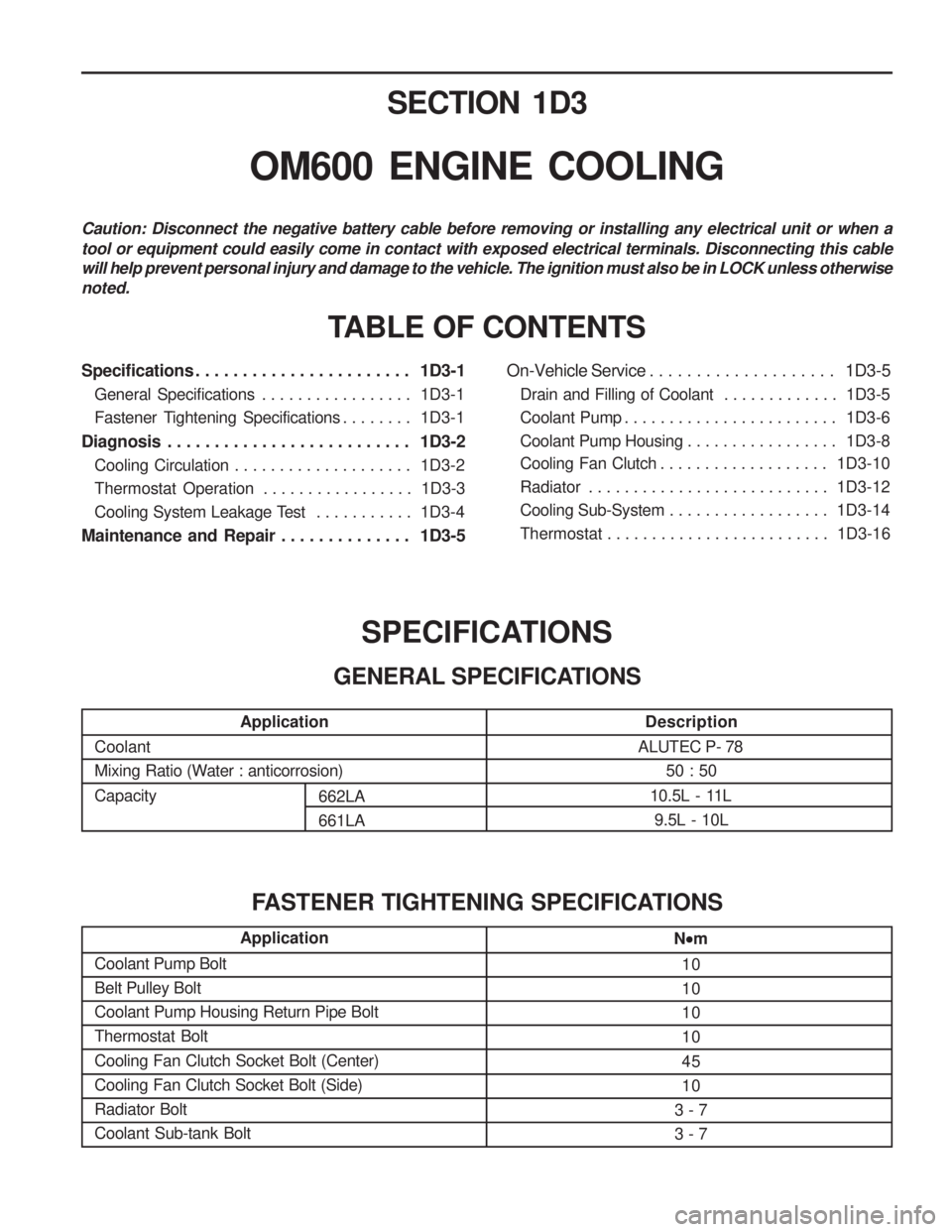
SECTION 1D3
OM600 ENGINE COOLING
Specifications . . . . . . . . . . . . . . . . . . . . . . . 1D3-1General Specifications . . . . . . . . . . . . . . . . . 1D3-1
Fastener Tightening Specifications . . . . . . . . 1D3-1
Diagnosis . . . . . . . . . . . . . . . . . . . . . . . . . . 1D3-2 Cooling Circulation . . . . . . . . . . . . . . . . . . . . 1D3-2
Thermostat Operation . . . . . . . . . . . . . . . . . 1D3-3
Cooling System Leakage Test . . . . . . . . . . . 1D3-4
Maintenance and Repair . . . . . . . . . . . . . . 1D3-5 On-Vehicle Service . . . . . . . . . . . . . . . . . . . .
1D3-5
Drain and Filling of Coolant . . . . . . . . . . . . . 1D3-5
Coolant Pump . . . . . . . . . . . . . . . . . . . . . . . . 1D3-6
Coolant Pump Housing . . . . . . . . . . . . . . . . . 1D3-8
Cooling Fan Clutch . . . . . . . . . . . . . . . . . . . 1D3-10
Radiator . . . . . . . . . . . . . . . . . . . . . . . . . . . 1D3-12
Cooling Sub-System . . . . . . . . . . . . . . . . . . 1D3-14
Thermostat . . . . . . . . . . . . . . . . . . . . . . . . . 1D3-16
TABLE OF CONTENTS
Caution: Disconnect the negative battery cable before removing or installing any electrical unit or when a tool or equipment could easily come in contact with exposed electrical terminals. Disconnecting this cable will help prevent personal injury and damage to the vehicle. The ignition must also be in LOCK unless otherwisenoted.
Application
Coolant
Mixing Ratio (Water : anticorrosion) Capacity
Description
ALUTEC P- 78 50 : 50
10.5L - 11L 9.5L - 10L
SPECIFICATIONS
GENERAL SPECIFICATIONS
Application
Coolant Pump Bolt Belt Pulley BoltCoolant Pump Housing Return Pipe BoltThermostat Bolt Cooling Fan Clutch Socket Bolt (Center) Cooling Fan Clutch Socket Bolt (Side)Radiator BoltCoolant Sub-tank BoltN
m
10 101010 45 10
3 - 73 - 7
FASTENER TIGHTENING SPECIFICATIONS
662LA 661LA
Page 488 of 1574

OM600 ENGINE COOLING 1D3-5
DRAIN AND FILLING OF COOLANT Preceding Work : Removal of skid plate Drain / Filling
1. Loosen the pressure cap of reservoir by 1 notch and removepressure and then loosen the cap. Notice Do not remove radiator cap when coolant is above 90 °C.
2. Open the drain plug and drain the coolant.
Notice Collect the coolant by using the proper bottle.
3. Remove the drain plug(1) and seal(2) of cylinder block and drain the coolant.
4. Replace the seal to new one and tighten the drain plug
Installation Notice
Tightening Torque 30 Nm
5. Tighten the drain plug of the lower radiator.
6. Fill the coolant through coolant reservoir-tank. Notice
� A proportion of 50% by volume of water / anticorrosion
must be ensured
7. After engine is running at idle speed, check the level of coolant. If necessary, add enough specified coolant. MAINTENANCE AND REPAIR
ON-VEHICLE SERVICE
Page 501 of 1574

SECTION 1E1
M162 ENGINE ELECTRICAL
Specifications . . . . . . . . . . . . . . . . . . . . . . . 1E1-1Alternator Specifications . . . . . . . . . . . . . . . . 1E1-1
Starting Motor Specifications . . . . . . . . . . . . 1E1-2
Battery Specifications . . . . . . . . . . . . . . . . . . 1E1-2
Fastener Tightening Specifications . . . . . . . . 1E1-2
Special Tools . . . . . . . . . . . . . . . . . . . . . . . 1E1-3 Special Tools Table . . . . . . . . . . . . . . . . . . . . 1E1-3
Maintenance and Repair . . . . . . . . . . . . . . 1E1-4 On-Vehicle Service . . . . . . . . . . . . . . . . . . . . .
1E1-4
Alternator . . . . . . . . . . . . . . . . . . . . . . . . . . . 1E1-4
Starting Motor . . . . . . . . . . . . . . . . . . . . . . . . 1E1-5
Battery . . . . . . . . . . . . . . . . . . . . . . . . . . . . . 1E1-6
Spark Plug . . . . . . . . . . . . . . . . . . . . . . . . . . 1E1-7
Ignition Cable . . . . . . . . . . . . . . . . . . . . . . . . 1E1-9
Unit Repair . . . . . . . . . . . . . . . . . . . . . . . . 1E1-12 Battery . . . . . . . . . . . . . . . . . . . . . . . . . . . . 1E1-12
SPECIFICATIONS
ALTERNATOR SPECIFICATIONS
CAUTION: Disconnect the negative battery cable before removing or installing any electrical unit or when a tool or equipment could easily come in contact with exposed electrical terminals. Disconnecting this cablewill help prevent personal injury and damage to the vehicle. The ignition must also be in LOCK unless otherwisenoted.
TABLE OF CONTENTS
Application
Output Voltage CurrentResistance Between Rotor Core and Slip Ring Description
12 - 14 V115 A� �
Page 513 of 1574

SECTION 1E2
M161 ENGINE ELECTRICAL
Specifications . . . . . . . . . . . . . . . . . . . . . . . 1E2-1Alternator Specifications . . . . . . . . . . . . . . . . 1E2-1
Starting Motor Specifications . . . . . . . . . . . . 1E2-2
Battery Specifications . . . . . . . . . . . . . . . . . . 1E2-2
Fastener Tightening Specifications . . . . . . . . 1E2-2
Special Tools . . . . . . . . . . . . . . . . . . . . . . . 1E2-3 Special Tools Table . . . . . . . . . . . . . . . . . . . . 1E2-3
Maintenance and Repair . . . . . . . . . . . . . . 1E2-4 On-Vehicle Service . . . . . . . . . . . . . . . . . . . . .
1E2-4
Alternator . . . . . . . . . . . . . . . . . . . . . . . . . . . 1E2-4
Starting Motor . . . . . . . . . . . . . . . . . . . . . . . . 1E2-5
Battery . . . . . . . . . . . . . . . . . . . . . . . . . . . . . 1E2-6
Spark Plug . . . . . . . . . . . . . . . . . . . . . . . . . . 1E2-7
Ignition Cable . . . . . . . . . . . . . . . . . . . . . . . . 1E2-9
Unit Repair . . . . . . . . . . . . . . . . . . . . . . . . 1E2-12 Battery . . . . . . . . . . . . . . . . . . . . . . . . . . . . 1E2-12
CAUTION: Disconnect the negative battery cable before removing or installing any electrical unit or when a tool or equipment could easily come in contact with exposed electrical terminals. Disconnecting this cablewill help prevent personal injury and damage to the vehicle. The ignition must also be in LOCK unless otherwisenoted.
TABLE OF CONTENTS
SPECIFICATIONS
ALTERNATOR SPECIFICATIONS
Application
Output Voltage Current Resistance Between Rotor Core and Slip Ring Description
12 - 14 V115 A
� �