SSANGYONG MUSSO 2003 Service Manual
MUSSO 2003
SSANGYONG
SSANGYONG
https://www.carmanualsonline.info/img/67/57511/w960_57511-0.png
SSANGYONG MUSSO 2003 Service Manual
Trending: wipers, run flat, tailgate, charging, belt, high beam, warning lights
Page 691 of 1574
OM600 ENGINE INTAKE & EXHAUST 1G3-7
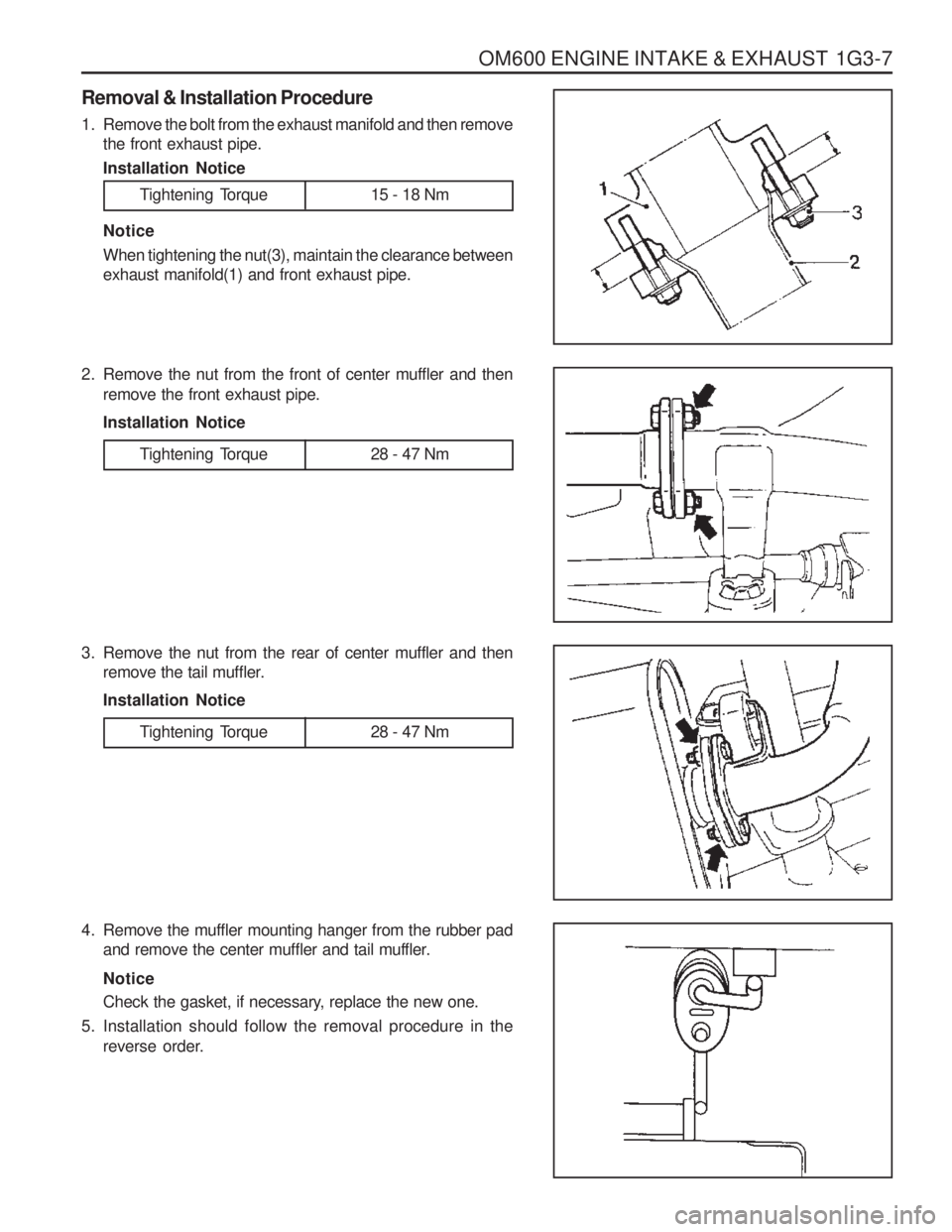
Removal & Installation Procedure
1. Remove the bolt from the exhaust manifold and then removethe front exhaust pipe. Installation Notice
Tightening Torque 15 - 18 Nm
Notice When tightening the nut(3), maintain the clearance between exhaust manifold(1) and front exhaust pipe.
2. Remove the nut from the front of center muffler and then remove the front exhaust pipe. Installation Notice
3. Remove the nut from the rear of center muffler and then remove the tail muffler.Installation Notice
4. Remove the muffler mounting hanger from the rubber pad and remove the center muffler and tail muffler. Notice
Check the gasket, if necessary, replace the new one.
5. Installation should follow the removal procedure in the reverse order.
Tightening Torque 28 - 47 Nm
Tightening Torque 28 - 47 Nm
Page 692 of 1574
1G3-8 OM600 ENGINE INTAKE & EXHAUST
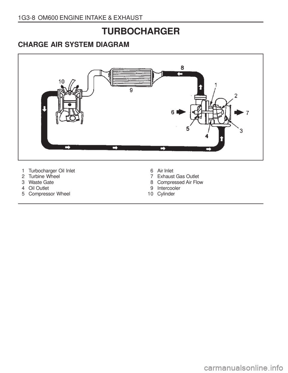
1 Turbocharger Oil Inlet
2 Turbine Wheel
3 Waste Gate
4 Oil Outlet
5 Compressor Wheel6 Air Inlet
7 Exhaust Gas Outlet
8 Compressed Air Flow
9 Intercooler
10 Cylinder
TURBOCHARGER
CHARGE AIR SYSTEM DIAGRAM
Page 693 of 1574
OM600 ENGINE INTAKE & EXHAUST 1G3-9
INTERCOOLER
1 Hoses
2 Pipes
3 Hoses
4 Intercooler5 Cover
6 Bolts
7 Screws
8 Bolts
Page 694 of 1574
1G3-10 OM600 ENGINE INTAKE & EXHAUST
Removal & Installation Procedure
1. Remove the hose connected to turbocharger and intakeduct.
2. Remove the protective cover.
3. Loosen the clamps and remove the pipe and hose connected to intercooler.
4. Unscrew the mounting bolts and remove the intercooler.
5. Installation should follow the removal procedure in the reverse order.
Page 695 of 1574
OM600 ENGINE INTAKE & EXHAUST 1G3-11
TURBOCHARGER ASSEMBLY
1 Oil Supply Line
2 Oil Return Line3 Nuts
4 Turbocharger
Page 696 of 1574
1G3-12 OM600 ENGINE INTAKE & EXHAUST
Removal & Installation Procedure
1. Remove the 2 hoses connected to intercooler.
2. Remove the hose(air cleaner to turbocharger) with blow byhose.
3. Disconnect the oil supply pipe.
4. Remove the oil return pipe.
5. Remove the support assembly.
6. Remove the 3 nuts(arrows).
Page 697 of 1574
OM600 ENGINE INTAKE & EXHAUST 1G3-13
7. Remove the turbocharger disconnecting the exhaust pipefrom the turbocharger.
8. Installation should follow the removal procedure in the reverse order.
Page 698 of 1574

SECTION 2A
SUSPENSION DIAGNOSIS
TABLE OF CONTENTS
Specifications . . . . . . . . . . . . . . . . . . . . . . . . 2A-1
General Specifications . . . . . . . . . . . . . . . . . . 2A-1
Diagnosis . . . . . . . . . . . . . . . . . . . . . . . . . . . 2A-3
General Diagnosis . . . . . . . . . . . . . . . . . . . . . 2A-3
Input & Output Devices and Damping Force Control Logic . . . . . . . . . . . . . . . . . 2A-5
Input & Output Devices . . . . . . . . . . . . . . . . . . 2A-5
System Layout . . . . . . . . . . . . . . . . . . . . . . . . 2A-5Damping Force Control Logic . . . . . . . . . . . . . 2A-6
Normal Control . . . . . . . . . . . . . . . . . . . . . . . . 2A-6
Self-Diagnosis . . . . . . . . . . . . . . . . . . . . . . . . 2A-7
Actuator Inspection . . . . . . . . . . . . . . . . . . . . . 2A-8
Schematic and Routing Diagrams . . . . . . . . 2A-9
ECS Circuit . . . . . . . . . . . . . . . . . . . . . . . . . . . 2A-9
Self Diagnosis Test . . . . . . . . . . . . . . . . . . 2A-12
Diagnosis Test . . . . . . . . . . . . . . . . . . . . . . . 2A-12
SPECIFICATIONS
GENERAL SPECIFICATIONS
188
Application
Front
3-stage Variable Damping Force Control Type Rear
ECS Control Type
344 - 350
Shock Absorber517 - 523
Max. Length (mm)
245 ± 3
Compressed Length (mm) 102
Stroke (mm)331 ± 3
Page 699 of 1574
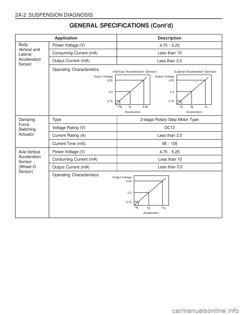
2A-2 SUSPENSION DIAGNOSISApplication
Description
4.75 - 5.25Power Voltage (V)
Axle Vertical Acceleration Sensor(Wheel G Sensor) Less than 10
Consuming Current (mA)
Less than 2.0
Output Current (mA)
Operating Characteristics
Type
Damping Force Switching Actuator3-stage Rotary Step Motor Type
Voltage Rating (V)
DC12
Current Rating (A)
Less than 2.5
Current Time (mS) 95 - 105
4.75 - 5.25Power Voltage (V)
Body
Vertical and Lateral Acceleration Sensor
Less than 10
Consuming Current (mA)
Less than 2.0
Output Current (mA)
Operating Characteristics
Output Voltage
0.752.5
4.25
-1.5g 1g 3.5g
Acceleration
(Vertical Acceleration Sensor)Output Voltage
0.752.5
4.25
-1g 0g 1g
Acceleration
(Lateral Acceleration Sensor)
Output Voltage
0.752.5
4.25
-9g 1g 11g
Acceleration
GENERAL SPECIFICATIONS (Cont'd)
Page 700 of 1574

SUSPENSION DIAGNOSIS 2A-3
DIAGNOSIS
GENERAL DIAGNOSIS
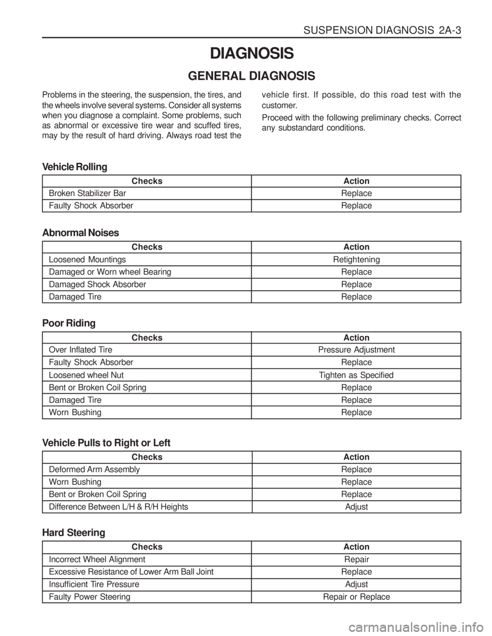
Checks
Loosened Mountings Damaged or Worn wheel BearingDamaged Shock Absorber
Damaged Tire Action
Retightening ReplaceReplaceReplace
Abnormal Noises
Checks
Broken Stabilizer Bar Faulty Shock Absorber Action
ReplaceReplace
Vehicle Rolling
Checks
Over Inflated Tire Faulty Shock Absorber Loosened wheel Nut Bent or Broken Coil Spring
Damaged TireWorn Bushing Action
Pressure Adjustment
Replace
Tighten as Specified ReplaceReplaceReplace
Poor Riding
Problems in the steering, the suspension, the tires, and the wheels involve several systems. Consider all systems when you diagnose a complaint. Some problems, suchas abnormal or excessive tire wear and scuffed tires,may by the result of hard driving. Always road test the
vehicle first. If possible, do this road test with the
customer. Proceed with the following preliminary checks. Correct any substandard conditions.
Checks
Incorrect Wheel Alignment Excessive Resistance of Lower Arm Ball Joint
Insufficient Tire PressureFaulty Power Steering
Action Repair
Replace Adjust
Repair or Replace
Hard Steering
Checks
Deformed Arm Assembly Worn BushingBent or Broken Coil SpringDifference Between L/H & R/H Heights Action
ReplaceReplaceReplace Adjust
Vehicle Pulls to Right or Left
Trending: air conditioning, seat memory, wheel bolt torque, battery, ESP inoperative, lights, tailgate


