engine SSANGYONG MUSSO 2003 Service Manual
[x] Cancel search | Manufacturer: SSANGYONG, Model Year: 2003, Model line: MUSSO, Model: SSANGYONG MUSSO 2003Pages: 1574, PDF Size: 26.41 MB
Page 1318 of 1574

1A-6 MUSSO-SPORTS
SUPPLEMENT
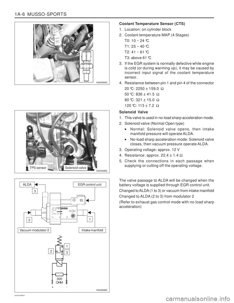
Coolant Temperature Sensor (CTS)
1. Location: on cylinder block
2. Coolant temperature MAP (4 Stages) T0: 10 ~ 24 °C
T1: 25 ~ 40 °C
T2: 41 ~ 61 °C
T3: above 61 °C
3. If the EGR system is normally defective while engine is cold (or during warming up), it may be caused by incorrect input signal of the coolant temperaturesensor.
4. Resistance between pin 1 and pin 4 of the connector 20 °C: 2250 ± 159.0 �
50 °C: 836 ± 41.5 �
80 °C: 321 ± 15.0 �
120 °C: 113 ± 7.2 �
KAA5A040 KAA5A060
KAA5A060Solenoid Valve
1. This valve is used in no-load sharp acceleration mode.
2. Solenoid valve (Normal Open type)
Normal: Solenoid valve opens, then intake
manifold pressure will operate ALDA.
No-load sharp acceleration mode: Solenoid valve
closes, then vacuum pressure operate ALDA.
3. Operating voltage: approx. 12 V
4. Resistance: approx. 22.4 ± 1.4 �
5. Check the connections in each passage when supplying or cutting off the operating voltage.
The valve passage to ALDA will be changed when the battery voltage is supplied through EGR control unit.
Changed to ALDA (1 to 3) or vacuum from intake manifold
Changed to ALDA (2 to 3) from modulator 2 (Refer to exhaust gas control mode with no-load sharp acceleration)
TPS sensorSolenoid valve
Intake manifold
ALDAEGR control unit
3
12
Vacuum modulator 2
2
1
3
300
OHM
+-
Page 1319 of 1574

MUSSO-SPORTS 1A-7
SUPPLEMENT
Throttle Position Sensor (TPS)
1. EGR unit receives TPS signal from TCU (A/T) or input
signal from pin 61 of EGR unit (M/T). The load value of engine is important signal because Huber EGRsystem make EGR valve operate in extended rangeexcept no-load sharp acceleration mode.
2. Resistance check
Disconnect the TPS sensor connector from fuelinjection pump and measure the entire resistancebetween pin 1 and pin 4. Specified value: 5 k � ± 20 %
Measure the resistance between pin 1 and pin 2 at no-load and full-load. Approx. 10 ~ 20 % of full resistance at no-load Approx. 70 ~ 85 % of full resistance at full-load
3. Voltage check
The supplied voltage to TPS from EGR unit (for
M/T) or TCU (for A/T) is approx. 5 V. 0.60 ± 0.2 V at no-load 3.85 ± 0.3 V at full-load
VACUUM LINE Installation of modulator and vacuum line (on-vehicle)
E GR n
Page 1320 of 1574

1A-8 MUSSO-SPORTS
SUPPLEMENT MAINTENANCE AND REPAIR
VACUUM PUMP AND VACUUM LINE This diagnosis procedure checks for vacuum leaks and actuator's operation while performing the actual control of EGR unit through vacuum lines in vacuum pump. The following special service tools should be used for this procedure.
001 589 73 21 00
Manual Vacuum Pump
Multi-Tester 201 589 13 21 00
Vacuum Tester
KAA5A2P0
KAA5A2R0 KAA5A2Q0
VACUUM LINE TEST Check the EGR system when the vehicle produces excessive exhaust gas. Check the vacuum lines for leaks and blocks. If there are not any faults, check the actuators controlled by EGR control unit. Install the tester in position according to the vacuum circuit diagram.
To prevent personal injury, beware of moving parts of engine.
Page 1321 of 1574

MUSSO-SPORTS 1A-9
SUPPLEMENT
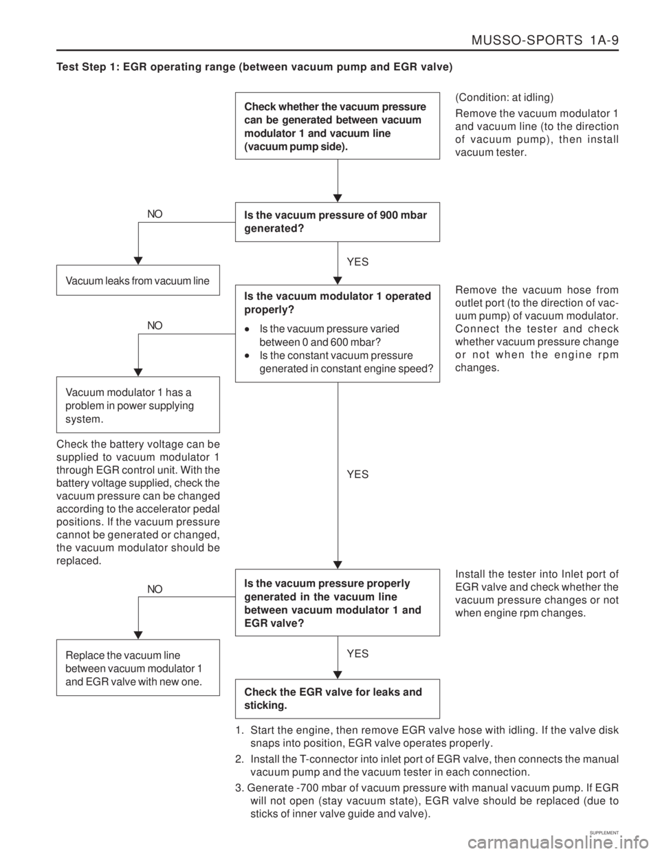
Test Step 1: EGR operating range (between vacuum pump and EGR valve)
(Condition: at idling) Remove the vacuum modulator 1 and vacuum line (to the directionof vacuum pump), then installvacuum tester.
Check whether the vacuum pressure can be generated between vacuum modulator 1 and vacuum line (vacuum pump side).
Is the vacuum pressure of 900 mbar generated?
Is the vacuum pressure properly generated in the vacuum line between vacuum modulator 1 and EGR valve?
Check the EGR valve for leaks and sticking.
Remove the vacuum hose from outlet port (to the direction of vac-uum pump) of vacuum modulator.Connect the tester and checkwhether vacuum pressure changeor not when the engine rpmchanges. Install the tester into Inlet port of EGR valve and check whether thevacuum pressure changes or notwhen engine rpm changes.
1. Start the engine, then remove EGR valve hose with idling. If the valve disk snaps into position, EGR valve operates properly.
2. Install the T-connector into inlet port of EGR valve, then connects the manual vacuum pump and the vacuum tester in each connection.
3. Generate -700 mbar of vacuum pressure with manual vacuum pump. If EGR will not open (stay vacuum state), EGR valve should be replaced (due tosticks of inner valve guide and valve).Vacuum leaks from vacuum line
NO
Is the vacuum modulator 1 operated properly?
Is the vacuum pressure varied
between 0 and 600 mbar?
Is the constant vacuum pressure
generated in constant engine speed?
Check the battery voltage can be supplied to vacuum modulator 1through EGR control unit. With thebattery voltage supplied, check thevacuum pressure can be changedaccording to the accelerator pedalpositions. If the vacuum pressurecannot be generated or changed,the vacuum modulator should bereplaced.
NO
Vacuum modulator 1 has a problem in power supplying system.
NO
Replace the vacuum line between vacuum modulator 1 and EGR valve with new one.
YES YES
YES
Page 1341 of 1574

MUSSO-SPORTS 1A-29
SUPPLEMENT
C101
W/H MAIN
12345 678910
11 12 13 14 15 16 17 18 19 20 21
Main - Engine Main - Engine Engine - MainMain - Floor Floor - FRAME FRAME - DECKMain Engine EngineMain Main Floor
C101 (21Pin, Colorless) C103 (2Pin, White) C108 (16Pin, Black)C206 (Colorless) C904 (10Pin, Black) C905 (12Pin, Black)S101 (Black) G101 G102G201 G204 G301
b. CONNECTOR IDENTIFICATION SYMBOL & PIN NUMBER POSITION
a. CONNECTOR INFORMATION
CONNECTOR(NUMBER)
CONNECTING. WIRING HARNESSCONNECTOR POSITION
Inside The Engine Room Fuse Block Inside The Engine Room Fuse Block Under The Coolant Reservoir Tank Inside Co-Driver Side Cowl PanelBehind The Left FRAME Behind The Left FRAME Inside The Engine Room Fuse BlockBehind The Left Lamp Behind The Right Head Lamp Right The I/P Fuse BlockUpper The ECM Center The Left 'B' Pillar
123 456
HEAD LAMP
MULTI-FUNCTION SWITCH
C1C2
C3 C4
B1 B2 B3 B4
B5 B6 B7 B8 B9
B10
A1 A2 A3 A4 A5 A6
A7 A8 A9
A10 A11 A12 A13 A14
123456789101112
29 30 31 32 33 34 35 36 37 38
28 13 2714261525162417231822
19 2021
39 43 40
44 45 46 4147
48
42
CLUSTER C108
W/H ENGINE
1234 5678
9 101112
13 14 15 16
C103
W/H MAIN
12
5678910 34
HAZARD
SWITCH
2
1
TAIL
LAMP
123 456
1234 5678
9 101112
C905
W/H DECK
5432
109871 6
C904
W/H FLOOR
Page 1343 of 1574

MUSSO-SPORTS 1A-31
SUPPLEMENT
C101
W/H MAIN
12345 678910
11 12 13 14 15 16 17 18 19 20 21
Main - Engine Main - Floor Floor - FRAMMEFRAME - DECK DECK - DECK LID MainEngine Engine MainFloor
C101 (21Pin, Colorless) C206 (Colorless) C904 (10Pin, Black)C905 (12Pin, Black) C906 (2Pin, Black) S101 (Black)G101 G102 G201G301
b. CONNECTOR IDENTIFICATION SYMBOL & PIN NUMBER POSITION
a. CONNECTOR INFORMATION
CONNECTOR(NUMBER)
CONNECTING. WIRING HARNESSCONNECTOR POSITION
Inside The Engine Room Fuse Block Inside Co-Driver Side Cowl Panel Behind The Left FRAME Behind The Left FRAMEBehind The Left DECK LID Inside The Engine Room Fuse Block Behind The Left The LampBehind The Right Head Lamp Right The I/P Fuse Block Center The Left 'B' Pillar
12
TAIL LAMP
LICENCE
LAMP
123 456
HEAD LAMP
MULTI-FUNCTION SWITCH
C1C2
C3 C4
B1 B2 B3 B4
B5 B6 B7 B8 B9
B10
A1 A2 A3 A4 A5 A6
A7 A8 A9
A10 A11 A12 A13 A14
123456789101112
29 30 31 32 33 34 35 36 37 38
28 13 2714261525162417231822
19 2021
39 43 40
44 45 46 4147
48
42
CLUSTER
123 456
C206
W/H MAIN
12 45
78 3
9 10111213 6
14
1234 5678
9 101112
C905
W/H DECK
5432
109871 6
C904
W/H FLOOR
2
1
C906
W/H DECK
Page 1345 of 1574

MUSSO-SPORTS 1A-33
SUPPLEMENT
a. CONNECTOR INFORMATION
b. CONNECTOR IDENTIFICATION SYMBOL & PIN NUMBER POSITION
C351
W/H DRIVER
DOOR
C103
W/H MAIN
C101
W/H MAIN
C361
W/H CO-DRIVER
DOOR TWEETER
12345 678910
11 12 13 14 15 16 17 18 19 20 21
68 9
34
5 2
1
11 7
12 13 14
10
16 1720 21 22 18 19
15
68 9
34
5 2
1
11 7
12 13 14
10
16 1720 21 22 18 19
15
Main - Engine Main - Engine Main - Driver DoorMain - Co-Driver Door Main MainMain
C101 (21Pin, Colorless) C103 (2Pin, White) C351 (22Pin, Blue)C361 (22Pin, White) S201 (Black) S202 (Black)G203 Inside The Engine Room Fuse BlockInside The Engine Room Fuse BlockUpper The I/P Fuse Block Inside Co-Driver Side Cowl Panel Behind The ClusterUnder Right The Audio Right The I/P Fuse Block
CONNECTOR(NUMBER)
CONNECTING. WIRING HARNESSCONNECTOR POSITION
12
1234 5678
9 101112
13 14 15 16
Page 1347 of 1574

MUSSO-SPORTS 1A-35
SUPPLEMENT
Main - Engine Engine - Engine Genertor - EngineMain - T/M Main - T/M MainMain
C103 (2Pin, White) C105 (8Pin, Black) C108 (16Pin, Black)C901 (16Pin, Black) C902 (12Pin, Black) S201 (Black)G204
b. CONNECTOR IDENTIFICATION SYMBOL & PIN NUMBER POSITION
a. CONNECTOR INFORMATION
C902
W/H T/M
C101
W/H MAIN C102
W/H MAIN C108
W/H ENGINE
CONNECTOR(NUMBER) CONNECTING. WIRING HARNESSCONNECTOR POSITION
Inside The Engine Room Fuse Block
Beside Pre-Heating Unit (DSL):MUSSO SPORT
Under The Air Cleaner Housing (DSL, N/Turbo) Upper The T/C(M/T)Upper The T/C(A/T) Behind The Cluster Upper The Huber EGR
1
2
1234
5678
1234 5678
9 101112
13 14 15 16
1234 5678
9 101112
13 14 15 16
C901
W/H T/M
1234
5678
9101112
HUBER EGR
CONTROL UNIT
24
43
23
42
22
41
21
40
20
39
19
38
18
37
17
36
16
35
15
34
14
33
13
32
12
31
11
30
10
29
9
28
8
27
7
26
6
25
62
81
61
80
60
79
59
78
58
77
57
76
56
75
55
74
54
73
53
72
52
71
51
70
50
69
49
68
48
67
47
66
46
65
45
64
12 45 3
44
63
Page 1349 of 1574

1-2 HOW TO USE ELECTRICAL WIRING DIAGRAM
1. HOW TO READ ELECTRICAL WIRING DIAGRAM1) CONTENTS OF ELECTRICAL WIRING DIAGRAM (CIRCUIT)
POSITION EXPLANATION
- Upper horizontal lines : Power supply lines
- Power supply lines : 30, 15, 15A, 15C, 58
- Ef20 or F2 : Fuse Number
• Ef20 : Fuse No #20 in engine room compartment
F2 : Fuse No #2 in passenger room compartment
- Connector (C101~C901) Connector No C203 terminal No1
* Refer to Major Connector Position (Section 2)
- S201 : Splice pack (S101~S306) * Refer to Major Splice Pack Position (Section2)
- Wiring Harness Color * Refer to Wiring Harness Color Abbreviation
- Internal circuit of component (Relay) (Component Name and Terminal Number)
- Internal circuit of component (Switch) (Component Name, Terminal Number and Connecting Wiring Circuit)
- J201 : Joint(J101~J401) * Refer to Major Joint Position(Section2)
- Lower horizontal line : Ground line Ground position(G101~G402)
B : Body Ground
* Refer to Major Ground Position (Section2)
A
B C D E
F
G
H
I
A
B
C
D F
G
E I
H
Page 1350 of 1574

HOW TO USE ELECTRICAL WIRING DIAGRAM 1-3
Connector DiodeFuse in engine room fuse & relay box Fuse in passenger room fuse box Ground Joint - Inline wire connected point Splice pack(Junction connector)
C D
Ef F
G J
S
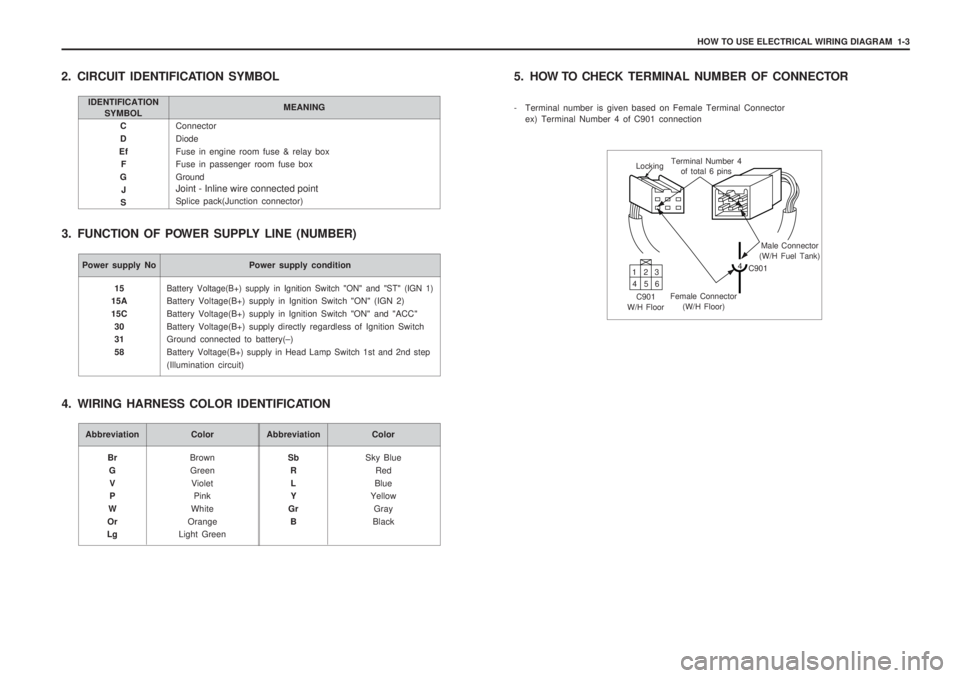
2. CIRCUIT IDENTIFICATION SYMBOL
3. FUNCTION OF POWER SUPPLY LINE (NUMBER)
IDENTIFICATION SYMBOL MEANING
Power supply No Power supply condition
Battery Voltage(B+) supply in Ignition Switch "ON" and "ST" (IGN 1)
Battery Voltage(B+) supply in Ignition Switch "ON" (IGN 2) Battery Voltage(B+) supply in Ignition Switch "ON" and "ACC"Battery Voltage(B+) supply directly regardless of Ignition Switch Ground connected to battery(
–)
Battery Voltage(B+) supply in Head Lamp Switch 1st and 2nd step
(Illumination circuit)
15
15A 15C
30 31 58
Abbreviation Color
BrownGreen Violet Pink
White
Orange
Light Green
Br
GV P
W
Or
LgAbbreviation Color
Sky BlueRed
Blue
Yellow
Gray
Black
Sb
RL Y
Gr B
4. WIRING HARNESS COLOR IDENTIFICATION 5. HOW TO CHECK
TERMINAL NUMBER OF CONNECTOR
- Terminal number is given based on Female Terminal Connector ex) Terminal Number 4 of C901 connection
Locking Terminal Number 4
of total 6 pins
Male Connector
(W/H Fuel Tank)
4 C901
Female Connector (W/H Floor)
C901
W/H Floor 13
2
46 5