Torque SSANGYONG NEW ACTYON SPORTS 2013 Owner's Manual
[x] Cancel search | Manufacturer: SSANGYONG, Model Year: 2013, Model line: NEW ACTYON SPORTS, Model: SSANGYONG NEW ACTYON SPORTS 2013Pages: 751, PDF Size: 72.63 MB
Page 217 of 751
15-170000-00
A fourth correction is made according to the pressure error.
This correction is used to reduce the injection timing advance when the pressure in the rail is higher
than the pressure demand.
A fifth correction is made according to the rate of EGR.
This correction is used to correct the injection timing advance as a function of the rate of exhaust gas
recirculation. -
-
When the EGR rate increases, the injection timing advance must in fact be increased in order to
compensate for the fall in termperature in the cylinder.
A. Main Flow Control
The main flow represents the amount of fuel injected into the cylinder during the main injection. The pilot
flow represents the amount of fuel injected during the pilot injection.
The total fuel injected during 1 cycle (main flow + pilot flow) is determined in the following manner.
When the driver depress the pedal, it is his demand which is taken into account by the system in order
to determine the fuel injected.
When the driver release the pedal, the idle speed controller takes over to determine the minimum fuel
which must be injected into the cylinder to prevent the enigne from stalling. -
-
It is therefore the greater of these 2 values which is retained by the system. This value is then compared
with the lower flow limit determined by the ESP system.
As soon as the injected fuel becomes lower than the flow limit determined by the ESP system, the
antagonistic torque (engine brake) transmitted to the drive wheels exceeds the adherence capacity of
the vehicle and there is therefore a risk of the drive wheels locking.
The system thus chooses the greater of these 2 values (main flow & pilot flow) in order to prevent any
loss of control of the vehicle during a sharp deceleration.
As soon as the injected fuel becomes higher than the fuel limit determined by the ASR trajectory control
system, the engine torque transmitted to the wheels exceeds the adhesion capacity of the vehicle and
there is a risk of the drive wheels skidding. The system therefore chooses the smaller of the two values
in order to avoid any loss of control of the vehicle during accelerations.
The anti-oscillation strategy makes it possible to compensate for fluctuations in engine speed during
transient conditions. This strategy leads to a fuel correction which is added to the total fuel of each
cylinder.
A switch makes it possible to change over from the supercharge fuel to the total fuel according to the
state of the engine.
Until the stating phase has finished, the system uses the supercharged fuel.
Once the engine changes to normal operation, the system uses the total fuel. -
-
(5) Fuel Control
The main fuel is obtained by subtracting the pilot injection fuel from the total fuel.
A mapping determines the minimum fuel which can control an injector as a function of the rail pressure.
As soon as the main fuel falls below this value, the fuel demand changes to 0 because in any case the
injector is not capable of injecting the quantity demand.
Page 219 of 751
15-190000-00
C. Idle Speed Controller
The idle speed controller consists of 2 principal modules:
The first module determines the required idle speed according to:
* The operating conditions of the engine (coolant temperature, gear engaged)
* Any activation of the electrical consumers (power steering, air conditioning, others)
* The battery voltage
* The presence of any faults liable to interface with the rail pressure control or the injection control. In
this case, increase the idle speed to prevent the engine from stalling.
The second module is responsible for providing closed loop control of the engine's idle speed by
adapting the minimum fuel according to the difference between the required idle speed and the
engine speed. -
-
D. Flow Limitation
The flow limitation strategy is based on the following strategies:
The flow limitation depending on the filling of the engine with air is determined according to the
engine speed and the air flow. This limitation allows smoke emissions to be reduced during
stabilized running.
The flow limitation depending on the atmospheric pressure is determined according to the engine
speed and the atmospheric pressure. It allows smoke emissions to be reduced when driving at
altitude.
The full load flow curve is determined according to the gear engaged and the engine speed. It
allows the maximum torque delivered by the engine to be limited.
A performance limitation is introduced if faults liable to upset the rail pressure control or the
injection control are detected by the system. In this case, and depending on the gravity of the fault,
the system activates: -
-
-
-
Reduced fuel logic 1: Guarantees 75 % of the performance without limiting the engine speed.
Reduced fuel logic 2: Guarantees 50 % of the performance with the engine speed limited to
3,000 rpm.
Reduce fuel logic 3: Limits the engine speed to 2,000 rpm.
The system chooses the lowest of all values.
A correction depending on the coolant temperature is added to the flow limitation. This correction makes
it possible to reduce the mechanical stresses while the engine is warming up.
The correction is determined according to the coolant temperature, the engine speed and the time which
has passed since starting.
E. Superchager Flow Demand
The supercharge flow is calculated according to the engine speed and the coolant temperature. A
correction depending on the air temperature and the atmospheric pressure is made in order to increase
the supercharge flow during cold starts. It is possible to alter the supercharge flow value by adding a flow
offset with the aid of the diagnostic tool
Page 239 of 751
15-390000-00
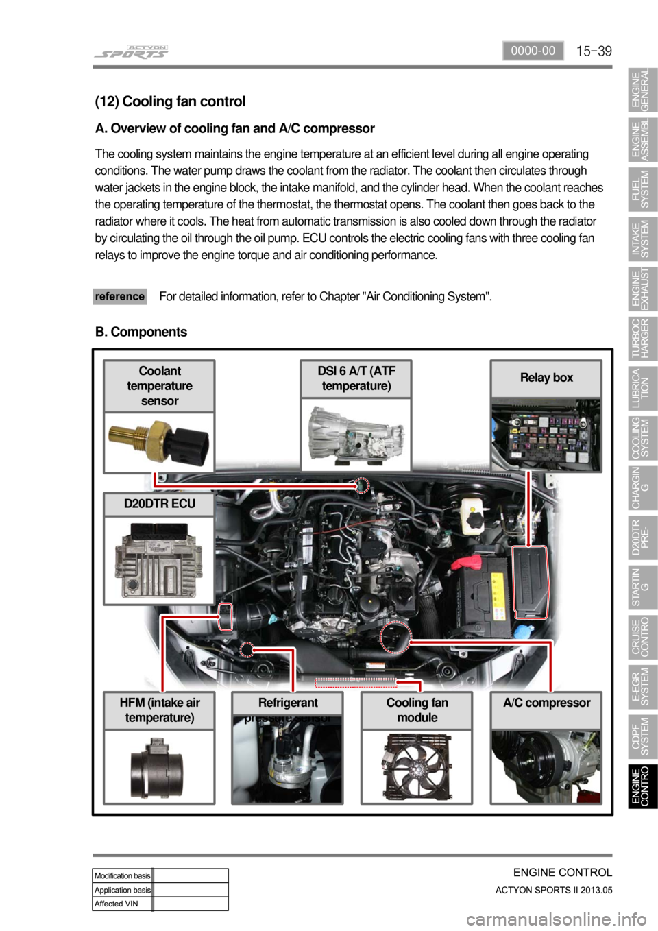
HFM (intake air
temperature)Cooling fan
module
DSI 6 A/T (ATF
temperature)Coolant
temperature
sensor
Refrigerant
pressure sensor
Relay box
(12) Cooling fan control
A. Overview of cooling fan and A/C compressor
The cooling system maintains the engine temperature at an efficient level during all engine operating
conditions. The water pump draws the coolant from the radiator. The coolant then circulates through
water jackets in the engine block, the intake manifold, and the cylinder head. When the coolant reaches
the operating temperature of the thermostat, the thermostat opens. The coolant then goes back to the
radiator where it cools. The heat from automatic transmission is also cooled down through the radiator
by circulating the oil through the oil pump. ECU controls the electric cooling fans with three cooling fan
relays to improve the engine torque and air conditioning performance.
For detailed information, refer to Chapter "Air Conditioning System".
B. Components
A/C compressor
D20DTR ECU
Page 452 of 751

01-6
4WD Automatic Transmission ▶
Torque converter
Oil cooler outletOil cooler return
Inhibiter switch Adapter housing
2) Appearance
Connector plug
Transfer case
Page 453 of 751

01-73680-01
2WD Automatic Transmission ▶
Torque converter
Oil cooler outletOil cooler return
Inhibiter switch Flange for
propeller shaft
Connector plug
Flange for propeller
shaft
Page 454 of 751
01-8
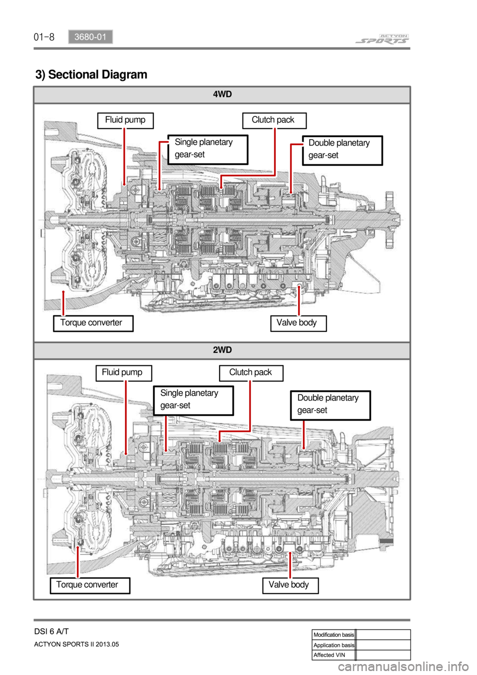
4WD
2WD
3) Sectional Diagram
Fluid pumpClutch pack
Double planetary
gear-set
Torque converter Valve body
Fluid pumpSingle planetary
gear-set
Clutch pack
Torque converter Valve body
Single planetary
gear-setDouble planetary
gear-set
Page 455 of 751

01-93680-01
3. TIGHTENING TORQUE
Description Size x Numbers Tightening torque
Transfer case housing M12 x 32 54 ~ 68
Etension housing M12 x 32 54 ~ 68
Oil pan M6 x 16 4 ~ 6
Valve body to transmission housing M6 x 26 8 ~ 13
Valve body to transmission housing M6 x 45 8 ~ 13
Center support to transmission housing M10 x 34 20 ~ 27
Output shaft locking nut M24 x 15 100 ~ 110
Pump cover to oil pump M8 x 55 24 ~ 27
Pump cover to transmission housing M8 x 40 24 ~ 34
Pump cover to transmission housing M8 x 58 24 ~ 34
Upper valve body to lower valve body M6 x 30 15 ~ 17
Detent spring M8 x 16 20 ~ 25
Variable bleed solenoid and speed sensor
M4 x 12 2.8 ~ 3.2
Transmission oil level plug 30 ~ 35
Front cooling lines to transmission cooler
25 ~ 35
Rear cooling lines to transmission cooler
25 ~ 35
Drive plate to torque converter
40 ~ 42
Gear select lever to shaft rod
14 ~ 20
Page 457 of 751
01-113680-01
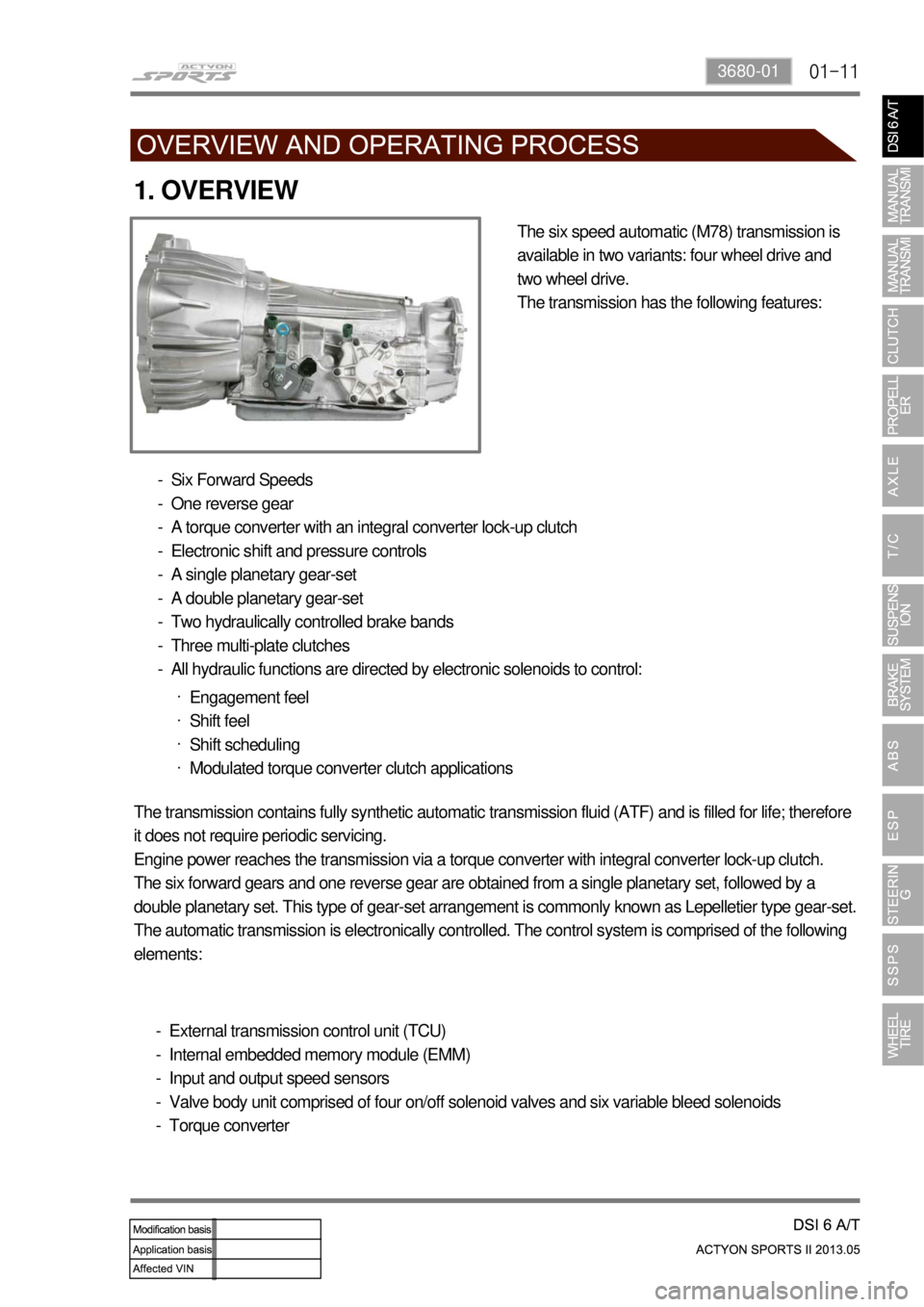
1. OVERVIEW
The six speed automatic (M78) transmission is
available in two variants: four wheel drive and
two wheel drive.
The transmission has the following features:
Six Forward Speeds
One reverse gear
A torque converter with an integral converter lock-up clutch
Electronic shift and pressure controls
A single planetary gear-set
A double planetary gear-set
Two hydraulically controlled brake bands
Three multi-plate clutches
All hydraulic functions are directed by electronic solenoids to control: -
-
-
-
-
-
-
-
-
Engagement feel
Shift feel
Shift scheduling
Modulated torque converter clutch applications ·
·
·
·
The transmission contains fully synthetic automatic transmission fluid (ATF) and is filled for life; therefore
it does not require periodic servicing.
Engine power reaches the transmission via a torque converter with integral converter lock-up clutch.
The six forward gears and one reverse gear are obtained from a single planetary set, followed by a
double planetary set. This type of gear-set arrangement is commonly known as Lepelletier type gear-set.
The automatic transmission is electronically controlled. The control system is comprised of the following
elements:
External transmission control unit (TCU)
Internal embedded memory module (EMM)
Input and output speed sensors
Valve body unit comprised of four on/off solenoid valves and six variable bleed solenoids
Torque converter -
-
-
-
-
Page 458 of 751
01-12
2. FEATURES
Early Downshifts with Hard Braking and Skip Shifts ▶
When heavy braking is detected, the transmission downshifts early and skips gears to provide increased
engine braking to provide gear selection for tip-in.
Gear Hold on Uphill/Downhill ▶
If the accelerator pedal is released when travelling uphill, upshifts are prevented to reduce busyness on
grades. If the accelerator pedal is released when travelling downhill, upshifts are prevented to enhance
engine braking.
Soft Engagement when Shifting to “D” and “R” Position ▶
A soft engagement feature avoids harsh take up of drive when selecting Drive or Reverse. This is
achieved by limiting engine speed and engine torque which results in a rapid, but progressive
engagement of either Drive or Reverse when moving from the Park or Neutral positions. There is no
drive engagement prevention strategy implemented on the transmission system as there is sufficient
engine strategy to protect the system. However, reverse gear engagement is prevented until engine
speed is less than 1400 rpm and the accelerator pedal position is less than 12% and vehicle speed is
less than 10 km/h.
Converter Clutch Lock-Up In All Gears ▶
The transmission features converter clutch lock-up in all gears. This feature provides improved fuel
economy and vehicle performance. It also improves transmission cooling efficiency when towing heavy
loads at low speeds, e.g. in city driving or hill terrain.
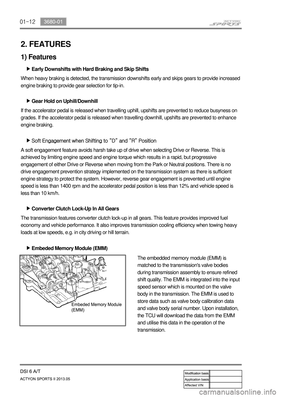
Embeded Memory Module (EMM) ▶
The embedded memory module (EMM) is
matched to the transmission's valve bodies
during transmission assembly to ensure refined
shift quality. The EMM is integrated into the input
speed sensor which is mounted on the valve
body in the transmission. The EMM is used to
store data such as valve body calibration data
and valve body serial number. Upon installation,
the TCU will download the data from the EMM
and utilise this data in the operation of the
transmission.
1) Features
Page 459 of 751

01-133680-01
2) Cooling System
The transmission cooling system ensures rapid warm-up and constant operating temperature resulting
in reduced fuel consumption and refined shift quality.
It also includes a cooler by-pass within the hydraulic system to allow sufficient cooling and lubrication to
the transmission drivetrain in the event of a blockage in the transmission cooler.
Gear Shift ▶
Coastdown ▶
Torque Demand ▶ Transmission gear change is controlled by the TCU. The TCU receives inputs from various engine and
vehicle sensors to select shift schedules and to control the shift feel and torque converter clutch (TCC)
operation at each gear change
Coastdown downshifts occur at 0% accelerator pedal when the vehicle is coasting down to a stop. To
reduce the shift shock and to improve the shift feeling during downshift, TCU electronically controls the
transmission.
Torque demand downshifts occur (automatically) when the driver demand for torque is greater than the
engine can provide at that gear ratio. If applied, the transmission will disengage the TCC to provide
added acceleration.
3) Shift Strategy