SSANGYONG NEW ACTYON SPORTS 2013 Service Manual
NEW ACTYON SPORTS 2013
SSANGYONG
SSANGYONG
https://www.carmanualsonline.info/img/67/57512/w960_57512-0.png
SSANGYONG NEW ACTYON SPORTS 2013 Service Manual
Trending: alternator belt, wiring, instrument cluster, fuse box, AUTO TRANS, sunroof, length
Page 521 of 751
04-53010-01
2. SATIC (SELF ADJUSTING TECHNOLOGY WITH
INTEGRATED CASSETTE)
1) System Description
Function ▶
On the conventional clutch, the pedal force tends
to increase in proportion to the degree of disc
run-out. However, the SATIC clutch has the
adjusting function which activates the cassette
system inserted to the clutch cover to maintain a
constant pedal force and clearance when the
disc runs out. (Unlike SAT type, SATIC type does
not need SST for clutch cover removal.)
Operation ▶
Diaphragm spring rotates the adjusting
equipment as clutch disc is wearing and so,
pressure plate is pushed to clutch disc side at the
amount of wear.
Disc wear (Free
play) → Diaphragm spring (1)
→ Adjusting equipment (2, 3) → Pressure
plate (4)
Page 522 of 751

04-6
2) Overview
Driving elements ▶
The driving elements consist of two flat surfaces machined to a smooth finish.
One of these is the rear face of the engine flywheel and the other is the clutch pressure plate. The clutch
pressure plate is fitted into a clutch steel cover, which is bolted to the flywheel.
Driven elements ▶
The driven element is the clutch disc with a splined hub which is free to slide lengthwise along the splines
of the input shaft.
The driving and driven elements are held in contact by spring pressure. This pressure is exerted by a
diaphragm spring in the clutch cover pressure plate assembly.
Operating Elements ▶
The clutch "release" system consists of the clutch pedal and clutch release cylinder.
This system directly releases the clutch by using hydraulic pressure while the conventional clutch system
releases the clutch by using release lever and release fork. This system provides higher efficiency than
conventional clutch system, and its durability is superior.
Clutch master cylinder (mounted on clutch pedal)
Concentric slave cylinder pipe (mounted inside of transmission) -
-
Page 523 of 751
04-73010-01
3) Layout
Clutch discClutch cover assembly
Dual mass flywheel (DMF)Concentric slave cylinder
Centering pin
Page 524 of 751
04-8
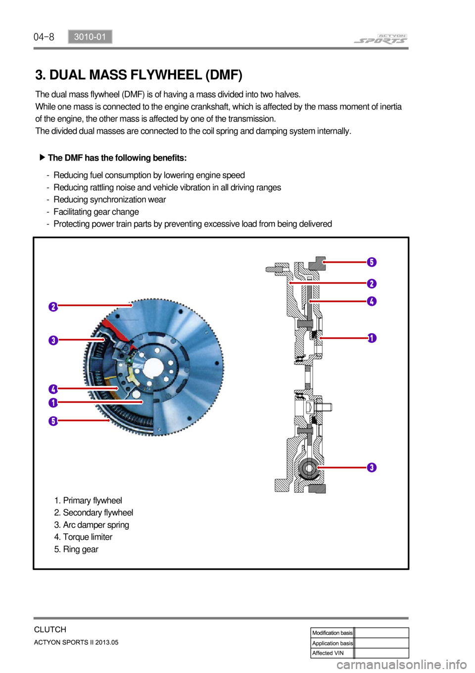
3. DUAL MASS FLYWHEEL (DMF)
The dual mass flywheel (DMF) is of having a mass divided into two halves.
While one mass is connected to the engine crankshaft, which is affected by the mass moment of inertia
of the engine, the other mass is affected by one of the transmission.
The divided dual masses are connected to the coil spring and damping system internally.
The DMF has the following benefits: ▶
Reducing fuel consumption by lowering engine speed
Reducing rattling noise and vehicle vibration in all driving ranges
Reducing synchronization wear
Facilitating gear change
Protecting power train parts by preventing excessive load from being delivered -
-
-
-
-
Primary flywheel
Secondary flywheel
Arc damper spring
Torque limiter
Ring gear 1.
2.
3.
4.
5.
Page 525 of 751
05-33310-00
1. SPECIFICATION
Description Specification
Structure Universal joint with yoke arm and spider
Number of spiders Front Part time T/C Two
Rear Three
Runout Max. 0.3mm
Unbalance Max. 18 g.cm / 4,500 rpm
Dimension of front
propeller shaft (Length x
Dia.) (mm)A/T 552.3*Φ63.5 (Compressed)
M/T 603.8*Φ63.5 (Compressed)
Dimension of front
propeller shaft (Length x
Dia.) (mm)2WD Front1136.0*Φ63.5
Rear743.*Φ63.5(Compressed)
4WD(M/T) Front785.1*Φ63.5
Rear743.*Φ63.5(Compressed)
4WD(A/T) Front836.8*Φ63.5
Rear743.*Φ63.5(Compressed)
2. TIGHTENING TORQUE
Fastener Tightening torque
Mounting bolts for front/rear axle 66.7 ~ 73.5Nm
Mounting bolts for T/M and T/C 79.4 ~ 87.2Nm
Mounting bolts for center bearing 78.4 ~93.1Nm
Page 526 of 751
05-4
1. OVERVIEW
The propeller shaft transfers the power through the transmission and transfer case to the front/rear axle
differential carrier (final reduction gear).
It is manufactured by a thin rounded steel pipe to have the strong resisting force against the torsion and
bending.
Both ends of propeller shaft are connected to the spider and the center of propeller shaft is connected to
the spline to accommodate the changes of the height and length.
The rubber bushing that covers the intermediate bearing keeps the balance of rear propeller shaft and
absorbs its vibration.
Function of propeller shaft ▶
Transmits driving torque.
Compensates the angle change (universal joint / CV joint).
Compensates the axial length change (splines for the slip joint). -
-
-
Front propeller shaft
Rear propeller shaft
Page 527 of 751
06-2
1. SPECIFICATIONS
Location Front Axle Rear Axle
GearType Hypoid←←←
SizeØ182.8 mm ← Ø228.6 mm ←
Offset28.58 mm
(DYMOS)
35 mm(Tongil)←30 mm -
Housing Steel←Steel casting←
OilTypeSAE 80W/90, API
GL-5←SAE 80W/90, API
GL-5←
Capacity 1.4 L←
2.0L
←
Length 448.0 mm←469.0 mm←
Witdh 681.9 mm←1,717.7 mm←
Weight 45 kg←90 kg←
Specification M/T A/T M/T A/T
Gear ratio4.55R(5MT DSL)
4.89R(5MT GSL)3.54(5AT DSL)
3.91(6AT DSL)4.55R(5MT DSL)
4.89R(5MT GSL)3.54(5AT DSL)
3.91(6AT DSL)
Page 528 of 751
07-33240-01
1. SPECIFICATIONS
Description Specifications
Type Part-time transfer case
Total length 343 mm
Mating surface of front flange 40 mm
Weight 32.4 kg (including oil)
Oil capacity 1.4 L
Oil type ATF DEXRON III
Location Transfer case
Major element Housing Part-time & TOD
Bolt 11 ea, M8 x 1.25
Input shaft A/T: outer spline
M/T: inner spline
Page 529 of 751
07-4
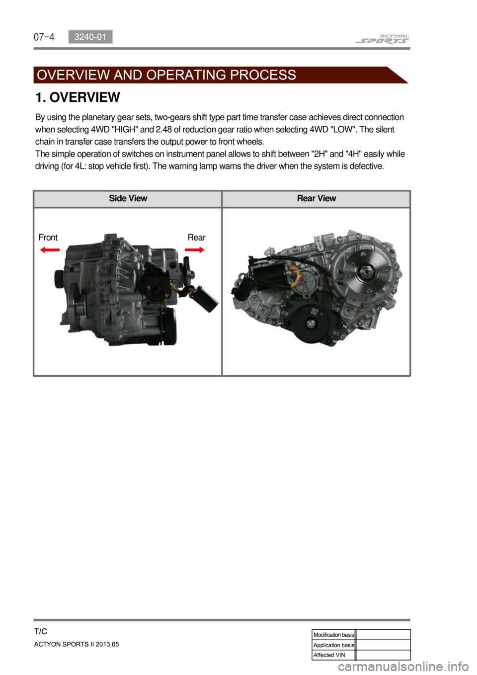
Side View Rear View
1. OVERVIEW
By using the planetary gear sets, two-gears shift type part time transfer case achieves direct connection
when selecting 4WD "HIGH" and 2.48 of reduction gear ratio when selecting 4WD "LOW". The silent
chain in transfer case transfers the output power to front wheels.
The simple operation of switches on instrument panel allows to shift between "2H" and "4H" easily while
driving (for 4L: stop vehicle first). The warning lamp warns the driver when the system is defective.
Front Rear
Page 530 of 751

07-53240-01
Operation ▶
Description Mode Conditions
Driving
mode2H 2 Wheel drive
(rear wheel)Rear-wheel drive mode. This is used under
normal or high-speed driving conditions on
public roads or highways.
4H 4 Wheel drive
(high speed)This is used under sandy, muddy or snow-
covered road conditions
4L 4 Wheel drive
(low speed)This is used for maximum traction.
When cornering with low speed in 4WD
condition, there could be tire dragging, some
mechanical shocks and resistances in
vehicle’s drive train. These are normal
conditions due to internal resistance in the drive
train when the 4WD system is properly working
Mode change2H←4H2 Wheel drive
↔4 Wheel driveShifting is possible while driving at the speed of
70 km/h or less
2H,
4H↔4L2 Wheel drive,
4 Wheel drive (high
speed)
↔4 Wheel drive
(low speed)For Automatic Transmission:
For Manual Transmission:
Stop the vehicle on level ground and
move the gear selector lever into the
“N” position. Turn the switch to the
desired position. ·
Stop the vehicle on level ground and
move the gear selector lever into the
“N” position. Then turn the switch to
the desired position while depressing the
clutch pedal. ·
To make the mode change easily, stop the
vehicle on level ground and turn the mode
switch to the desired position and move the
shift lever to "N"-"R"-"N" while depressing
the brake pedal.
Trending: air conditioning, Torque, mirror controls, parking brake, fuel pressure, tires, load capacity


