wiring SSANGYONG RODIUS 2005 User Guide
[x] Cancel search | Manufacturer: SSANGYONG, Model Year: 2005, Model line: RODIUS, Model: SSANGYONG RODIUS 2005Pages: 502, PDF Size: 70.43 MB
Page 299 of 502

0-12
RODIUS 2005.07
0000-00
ELECTRIC GENERAL
5. WIRING HARNESS ARRANGEMENT
Page 307 of 502

01-9
FUSE AND RELAY
RODIUS 2005.07
8410-05
4. WIRING HARNESS, CONNECTOR & GROUND
LOCATION
1) W/H Engine room
Page 362 of 502

0-10
RODIUS 2005.07
8010-10
CLUSTER
3) Fuel Level Gauge
The fuel level gauge displays the resistance value of the float on the fuel sender in the fuel tank
through a pointer. Note that this vehicle doesn’t have a service hole for checking the fuel
sender connector in the fuel tank.
The fuel sender and its connector can be checked and replaced only when the fuel tank is
removed. The power supply and resistance value should be measured at the connector in front
of the fuel sender (refer to wiring diagram).
When the power supply and output resistance are normal, the float operation by fuel level may
be defective; if so, replace the fuel sender.
Tolerance and resistance value by indicating angle
This table shows the tolerance and resistance value changes by fuel level in normal conditions.
Therefore, the differences that can be occurred by the road conditions and fuel fluctuations are
ignored.
Page 363 of 502

0-11
CLUSTER
RODIUS 2005.07
8010-10
4) Coolant Temperature Gauge
The coolant temperature gauge displays the coolant temperature with a pointer. The angle of
pointer that changes by coolant temperature is as shown below.
Measurement of coolant temperature sensor resistance
Measure the resistance between the terminal and the ground with an ohmmeter and replace i
f
the resistance is out of specified range.
Resistance value by coolant temperature:
20°C : 2449 Ω ±5 %
50°C : 826 Ω ±5 %
80°C : 321 Ω ±5 %
100°C : 112 Ω ±5 %
When the resistance value by coolant temperature is within the specified range, check
thermostat, water pump, radiator related coolant circuit for normal operation. Also, check the
wiring harnesses and connectors for proper connection.
-40 040° °°
Page 419 of 502

0-10
RODIUS 2005.07
6810-20
AIR CONDITIONING SYSTEM
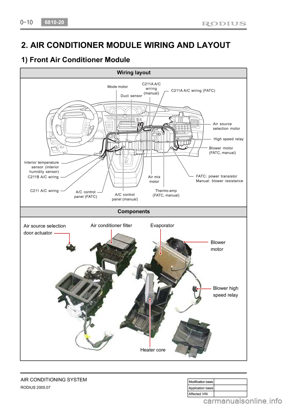
2. AIR CONDITIONER MODULE WIRING AND LAYOUT
1) Front Air Conditioner Module
Wiring layout
Components
Air source selection
door actuatorAir conditioner filterEvaporator
Blower
motor
Blower high
speed relay
Heater core
Page 420 of 502

0-11
AIR CONDITIONING SYSTEM
RODIUS 2005.07
6810-20
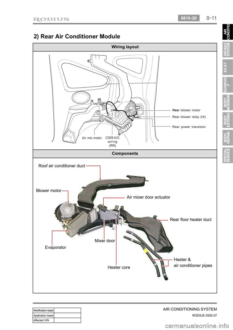
2) Rear Air Conditioner Module
Wiring layout
Components
Roof air conditioner duct
Blower motor
EvaporatorAir mixer door actuator
Rear floor heater duct
Mixer door
Heater coreHeater &
air conditioner pipes
Page 424 of 502

0-15
AIR CONDITIONING SYSTEM
RODIUS 2005.07
6810-20
(3) Inspection
If the active incar sensor defect code (DTC 1) and the humidity sensor defect code (DTC 10)
are set, check as below:
Air conditioner controller
Air conditioner controller connector (based on wiring) AIH sensor (based on sensor)
Active incar sensor
▶
Remove the integrated AIH sensor and measure the resistance between terminal No. 5 and
6 on the sensor connector. (standard: approx. 25°C, 2.2 kΩ)
If the measured value is out of the specified range, replace the AIH sensor. If the measured
values are within the specified range, check as below.
Turn the ignition switch to ON position and measure the voltage to active incar sensor from
the FATC controller connector. (standard: approx. 2 V at 25°C)
If the voltage value cannot be measured, check the circuit for open. If the measured value is
within the specified range, replace the FATC controller.
1.
2.
3.
4.
Page 445 of 502

0-8
RODIUS 2005.07
8810-01
AIR BAG SYSTEM
6) Contact Coil
The contact coil is installed between the steering wheel and the steering column and contains a
coil that enables to contact electrically between the airbag wiring harness, the driver airbag
module and the horn switch.
Turning the steering wheel more than three and onequarter turns may damage the clock
spring. The contact coil should never be disassembled and must be replaced if the airbag
have been deployed. -
Turn the label of the clock spring clockwise to lock and turn the label of the clock spring
counterclockwise approximately 2.9 ± 0.2 turns to the neutral positions with the front
wheels ahead.
Align the pointed marks “43”. -
7) Accelometer Sensor
The accelerometer sensor electronically represents the acceleration or deceleration of the
vehicle during a frontal impact.
In this electronic representation, the electrical signal is proportional to the acceleration o
r
deceleration of the vehicle.
8) Safety Sensor
The safety sensor is safety device made up of a dualcontact, electro-mechanical switch that:
Acts independently of the electronic components.
Connects the acceleration sensor in series in order to make up for the weak points in the
current electronic sensor. 1.
2.
Page 447 of 502

0-10
RODIUS 2005.07
8810-01
AIR BAG SYSTEM
11) Wiring Harness Connectors
If the sensing and diagnostic module (SDM) electrical connector is not attached properly, a built
in shorting bar will connect the wire from airbag warning lamp with the SDM ground wire. This
turns on the AIRBAG indicator.
To prevent deployment during servicing, additional shorting bars are located in following
locations:
Driver airbag module connector
Passenger airbag module connector
Driver and passenger side airbag module connector
SDM wiring harness connector
Contact coil connector to airbag wiring harness ·
·
·
·
·
The shorting bar is only a backup safety device. Always disable the supplemental restraints
system (SRS) before beginning any service procedure.
12) Belt Pretensioner
The belt pretensioner enables to retract the driver and the passenger seat belt webbing to
reduce any personal impact when accounted a frontal collision.
Page 468 of 502

0-21
SEAT
RODIUS 2005.07
7410-01
3) Seat electrical equipment check
Disconnect the seat wiring connector and check if the power is supplied (Refer to the wiring
diagram)
·
1) If the power supply has no problem, remove the seat.
2) Check the motor and wiring if damaged.
3) Connect the battery to the seat connector.
4) Control the seat switch and check the opration.
- Electrical parts are not supplied by a part separately.