engine coolant SSANGYONG RODIUS 2005 Service Manual
[x] Cancel search | Manufacturer: SSANGYONG, Model Year: 2005, Model line: RODIUS, Model: SSANGYONG RODIUS 2005Pages: 502, PDF Size: 70.43 MB
Page 122 of 502
07-6
RODIUS 2005.07
2110-01
ENGINE COOLING SYSTEM
2. DESCRIPTION AND OPERATION
1) GENERAL DESCRIPTION
The cooling system maintains the engine temperature at an efficient level during all engine
operating conditions. When the engine is cold, the cooling system cools the engine slowly o
r
not at all. This slow cooling of the engine allows the engine to warm up quickly.
The cooling system includes a radiator and recovery subsystem, cooling fans, a thermostat and
housing, a water pump, and a water pump drive belt. The timing belt drives the water pump.
All components must function properly for the cooling system to operation. The water pump
draws the coolant from the radiator. The coolant then circulates through water jackets in the
engine block, the intake manifold, and the cylinder head. When the coolant reaches the
operating
temperature of the thermostat, the thermostat opens. The coolant then goes back to the
radiator where it cools.
This system directs some coolant through the hoses to the heat core. This provides for heating
and defrosting. The coolant reservoir is connected to the radiator to recover the coolant
displaced by expansion from the high temperatures. The coolant reservoir maintains the correct
coolant level.
The cooling system for this vehicle has no radiator cap or filler neck. The coolant is added to
the cooling system through the coolant reservoir.
2) RADIATOR
This vehicle has a lightweight tube-and-fin aluminum radiator. Plastic tanks are mounted on the
upper and the lower sides of the radiator core.
On vehicles equipped with automatic transaxles, the transaxle fluid cooler lines run through the
radiator tank. A radiator drain plug is on this radiator.
To drain the cooling system, open the drain plug.
Page 123 of 502
07-7
ENGINE COOLING SYSTEM
RODIUS 2005.07
2110-01
3) COOLANT RESERVOIR
The coolant reservoir is a transparent plastic reservoir, similar to the windshield washer
reservoir.
The coolant reservoir is connected to the radiator by a hose and to the engine cooling system
by another hose. As the vehicle is driven, the engine coolant heats and expands. The portion o
f
the engine coolant displaced by this expansion flows from the radiator and the engine into the
coolant reservoir. The air trapped in the radiator and the engine is degassed into the coolant
reservoir.
When the engine stops, the engine coolant cools and contracts. The displaced engine coolant
is then drawn back into the radiator and the engine. This keeps the radiator filled with the
coolant to the desired level at all times and increases the cooling efficiency.
Maintain the coolant level between the MIN and MAX marks on the coolant reservoir when the
system is cold.
4) THERMOSTAT
A wax pellet-type thermostat controls the flow of the engine coolant through the engine cooling
system. The thermostat is mounted in the thermostat housing to the front of the cylinder head.
The thermostat stops the flow of the engine coolant from the engine to the radiator to provide
faster warm-up, and to regulate the coolant temperature. The thermostat remains closed while
the engine coolant is cold, preventing circulation of the engine coolant through the radiator.
At
this point, the engine coolant is allowed to circulate only throughout the heater core to warm it
quickly and evenly.
As the engine warms, the thermostat opens. This allows the engine coolant to flow through the
radiator where the heat is dissipated. This opening and closing of the thermostat permits
enough engine coolant to enter the radiator to keep the engine within proper engine
temperature operating limits.
The wax pellet in the thermostat is hermetically sealed in a metal case. The wax element of the
thermostat expands when it is heated and contracts when it is cooled.
As the vehicle is driven and the engine warms, the engine coolant temperature increases.
When the engine coolant reaches a specified temperature, the wax pellet element in the
thermostat expands and exerts pressure against the metal case, forcing the valve open. This
allows the engine coolant to flow through the engine cooling system and cool the engine.
As the wax pellet cools, the contraction allows a spring to close the valve.
The thermostat begins to open at 82°C (180°F) and is fully open at 95°C (203°F). The
thermostat closes at 80°C (176°F).
Page 124 of 502
07-8
RODIUS 2005.07
2110-01
ENGINE COOLING SYSTEM
5) WATER PUMP
The belt-driven centrifugal water pump consists of an impeller, a drive shaft, and a belt pulley.
The impeller is supported by a completely sealed bearing.
The water pump is serviced as an assembly and, therefore, cannot be disassembled.
6) ELECTRIC COOLING FAN
Keep hands, tools, and clothing away from the engine cooling fans to help prevent
personal injury. This fan is electric and can turn on even when the engine is not running. -
f a fan blade is bent or damaged in any way, no attempt should be made to repair or reuse
the damaged part.
A bent or damaged fan assembly should always be replaced with a new one to prevent
possible injury. -
The cooling fans are mounted behind the radiator in the engine compartment. The electric
cooling fans increase the flow of air across the radiator fins and across the condenser on ai
r
conditioned (A/C)-equipped vehicles.
This helps to speed cooling when the vehicle is at idle or moving at low speeds.
All models have two fans. The main fan is 320 mm (12.6 inches) in diameter with seven blades
to aid the airflow through the radiator and the condenser. An electric motor attached to the
radiator support drives the fan. The auxiliary fan is 320 mm (12.6 inches) in diameter.
7) A/C OFF OR NON-AC MODEL
The cooling fans are actuated by the engine control module (ECM) using a low-speed
cooling fan relay, a high-speed cooling fan relay and a cooling fan motor relay.
The ECM will turn the cooling fans on at low speed when the coolant temperature reaches
95°C (203°F) and at high speed when the coolant temperature reaches 105°C (221°F).
The ECM will change the cooling fans from high peed to low speed at 100°C (212°F)
and will turn the cooling fans off at 90°C (194°F). ·
·
·
Page 125 of 502

07-9
ENGINE COOLING SYSTEM
RODIUS 2005.07
2110-01
8) A/C ON
The ECM will turn the cooling fans on at low speed when the A/C system is on. The ECM
will change to high speed when the high side A/C pressure reaches 1860 kPa (269.8 psi).
The cooling fans will return to low speed when the high side A/C pressure reaches 1378 kPa
(199.8 psi). ·
·
9) ENGINE COOLANT TEMPERATURE SENSOR
The Engine Coolant Temperature (ECT) sensor uses a temperature to control the signal
voltage to the Engine Control Module (ECM).
10) COOLANT TEMPERATURE GAUGE
The coolant temperature gauge controls the instrument panel temperature indicator. The
coolant temperature gauge is located with ECT sensor.
Page 156 of 502
09-10
RODIUS 2005.07
0452-01
ENGINE CONTROL SYSTEM
1) Starting Mode
When the ignition is turned ON, the ECM turns the fuel pump relay on for 1 second.
The fuel pump then builds fuel pressure.
The ECM also checks the Engine Coolant Temperature (ECT) sensor and the Throttle Position
(TP) sensor and determines the proper air/fuel ratio for starting the engine.
This ranges from1.5 to 1 at -36°C (-33°F) coolant temperature to 14.7 to 1 at 94°C
(201°F) coolant temperature.
The ECM controls the amount of fuel delivered in the starting mode by changing how long the
fuel injector is turned on and off.
This is done by ‘‘pulsing” the fuel injectors for very short times.
<007b008f008c00470099009c0095004700940096008b008c0047008f0088009a0047009b009e00960047008a00960095008b0090009b009000960095009a0047008a008800930093008c008b004702c402c400960097008c00950047009300960096009702
c9004700880095008b004702c402c4008a00930096009a008c>d loop”.
2) Run Mode
3) Open Loop
When the engine is first started and it is above 690 rpm, the system goes into “open
loop” operation. In “open loop”, the ECM ignores the signal from the O2S and calculates
the air/fuel ratio based on inputs from the ECT sensor and the MAF sensor.
The ECM stays in “open loop” until the following conditions are met:
The O2 has a varying voltage output, showing that it is hot enough to operate properly.
<007b008f008c0047006c006a007b0047009a008c0095009a0096009900470090009a0047008800890096009d008c004700880047009a0097008c008a0090008d0090008c008b0047009b008c00940097008c00990088009b009c0099008c0047004f005900
5900550047005c00b6006a00500055>
A specific amount of time has elapsed after starting the engine. -
-
-
4) Closed Loop
The specific values for the above conditions vary with different engines and are stored in the
Electronically Erasable programmable Read-Only Memory (EEPROM).
When these conditions are met, the system goes into “closed loop” operation. In “closed
loop”, the ECM calculates the air/fuel ratio (fuel injector on-time) based on the signals
from the O2 sensors.
This allows the air/fuel ratio to stay very close to 14.7 to 1.
5) Acceleration Mode
The ECM responds to rapid changes in throttle position and airflow and provides extra fuel.
The ECM responds to changes in throttle position and airflow and reduces the amount of fuel.
When deceleration is very fast, the ECM can cut off fuel completely for short periods of time.
6) Deceleration Mode
Page 158 of 502
09-12
RODIUS 2005.07
0452-01
ENGINE CONTROL SYSTEM
Ignition “OFF” ▶
4. INDUCTION SYSTEM
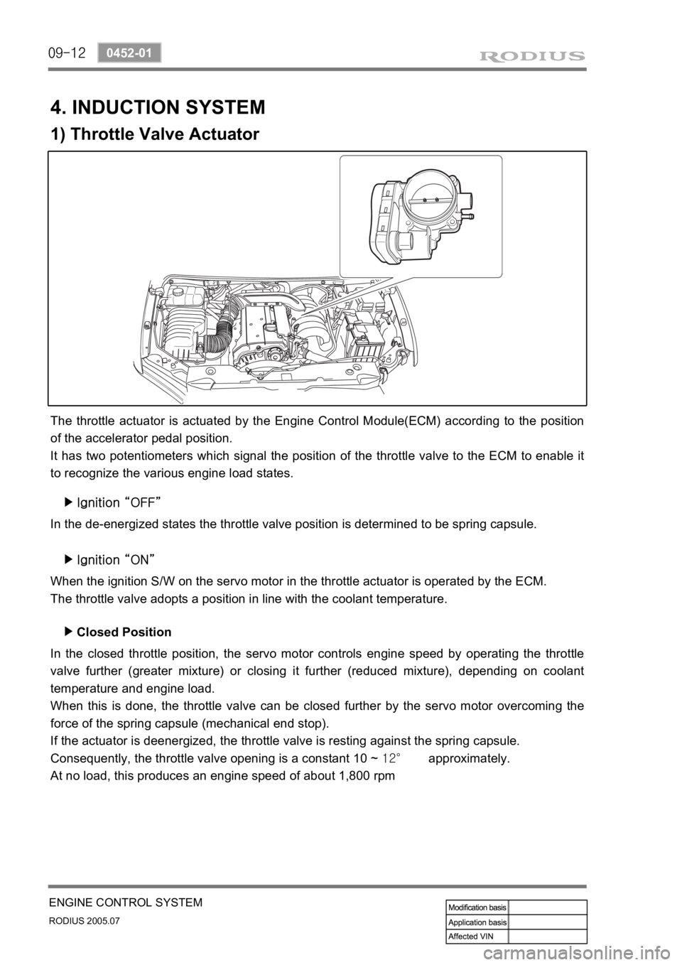
1) Throttle Valve Actuator
The throttle actuator is actuated by the Engine Control Module(ECM) according to the position
of the accelerator pedal position.
It has two potentiometers which signal the position of the throttle valve to the ECM to enable it
to recognize the various engine load states.
In the de-energized states the throttle valve position is determined to be spring capsule.
Ignition “ON” ▶
When the ignition S/W on the servo motor in the throttle actuator is operated by the ECM.
The throttle valve adopts a position in line with the coolant temperature.
In the closed throttle position, the servo motor controls engine speed by operating the throttle
valve further (greater mixture) or closing it further (reduced mixture), depending on coolant
temperature and engine load.
When this is done, the throttle valve can be closed further by the servo motor overcoming the
force of the spring capsule (mechanical end stop).
If the actuator is deenergized, the throttle valve is resting against the spring capsule.
Consequently, the throttle valve opening is a constant 10 ~ 12° approximately.
At no load, this produces an engine speed of about 1,800 rpmClosed Position ▶
Page 415 of 502
0-6
RODIUS 2005.07
6810-20
AIR CONDITIONING SYSTEM
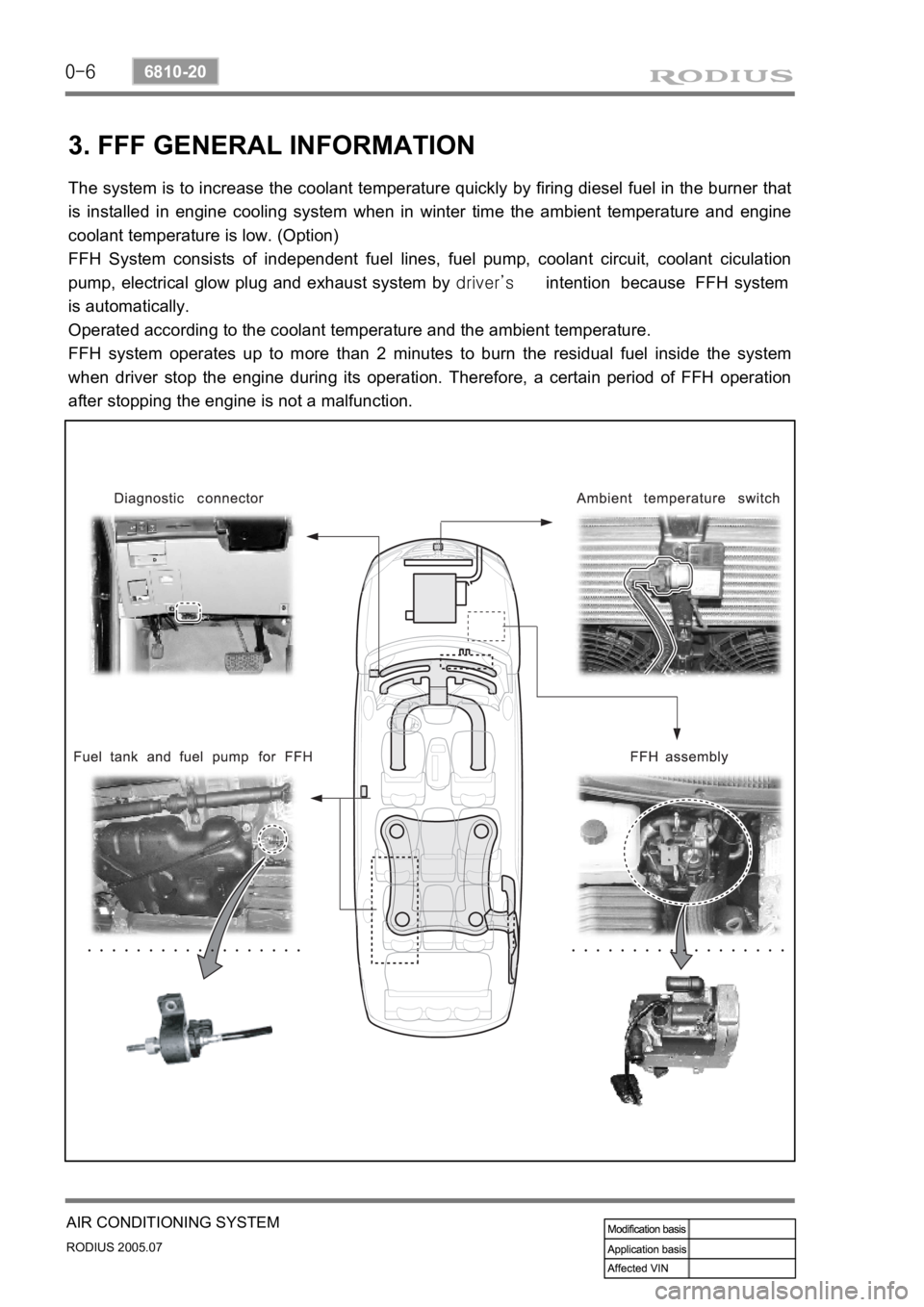
3. FFF GENERAL INFORMATION
The system is to increase the coolant temperature quickly by firing diesel fuel in the burner that
is installed in engine cooling system when in winter time the ambient temperature and engine
coolant temperature is low. (Option)
FFH System consists of independent fuel lines, fuel pump, coolant circuit, coolant ciculation
pump, electrical glow plug and exhaust system by driver’s intention because FFH system
is automatically.
Operated according to the coolant temperature and the ambient temperature.
FFH system operates up to more than 2 minutes to burn the residual fuel inside the system
when driver stop the engine during its operation. Therefore, a certain period of FFH operation
after stopping the engine is not a malfunction.
Page 432 of 502

0-23
AIR CONDITIONING SYSTEM
RODIUS 2005.07
6810-20
3) Mode Door Actuator
The mode door actuator is an actuator that closes, opens and adjusts the mode door for VENT,
FLOOR and DEF mode to change the air flow directions according to FATC controller. Unde
r
the FATC controller AUTO mode, it stays on DEF mode until the engine coolant temperature
reaches at normal operating level and the mode is changed as below when the MODE switch is
pressed.