check engine SSANGYONG RODIUS 2006 Service Manual
[x] Cancel search | Manufacturer: SSANGYONG, Model Year: 2006, Model line: RODIUS, Model: SSANGYONG RODIUS 2006Pages: 444, PDF Size: 56.32 MB
Page 4 of 444
0-4undefined
0000-00
GENERAL INFORMATION3) CIRCUIT IDENTIFICATION SYMBOL
Identification Symbol Meaning
C Connector
D Diode
Ef Fuse in engine room fuse & relay box
F Fuse in passenger room fuse box
G Ground
S Splice pack (Junction connector)
5) WIRING HARNESS COLOR IDENTIFICATION
Abbreviation Color Abbreviation Color
Br Brown Sb Sky Blue
G Green R Red
V Violet L Blue
P Pink Y Yellow
W White Gr Gray
Or Orange B Black
Lg Light Green M Maroon
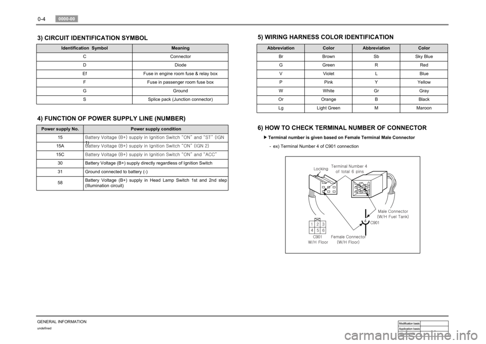
6) HOW TO CHECK TERMINAL NUMBER OF CONNECTOR
Terminal number is given based on Female Terminal Male Connector ▶
ex) Terminal Number 4 of C901 connection -
Power supply No. Power supply condition
15<00690088009b009b008c009900a00047007d00960093009b0088008e008c0047004f0069005200500047009a009c00970097009300a000470090009500470070008e00950090009b0090009600950047007a009e0090009b008a008f004702c80076007502
c9004700880095008b004702c8007a007b02c90047004f0070>GN
1)
15A<00690088009b009b008c009900a00047007d00960093009b0088008e008c0047004f0069005200500047009a009c00970097009300a000470090009500470070008e00950090009b0090009600950047007a009e0090009b008a008f004702c80076007502
c90047004f0070006e0075004700590050>
15C<00690088009b009b008c009900a00047007d00960093009b0088008e008c0047004f0069005200500047009a009c00970097009300a000470090009500470070008e00950090009b0090009600950047007a009e0090009b008a008f004702c80076007502
c9004700880095008b004702c80068006a006a02c9>
30 Battery Voltage (B+) supply directly regardless of Ignition Switch
31 Ground connected to battery (-)
58Battery Voltage (B+) supply in Head Lamp Switch 1st and 2nd step
(Illumination circuit)4) FUNCTION OF POWER SUPPLY LINE (NUMBER)
Page 78 of 444
05-3
ENGINE EXHAUST SYSTEM
RODIUS 2007.07
0000-00
2420-01ENGINE EXHAUST SYSTEM
1. OVERVIEW OF EXHAUST SYSTEM
When you are inspecting or replacing exhaust system components, make sure there is
adequate clearance from all points on the underbody to avoid possible overheating of the
floor panel and possible damage to the passenger compartment insulation and trim
materials.
Check the complete exhaust system and the nearby body areas and trunk lid for broken,
damaged, missing or mispositioned parts, open seams, holes, loose connections, or othe
r
deterioration which could permit exhaust fumes to seep into the trunk may be an indication
of a problem in one of these areas. Any defects should be corrected immediately. -
2. OVERVIEW OF MUFFLER
Aside from the exhaust manifold connection, the exhaust system uses a flange and seal joint
design rather than a slip joint coupling design with clamp and U-bolts.
If hole, open seams, or any deterioration is discovered upon inspection of the front muffler and
pipe assembly, the complete assembly should be replace, the complete assembly should be
replaced.
The same procedure is applicable to the rear muffler assembly. Heat shields for the front and
rear muffler assembly and catalytic converter protect the vehicle and the environment from the
high temperatures that the exhaust system develops.
3. OVERVIEW OF CATALYTIC CONVERTER
When jacking or lifting the vehicle from the body side rails, be certain that the lift pads do
not contact the catalytic converter, as this could damage the catalytic converter. -
Use of anything other than unleaded fuel will damage the catalyst in the catalytic
converter. -
The catalytic converter are emission-control devices added to the exhaust system to
reduce pollutants from the exhaust pipes.
The oxidation catalyst is coated with a catalytic material containing platinum and
palladium, which reduces levels of hydrocarbon (HC) and carbon monoxide (CO) from
the exhaust gas. The three-way catalyst has coatings which contain platinum and
rhodium, which additionally lower the levels of oxides of nitrogen (NOx). ·
·
Page 154 of 444
0-9
CDEF(Catalytic Disel Particulate Filter)
RODIUS 2007.07
0000-00
2) Sytem Composition for Soot Combustion
When the engine is running in low load range, the temperature of exhaust gas is decreased as
the amount of fuel supplied is decreased. To burnt the soot filtered in the CDPF, the control
system should be installed to check the operating range and increase the temperature o
f
exhaust gas by controlling the amount of fuel supplied and and intake air.
Two temperature sensors and one differential pressure sensor monitor the CDPF's operating
range. According to theses sensors' information, the throttle flap decreases the intake ai
r
entered to the throttle body. Also, the fuel injection pattern is added to increase the temperature
of exhaust gas for soot combustion.
There are two fuel injection patterns (pilot injection and main injection). As the CDPF is
installed, the post injection pattern is added.
3) Post Injection and Air Mass Control
When the differential pressure sensor detects the pressure difference between the front and the
rear side of CDPF, the sensor sends signal indicating the soot is acumulated and the post
injection is performed to raise the temperature of exhaust gas. The amount of fuel injected is
determined according to the temperature of exhaust gas detected by the rear temperature
<009a008c0095009a00960099005500470070008d0047009b008f008c0047009b008c00940097008c00990088009b009c0099008c00470090009a00470089008c00930096009e0047005d0057005700b6006a00530047009b008f008c004700880094009600
9c0095009b00470096008d0047008d009c008c009300470090>njected is increased to
<009900880090009a008c0047009b008f008c0047009b008c00940097008c00990088009b009c0099008c005500470070008d0047009b008f008c0047009b008c00940097008c00990088009b009c0099008c00470090009a00470096009d008c0099004700
5d0057005700b6006a00530047009b008f008c004700880094>ount of fuel injected is
decreased or not controlled.
When the engine is running in low load range, the amount of post injection and the amount of
intake air are controlled.
It is to raise the temperature by increasing the amount of fuel while decreasing the amount of
intake air.
Page 157 of 444
0-12
RODIUS 2007.07
0000-00
CDEF(Catalytic Disel Particulate Filter)
6) CDPF Over Load (Notice of Beginning CPF Regeneration Mode
- P1430)
The CDPF system enters the regeneration mode when the mileage is around 600 ~ 1,200
km, depending on the driving condition and driving habits. At this moment, the ECU
performs the CDPF regeneration process; however, the driver may not notice anything
because there is no engine warning or other signals indicating such process.
The control logic in the regeneration process is to increase the exhaust gas temperature by
increasing the fuel injection during post injection process and controlling the intake ai
r
amount(throttle body), and no significant change can be noticed in the vehicle condition.
The engine CHECK lamp flashes but there is no decrease in engine torque.
The engine CHECK lamp flashes to inform the driver when there is an over load due to soot
accumulation because the regeneration temperature cannot be reached due to low speed,
even though CDPF regeneration is in process.
The CDPF regeneration process must be completed by driving for 15-20 minutes at a speed
higher than 80 km/h to solve this problem.
The engine CHECK lamp flashes when CDPF is over loaded; therefore, 4) above must be
performed in this case. 1.
2.
3.
4.
5.
7) CDPF's Excessive Soot Accumulation (P0432)
When the vehicle is driven at a low speed (5-10 km/h) for a long time or long distance, the
soot over accumulates inside the CDPF and the combustion temperature cannot be reached
even by performing the soot combustion process. In this case, this DTC is generated.
This is more serious situation than the CDPF over load condition. Therefore, the engine
power is decreased to protect the system and the engine CHECK lamp is turned on.
Blow the soot between the engine and the exhaust system several times and clear the DTC
to solve this problem. If the same DTC is generated again, check the system according to
the DTC description related to the differential pressure sensor.
* This DTC is actually generated mostly due to the related system malfunction, such as
differential pressure sensor malfunction. 1.
2.
3.
Page 212 of 444
0-39
STICS
RODIUS 2007.07
8710-01
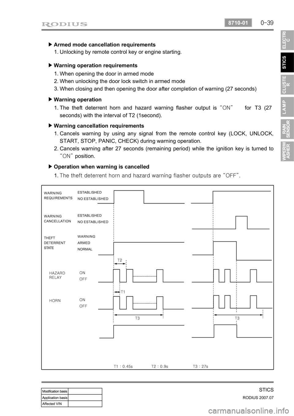
Armed mode cancellation requirements ▶
Unlocking by remote control key or engine starting. 1.
Warning operation requirements ▶
When opening the door in armed mode
When unlocking the door lock switch in armed mode
When closing and then opening the door after completion of warning (27 seconds) 1.
2.
3.
Warning operation ▶
The theft deterrent horn and hazard warning flasher output is “ON” for T3 (27
seconds) with the interval of T2 (1second). 1.
Warning cancellation requirements ▶
Cancels warning by using any signal from the remote control key (LOCK, UNLOCK,
START, STOP, PANIC, CHECK) during warning operation.
Cancels warning after 27 seconds (remaining period) while the ignition key is turned to
“ON” position. 1.
2.
Operation when warning is cancelled ▶
<007b008f008c0047009b008f008c008d009b0047008b008c009b008c00990099008c0095009b0047008f009600990095004700880095008b0047008f008800a100880099008b0047009e00880099009500900095008e0047008d00930088009a008f008c00
9900470096009c009b0097009c009b009a004700880099008c> “OFF”. 1.
Page 216 of 444
0-4
RODIUS 2007.07
8010-10
CLUSTER
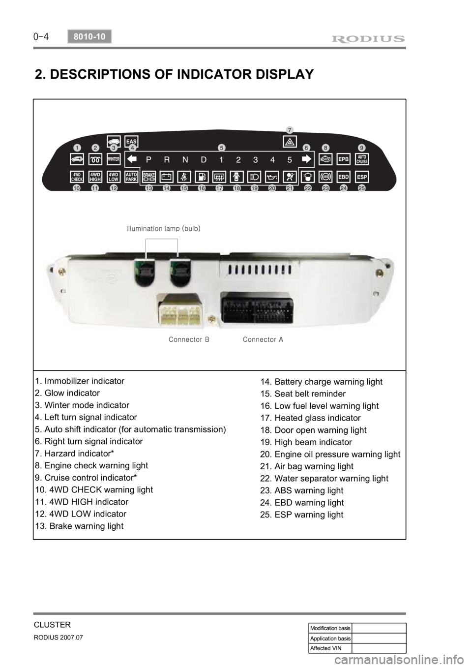
2. DESCRIPTIONS OF INDICATOR DISPLAY
1. Immobilizer indicator
2. Glow indicator
3. Winter mode indicator
4. Left turn signal indicator
5. Auto shift indicator (for automatic transmission)
6. Right turn signal indicator
7. Harzard indicator*
8. Engine check warning light
9. Cruise control indicator*
10. 4WD CHECK warning light
11. 4WD HIGH indicator
12. 4WD LOW indicator
13. Brake warning light14. Battery charge warning light
15. Seat belt reminder
16. Low fuel level warning light
17. Heated glass indicator
18. Door open warning light
19. High beam indicator
20. Engine oil pressure warning light
21. Air bag warning light
22. Water separator warning light
23. ABS warning light
24. EBD warning light
25. ESP warning light
Page 242 of 444
0-7
RAIN SENSOR
RODIUS 2007.07
8610-11
4. FUNCTIONS OF RAIN SENSOR
1) Windshield Glass and Coupler Attachment
Check the outer windshield surface of sensing area for wear, damage and scratch. The sensor
is able to compensate the wear up to a specific level. Check the coupler attached surface of
windshield for porosity. If the porosity exists, the sensor cannot function properly.
2) Recognition of AUTO Mode
3) Instant Wipe Function
When the variable resistance knob on the multifunction wiper switch is turned by each 1 stage
from low sensitivity (Smark) to high sensitivity (F mark), the wiper operates one cycle.
And, the wiper also operates during raining up to 5 minutes after rain stops.When the engine is started with the wiper switch “AUTO” position, the wiper operates
one cycle to remind a driver that the wiper switch is in “AUTO” position.
When the wiper switch is turned to “AUTO” from OFF, the wiper operates one cycle. It
always operates one cycle for the initial operation, however, the wiper does not operate
afterwards to prevent the wiper blade wear if not raining when turning the wiper switch to
“AUTO” from “OFF”. However, the wiper operates up to 5 minutes after rain stops.
If this function does not occur, check No. 2 terminal on the rain sensor. If any defective
cannot be found, check the wiper relay (LOW) for defective. 1)
2)
3)If the installed wiper brushes are out of specification (size and length), the rain sensing
area cannot be fully wiped. In this case, the rain sensor’s sensitivity could be
decreased and the wipers are not properly operated -
As described, the STICS recognizes the wiper switch “AUTO” position. If there are not
any problem, go to diagnosis mode in STICS and check the terminal that receives signal
from wiper and communication lines between rain sensor unit and STICS. -
Page 272 of 444
0-5
CLUTCH
RODIUS 2007.07
3010-01
4) SAT (Self Adjusting Technology)
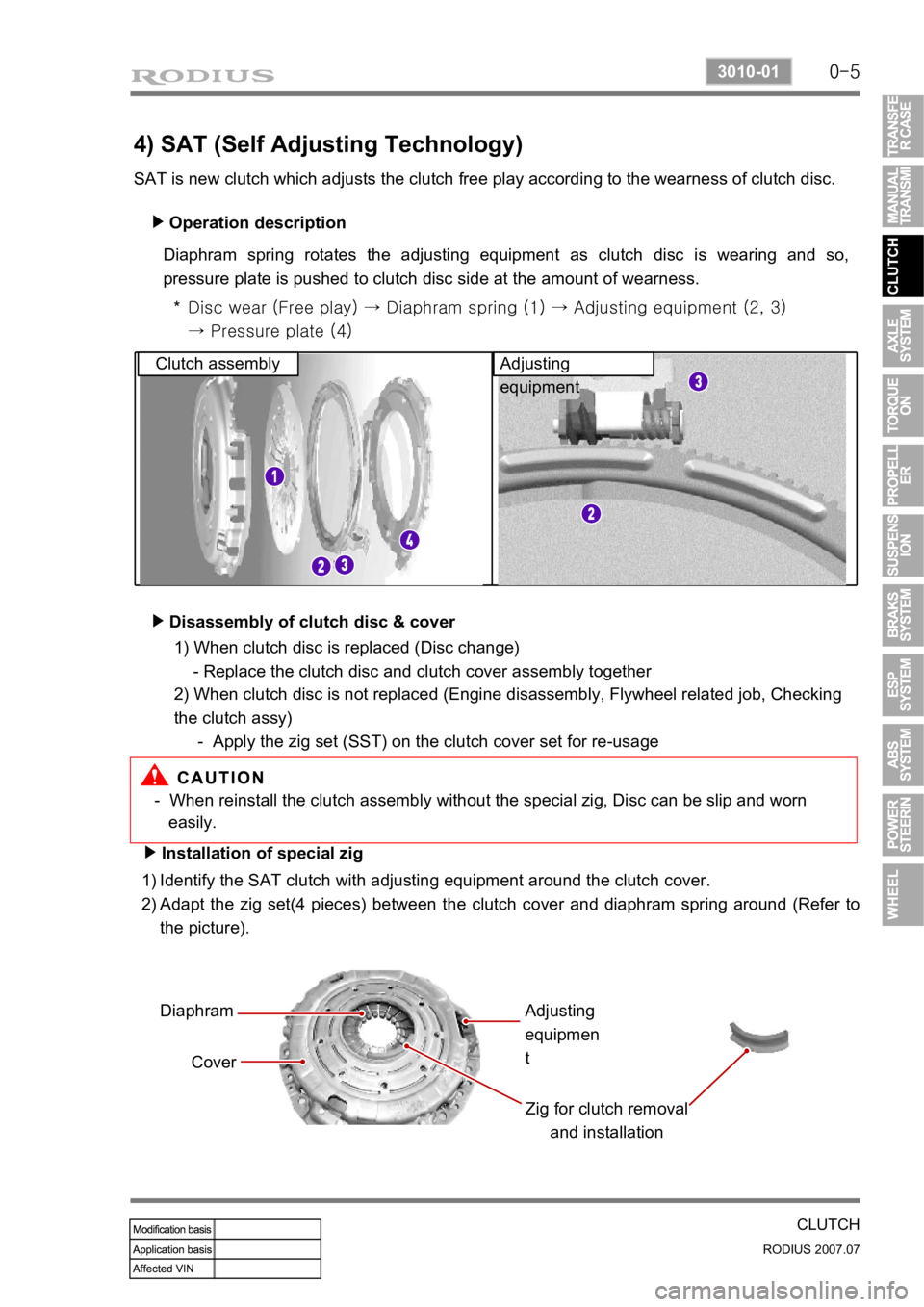
SAT is new clutch which adjusts the clutch free play according to the wearness of clutch disc. Operation description
▶
Diaphram spring rotates the adjusting equipment as clutch disc is wearing and so,
pressure plate is pushed to clutch disc side at the amount of wearness.
Disc wear (Free play) → Diaphram spring (1) → Adjusting equipme nt (2, 3)
→ Pressure plate (4)
*
Clutch assembly Adjusting
equipment
Disassembly of clutch disc & cover
▶
- When reinstall the clutch assembly without the special zig, Disc can be slip and worn
easily.
Installation of special zig
▶
Identify the SAT clutch with adjusting equipment around the clutch cover.
Adapt the zig set(4 pieces) between the clutch cover and diaphram spring around (Refer to
the picture).
1)
2)
Diaphram
Cover Zig for clutch removal and installationAdjusting
equipmen
t
1) When clutch disc is replaced (Disc change)
- Replace the clutch disc and clutch cover assembly together
2) When clutch disc is not replaced (Engine disassembly, Flywheel related job, Checking
the clutch assy)
- Apply the zig set (SST) on the clutch cover set for re-usage
Page 278 of 444
0-5
TORQUE ON DEMAND
RODIUS 2007.07
3240-01
2. GENERAL DESCRIPTION
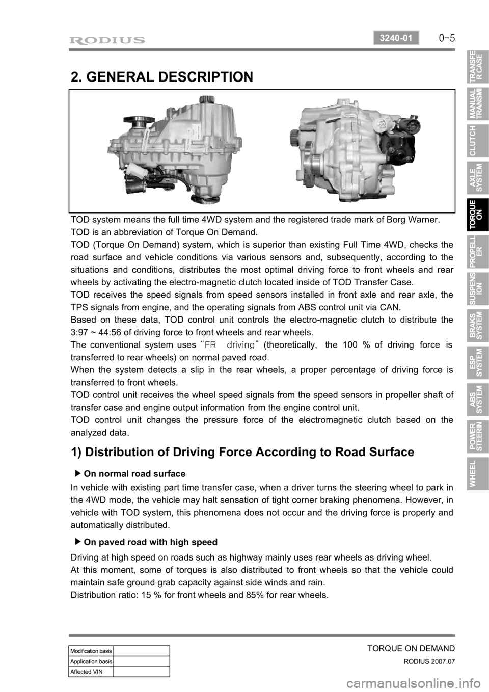
TOD system means the full time 4WD system and the registered trade mark of Borg Warner.
TOD is an abbreviation of Torque On Demand.
TOD (Torque On Demand) system, which is superior than existing Full Time 4WD, checks the
road surface and vehicle conditions via various sensors and, subsequently, according to the
situations and conditions, distributes the most optimal driving force to front wheels and rea
r
wheels by activating the electro-magnetic clutch located inside of TOD Transfer Case.
TOD receives the speed signals from speed sensors installed in front axle and rear axle, the
TPS signals from engine, and the operating signals from ABS control unit via CAN.
Based on these data, TOD control unit controls the electro-magnetic clutch to distribute the
3:97 ~ 44:56 of driving force to front wheels and rear wheels.
The conventional system uses “FR driving” (theoretically, the 100 % of driving force is
transferred to rear wheels) on normal paved road.
When the system detects a slip in the rear wheels, a proper percentage of driving force is
transferred to front wheels.
TOD control unit receives the wheel speed signals from the speed sensors in propeller shaft o
f
transfer case and engine output information from the engine control unit.
TOD control unit changes the pressure force of the electromagnetic clutch based on the
analyzed data.
1) Distribution of Driving Force According to Road Surface
On normal road surface ▶
In vehicle with existing part time transfer case, when a driver turns the steering wheel to park in
the 4WD mode, the vehicle may halt sensation of tight corner braking phenomena. However, in
vehicle with TOD system, this phenomena does not occur and the driving force is properly and
automatically distributed.
On paved road with high speed ▶
Driving at high speed on roads such as highway mainly uses rear wheels as driving wheel.
At this moment, some of torques is also distributed to front wheels so that the vehicle could
maintain safe ground grab capacity against side winds and rain.
Distribution ratio: 15 % for front wheels and 85% for rear wheels.
Page 352 of 444
0-8
RODIUS 2007.07
4710-09
WHEEL
3. WHEEL ALIGNMENT
The first responsibility of engineering is to design safe steering and suspension systems. Each
component must be strong enough to with stand and absorb extreme punishment.
Both the steering system and the front and the rear suspension must function geometrically
with the body mass.
The steering and suspension systems require that the front wheels self-return and that the tire
rolling effort and the road friction be held to a negligible force in order to allow the customer to
direct the vehicle with the least effort and the most comfort.
A complete wheel alignment check should include measurements of the rear toe and camber.
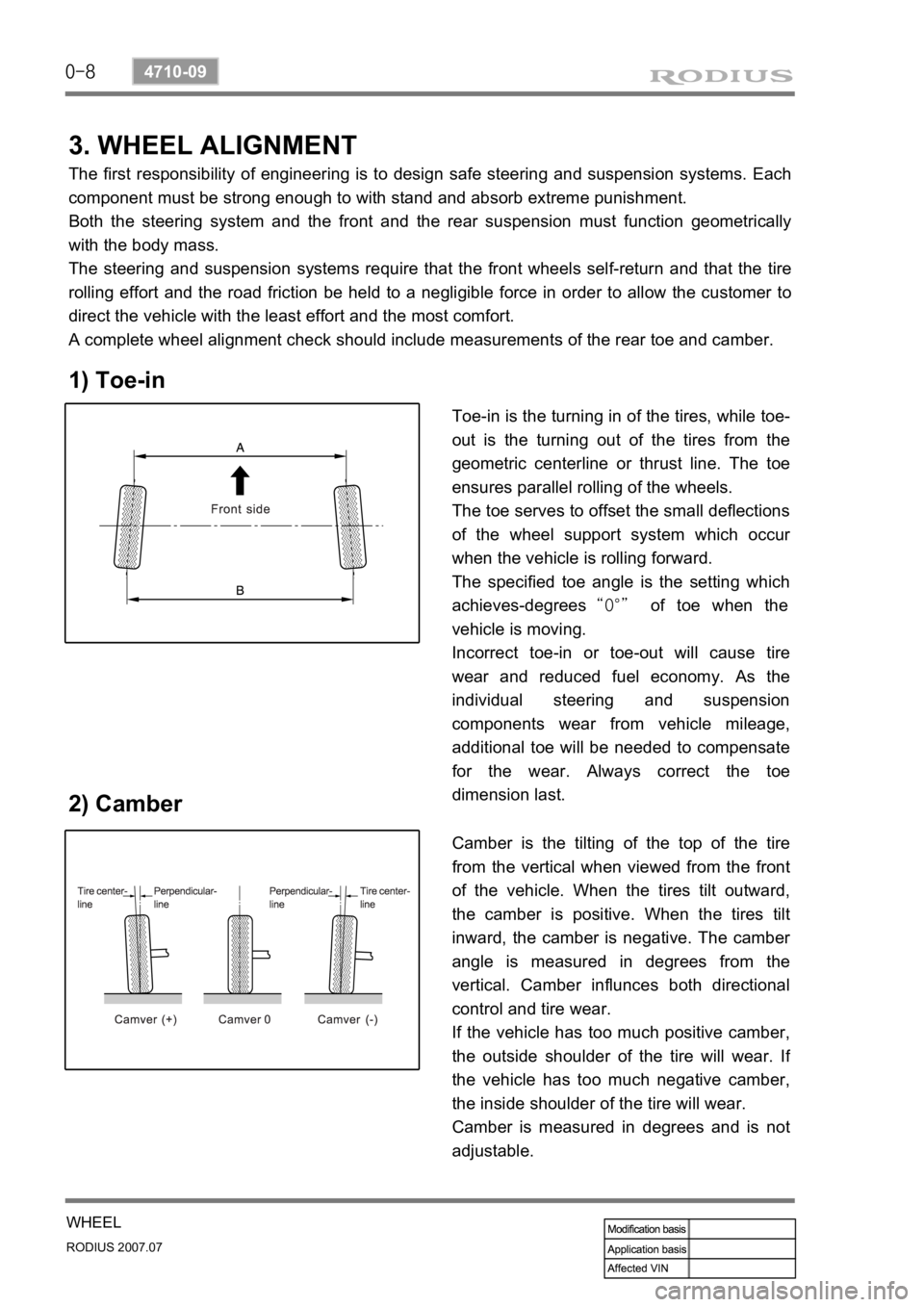
1) Toe-in
2) Camber
Toe-in is the turning in of the tires, while toe-
out is the turning out of the tires from the
geometric centerline or thrust line. The toe
ensures parallel rolling of the wheels.
The toe serves to offset the small deflections
of the wheel support system which occu
r
when the vehicle is rolling forward.
The specified toe angle is the setting which
achieves-degrees “0°” of toe when the
vehicle is moving.
Incorrect toe-in or toe-out will cause tire
wear and reduced fuel economy. As the
individual steering and suspension
components wear from vehicle mileage,
additional toe will be needed to compensate
for the wear. Always correct the toe
dimension last.
Camber is the tilting of the top of the tire
from the vertical when viewed from the front
of the vehicle. When the tires tilt outward,
the camber is positive. When the tires tilt
inward, the camber is negative. The cambe
r
angle is measured in degrees from the
vertical. Camber influnces both directional
control and tire wear.
If the vehicle has too much positive camber,
the outside shoulder of the tire will wear. I
f
the vehicle has too much negative camber,
the inside shoulder of the tire will wear.
Camber is measured in degrees and is not
adjustable.