engine SSANGYONG RODIUS 2007 Owners Manual
[x] Cancel search | Manufacturer: SSANGYONG, Model Year: 2007, Model line: RODIUS, Model: SSANGYONG RODIUS 2007Pages: 465, PDF Size: 56.32 MB
Page 155 of 465

ELECTRIC GENERAL
0000-00
ELECTRIC GENERAL
GENERAL
1. LOCATIONS OF UNITS AND SENSORS
IN PASSENGER COMPARTMENT.........
2. SWITCHES, UNITS AND SENSORS IN
ENGINE COMPARTMENT (EXCEPT
ENGINE RELATED SENSORS AND
UNITS)...................................................
3. SWITCHES IN PASSENGER
COMPARTMENT...................................
4. SYSTEM LAYOUT (BASED ON DVD
SYSTEM EQUIPPED VEHICLE).............
5. WIRING HARNESS ARRANGEMENT.....
6. COMPONENTS LOCATOR....................
ELECTRIC GENERAL ELECTRIC GENERAL ELECTRIC GENERAL
4
6
8
10
12
13
Page 160 of 465

0-6
RODIUS 2006.09
0000-00
ELECTRIC GENERAL
2. SWITCHES, UNITS AND SENSORS IN ENGINE
COMPARTMENT (EXCEPT ENGINE RELATED
SENSORS AND UNITS)
Page 161 of 465

0-7
ELECTRIC GENERAL
RODIUS 2006.09
0000-00
Sub condenser
Theft deterrent horn (under the washer fluid reservoir)
PTC power supply relay
(PTC system equipped vehicle)
ABS (ESP) HECU
(under the battery)
Fuse and relay box in engine compartmentBrake pressure sensor
Page 168 of 465

01-3
FUSE AND RELAY
RODIUS 2006.09
0000-00
8410-01FUSES AND RELAYS
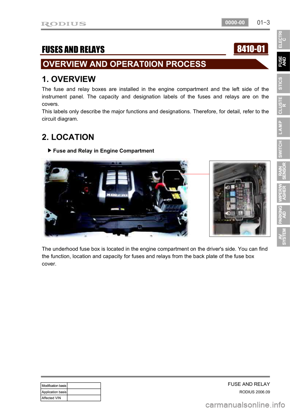
1. OVERVIEW
The fuse and relay boxes are installed in the engine compartment and the left side of the
instrument panel. The capacity and designation labels of the fuses and relays are on the
covers.
This labels only describe the major functions and designations. Therefore, for detail, refer to the
circuit diagram.
2. LOCATION
Fuse and Relay in Engine Compartment
▶
The underhood fuse box is located in the engine compartment on the driver's side. You can find
the function, location and capacity for fuses and relays from the back plate of the fuse box
cover.
Page 170 of 465

01-5
FUSE AND RELAY
RODIUS 2006.09
0000-00
3. CAPACITY AND DESIGNATION
1) Engine Compartment
Page 187 of 465

0-14
RODIUS 2006.09
8710-01
STICS
(3) Speed Sensitive INT (Intermittent) Wiper
For STICS without rain sensor, perform the following operation:
1. Controls the wiper intermittent operation by the values from vehicle speed and volume.
Calculates and converts the Intermittent interval automatically by using the vehicle speed
and INT VOLUME when the ignition switch is in “ON” position and the INT switch is in
“ON” position (the engine is running).
The wipers are operated in vehicle speed sensitive mode when turning the INT switch
to “ON” position with the engine running or starting the engine with the INT switch
positioned “ON”.
Intermittent interval (at 0 km/h): 3 ± 0.5 ~ 19 ± 2 seconds -
-
-
2. Vehicle speed calculation
[Input the vehicle speed]
It is calculated by the numbers of input pulses for one second.
1 [pulses/sec] = 60 [km/h] x 60 [sec] / 637 pulses = 1.41 [km/h]
3. VOLUME calculation
Calculates the INT VOLUME with 5 grades as shown in the table in next page. -
4. Pause time calculation
Pause time: the duration that wipers are stopped at parking position
Elapsed time: the duration after the wiper motor started to operate from parking position
The pause time is calculated by the vehicle speed and VOLUME value as shown in the
table in next page. -
-
-
If the pause time is below 1.0 second, the wipers operate without pause.
If the pause time is over 1.5 seconds, the wipers operate intermittently. ·
·
Page 199 of 465

0-26
RODIUS 2006.09
8710-01
STICS
10) Defogger Timer
The system outp<009c009b009a0047009b008f008c0047009b008800900093008e0088009b008c00530047009e00900095008b009a008f0090008c0093008b004700880095008b00470096009c009b009a0090008b008c00470099008c00880099009d0090008c009e004700
94009000990099009600990047008f008c0088009b008c008b> glass “O
signal when turning on the defogger switch (while the engine is running).
The output stops when turning on the defogger switch again during its operation.
The out
p<009c009b00470090009a004702c80076007502c9004700960095009300a00047008d009600990047005d0047009400900095009c009b008c009a0047004f007b005a00500047009e008f008c00950047009b009c0099009500900095008e004702c8007600
7502c90047009b008f008c00470099008c008800990047008b>efogger switch
within 10 minutes (T2) after completion of output.
When turning on the defogger switch again within 10 minutes (T2) after completion of initial
12 minutes (T1) of output, the output comes on for 6 minutes (T3) again once only.
<007b008f008c00470096009c009b0097009c009b0047009a009b00960097009a0047009e008f008c00950047009b008f008c00470070006e0075004700590047009a009e0090009b008a008f00470090009a0047009b009c00990095008c008b0047009b00
96004702c80076006d006d02c9004700970096009a0090009b>ion or the ALT is
“OFF”. 1.
2.
3.
4.
Page 200 of 465

0-27
STICS
RODIUS 2006.09
8710-01
This vehicle has the windshield heated glass and the tailgate and outside rearview mirror
heated glass. The heater relay in the ICM box controls the tailgate and outside rearview mirro
r
heated glass and its fuse (15A) is located in the engine compartment fuse box.
Defogger switch
Page 212 of 465

0-39
STICS
RODIUS 2006.09
8710-01
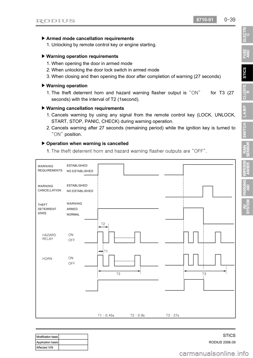
Armed mode cancellation requirements ▶
Unlocking by remote control key or engine starting. 1.
Warning operation requirements ▶
When opening the door in armed mode
When unlocking the door lock switch in armed mode
When closing and then opening the door after completion of warning (27 seconds) 1.
2.
3.
Warning operation ▶
The theft deterrent horn and hazard warning flasher output is “ON” for T3 (27
seconds) with the interval of T2 (1second). 1.
Warning cancellation requirements ▶
Cancels warning by using any signal from the remote control key (LOCK, UNLOCK,
START, STOP, PANIC, CHECK) during warning operation.
Cancels warning after 27 seconds (remaining period) while the ignition key is turned to
“ON” position. 1.
2.
Operation when warning is cancelled ▶
<007b008f008c0047009b008f008c008d009b0047008b008c009b008c00990099008c0095009b0047008f009600990095004700880095008b0047008f008800a100880099008b0047009e00880099009500900095008e0047008d00930088009a008f008c00
9900470096009c009b0097009c009b009a004700880099008c> “OFF”. 1.
Page 213 of 465

0-40
RODIUS 2006.09
8710-01
STICS
15) PANIC Warning
The PANIC warning output is “ON” (theft deterrent horn) when receiving the PANIC
signal from the remote control key (pressing PANIC button for less than 0.5 ~ 1.0 second).
The PANIC warning output is “OFF” when receiving any signal from the remote control
key during PANIC warning.
Followings are theft deterrent warnings: 1.
2.
3.
This function operates only in armed mode.
The system sends the current vehicle conditions (LOCK, engine running) when the PANIC
warning is turned off by the remote control key. 4.
5.The theft deterrent warning is canceled when receiving PANIC signal from the remote
control key during theft deterrent.
The theft deterrent warning output is “ON” when the theft deterrent conditions are
established during PANIC warning (PANIC output is “OFF”).
The PANIC warning output is “ON” when receiving the PANIC signal from the remote
control key in Armed Ready / Armed / Warning Completion / Relock Ready mode
(maintaining the theft deterrent mode). 1)
2)
3)