sensor SSANGYONG RODIUS 2007 Owner's Manual
[x] Cancel search | Manufacturer: SSANGYONG, Model Year: 2007, Model line: RODIUS, Model: SSANGYONG RODIUS 2007Pages: 465, PDF Size: 56.32 MB
Page 149 of 465
0-12
RODIUS 2006.09
0000-00
CDEF(Catalytic Disel Particulate Filter)
6) CDPF Over Load (Notice of Beginning CPF Regeneration Mode
- P1430)
The CDPF system enters the regeneration mode when the mileage is around 600 ~ 1,200
km, depending on the driving condition and driving habits. At this moment, the ECU
performs the CDPF regeneration process; however, the driver may not notice anything
because there is no engine warning or other signals indicating such process.
The control logic in the regeneration process is to increase the exhaust gas temperature by
increasing the fuel injection during post injection process and controlling the intake ai
r
amount(throttle body), and no significant change can be noticed in the vehicle condition.
The engine CHECK lamp flashes but there is no decrease in engine torque.
The engine CHECK lamp flashes to inform the driver when there is an over load due to soot
accumulation because the regeneration temperature cannot be reached due to low speed,
even though CDPF regeneration is in process.
The CDPF regeneration process must be completed by driving for 15-20 minutes at a speed
higher than 80 km/h to solve this problem.
The engine CHECK lamp flashes when CDPF is over loaded; therefore, 4) above must be
performed in this case. 1.
2.
3.
4.
5.
7) CDPF's Excessive Soot Accumulation (P0432)
When the vehicle is driven at a low speed (5-10 km/h) for a long time or long distance, the
soot over accumulates inside the CDPF and the combustion temperature cannot be reached
even by performing the soot combustion process. In this case, this DTC is generated.
This is more serious situation than the CDPF over load condition. Therefore, the engine
power is decreased to protect the system and the engine CHECK lamp is turned on.
Blow the soot between the engine and the exhaust system several times and clear the DTC
to solve this problem. If the same DTC is generated again, check the system according to
the DTC description related to the differential pressure sensor.
* This DTC is actually generated mostly due to the related system malfunction, such as
differential pressure sensor malfunction. 1.
2.
3.
Page 155 of 465
ELECTRIC GENERAL
0000-00
ELECTRIC GENERAL
GENERAL
1. LOCATIONS OF UNITS AND SENSORS
IN PASSENGER COMPARTMENT.........
2. SWITCHES, UNITS AND SENSORS IN
ENGINE COMPARTMENT (EXCEPT
ENGINE RELATED SENSORS AND
UNITS)...................................................
3. SWITCHES IN PASSENGER
COMPARTMENT...................................
4. SYSTEM LAYOUT (BASED ON DVD
SYSTEM EQUIPPED VEHICLE).............
5. WIRING HARNESS ARRANGEMENT.....
6. COMPONENTS LOCATOR....................
ELECTRIC GENERAL ELECTRIC GENERAL ELECTRIC GENERAL
4
6
8
10
12
13
Page 158 of 465
0-4
RODIUS 2006.09
0000-00
ELECTRIC GENERAL
0000-00ELECTRIC GENERAL
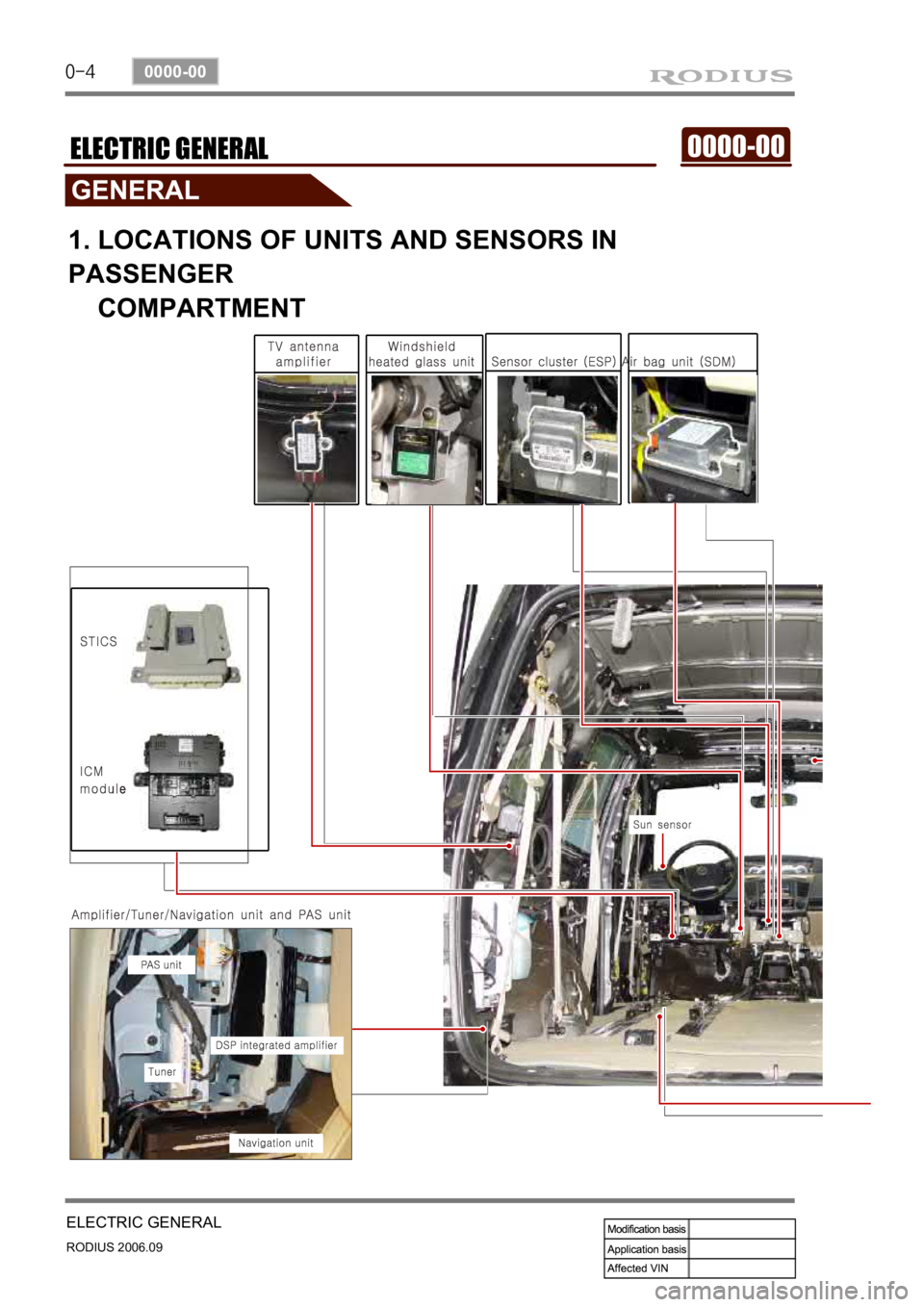
1. LOCATIONS OF UNITS AND SENSORS IN
PASSENGER
COMPARTMENT
Page 160 of 465

0-6
RODIUS 2006.09
0000-00
ELECTRIC GENERAL
2. SWITCHES, UNITS AND SENSORS IN ENGINE
COMPARTMENT (EXCEPT ENGINE RELATED
SENSORS AND UNITS)
Page 161 of 465

0-7
ELECTRIC GENERAL
RODIUS 2006.09
0000-00
Sub condenser
Theft deterrent horn (under the washer fluid reservoir)
PTC power supply relay
(PTC system equipped vehicle)
ABS (ESP) HECU
(under the battery)
Fuse and relay box in engine compartmentBrake pressure sensor
Page 178 of 465
0-5
STICS
RODIUS 2006.09
8710-01
The STICS in this vehicle has similar functions with the one used in the new Rexton. Additional
function of diagnosing through SCAN-Tool has been added into new STICS.
The major difference in hardware-wise is that STICS receives vehicle collision signal from G-
sensor in the airbag module to activate automatic door unlock function when the vehicle
collided over 15 km/h of vehicle speed.
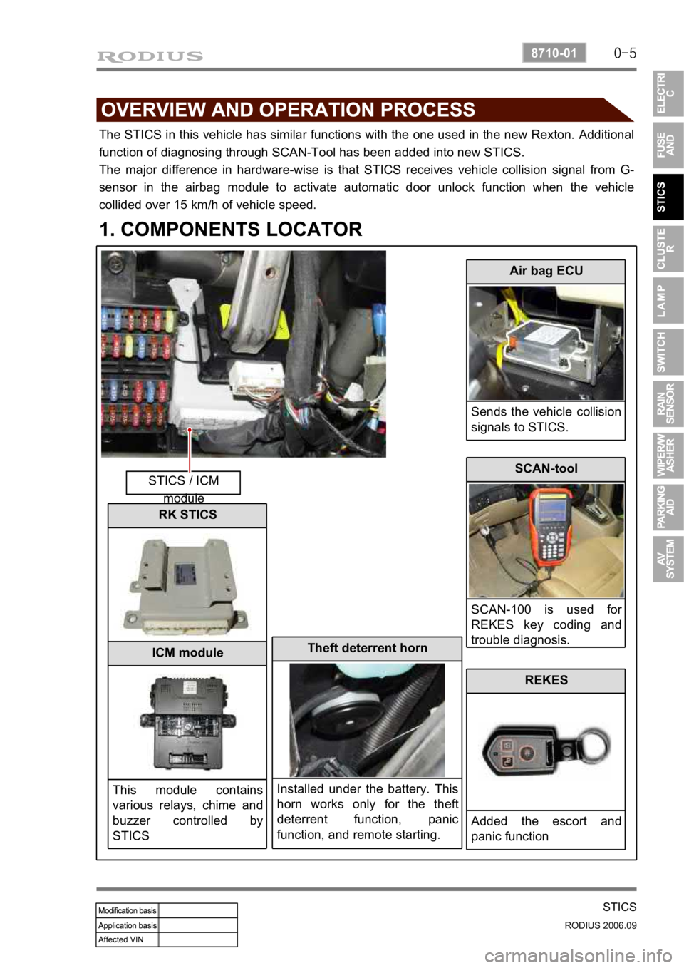
1. COMPONENTS LOCATOR
STICS / ICM module
Air bag ECU
Sends the vehicle collision
signals to STICS.
Theft deterrent horn
Installed under the battery. This
horn works only for the theft
deterrent function, panic
function, and remote starting.
SCAN-tool
SCAN-100 is used fo
r
REKES key coding and
trouble diagnosis.
REKES
Added the escort and
panic function
RK STICS
ICM module
This module contains
various relays, chime and
buzzer controlled by
STICS
Page 182 of 465

0-9
STICS
RODIUS 2006.09
8710-01
(2) Rain Sensor Coupled Wiper
If equipped with RE-STICS rain sensor, has following operation system.
System layout ▶
This vehicle has a different wiper control logic compared to other models. As shown in the
system diagram, the rain sensor unit does not control wiper directly. The rain sensor unit sends
infrared rays signal through LED and then receives it with photo diode and then sends the
returned signal to STICS and the STICS controls the wipers directly.
For more details, refer to rain sensing wiper section in this manual.
Page 183 of 465

0-10
RODIUS 2006.09
8710-01
STICS
Rain sensing operation point ▶
The wiper relay is turned on and the wiper motor runs one cycle when the ignition key is
turned to “ON” position (while the wiper switch is in “AUTO” position).
The wiper relay (LO) is turned on and the wiper motor runs one cycle when changing the
wiper switch to “AUTO” position from any other positions (while the ignition key is in
“ON” position). When the wiper switch is turned to “AUTO” position again from other
positions, the system drives the wiper relay (LO) to run the wiper motor one cycle only when
the rain sensor detects the “Rain Detected” signal. 1)
2)
Rain sensing sensitivity control ▶
The wiper relay is turned on and the wiper motor runs one cycle when the volume sensitivity is
increased (ex: from 0 to 1) (while the ignition key is in “ON” position, the wiper switch is
in “AUTO” position, and the wiper motor is in “Parked” position). However, the wiper
motor can be operated only when the rain sensor detects the “Rain Detected” signal.
* If the volume sensitivity is changed more than 2 stages within 2 seconds, the wiper motor runs
only one cycle.
Page 184 of 465
0-11
STICS
RODIUS 2006.09
8710-01
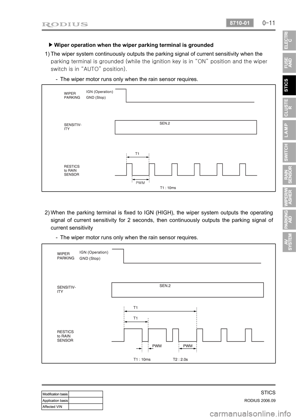
Wiper operation when the wiper parking terminal is grounded ▶
The wiper system continuously outputs the parking signal of current sensitivity when the
<009700880099009200900095008e0047009b008c00990094009000950088009300470090009a0047008e00990096009c0095008b008c008b0047004f009e008f00900093008c0047009b008f008c00470090008e00950090009b0090009600950047009200
8c00a000470090009a004700900095004702c80076007502c9> position and the wiper
switch is in “AUTO” position). 1)
The wiper motor runs only when the rain sensor requires. -
When the parking terminal is fixed to IGN (HIGH), the wiper system outputs the operating
signal of current sensitivity for 2 seconds, then continuously outputs the parking signal o
f
current sensitivity 2)
The wiper motor runs only when the rain sensor requires. -
Page 185 of 465

0-12
RODIUS 2006.09
8710-01
STICS
Defective rain sensor ▶
The wiper relay (LO) is turned on and the wiper motor runs one cycle when the wipe
r
sensitivity is changed to 2 from 3 during receiving the malfunction signal (1) from the rain
sensor (while the ignition key is in “ON” position and the wiper switch is in “AUTO”
position). 1)
The wiper relay (LO) is turned on and the wiper motor runs one cycle when the wiper
sensitivity is changed to 3 from 4 during receiving the malfunction signal (2) from the rain
sensor (while the ignition key is in “ON” position and the wiper switch is in “AUTO”
position). 2)