SSANGYONG RODIUS 2012 Service Manual
RODIUS 2012
SSANGYONG
SSANGYONG
https://www.carmanualsonline.info/img/67/57525/w960_57525-0.png
SSANGYONG RODIUS 2012 Service Manual
Page 143 of 715
02-70000-00
4620-02 Power Steering Gear
- Changed tie rod end
Newly Installed Equipment
Located in left quarter trim
Repair kit
Sealant
Front
Front
2WD
(A/T, M/T)4WD (A/T)2WD
(A/T, M/T)
Wheel and Tire Repair Kit
4170-07 Wheel
- For 4WD vehicle, installed new wheel
- New wheel
- Installed tire repair kit
3170-01Manual Transmission
- Installed 6-speed manual
transmission
1990-10Transmission Cross Member
- Changed cross member
Page 156 of 715
01-14
Name SizeNumbers of
fastenerTightening
torque (Nm)Note (total
tightening
torque)
Idler pulley/tensioner
pulley1 45±4.5Nm -
Glow plug M5 4 20±2Nm -
Vacuum pumpM8×25 3 10±1Nm -
Timing gear case coverM6×40 7 10±1Nm -
M6×45 1 10±1Nm -
M6×50 3 10±1Nm -
Cylinder head coverM6×35 21 10±1Nm -
Oil dipstick gauge coverM6×16 1 10±1Nm -
Oil filter cap 1 25±2.5Nm -
Fuel railM8×25 2 25±2.5Nm -
Injector clamp boltM6×44 2 9±1.0Nm
130˚±10˚ -
High pressure pipe
(between high pressure
pump and fuel rail
assembly)M17 1 30±3Nm -
High pressure pipe
(between fuel rail
assembly and injector)M17 4 30±3Nm -
Crankshaft position sensorM5×14 1 8±0.4Nm -
Main wiringM6×16 5 10±1Nm -
Intake ductM8×25 3 25±2.5Nm -
Power steering pumpM8×100 3 25±2.5Nm -
Cylinder head front coverM6×10 5 10±1Nm -
Ladder frameM8×16 5 30±3Nm -
Page 163 of 715
02-6
Cylinder head coverM6×352110±1Nm-
Oil gauge tubeM6×16110±1Nm-
Oil filter cap 125±2.5Nm-
Fuel railM8×25225±2.5Nm-
Injector clamp boltM6×4429±1.0Nm
130˚±10˚-
High pressure pipe
(between HP pump and
fuel rail)M17 130±3Nm-
High pressure pipe
(between fuel rail and
injector)M17 430±3Nm-
Crank position sensorM5×1418±0.4Nm-
Main wiringM6×16510±1Nm-
Intake ductM8×25325±2.5Nm-
Power steering pumpM8×100325±2.5Nm-
Cylinder head front
coverM6×10510±1Nm-
Ladder frame M8x16 530±3Nm-
Component SizeBolt
QuantitySpecified torque
(Nm)Remark
(Total torque)
Glow plug M5 420±2Nm-
Vacuum pumpM8×25310±1Nm-
Timing gear case coverM6×40710±1Nm-
M6×45110±1Nm-
M6×50310±1Nm-
Page 181 of 715
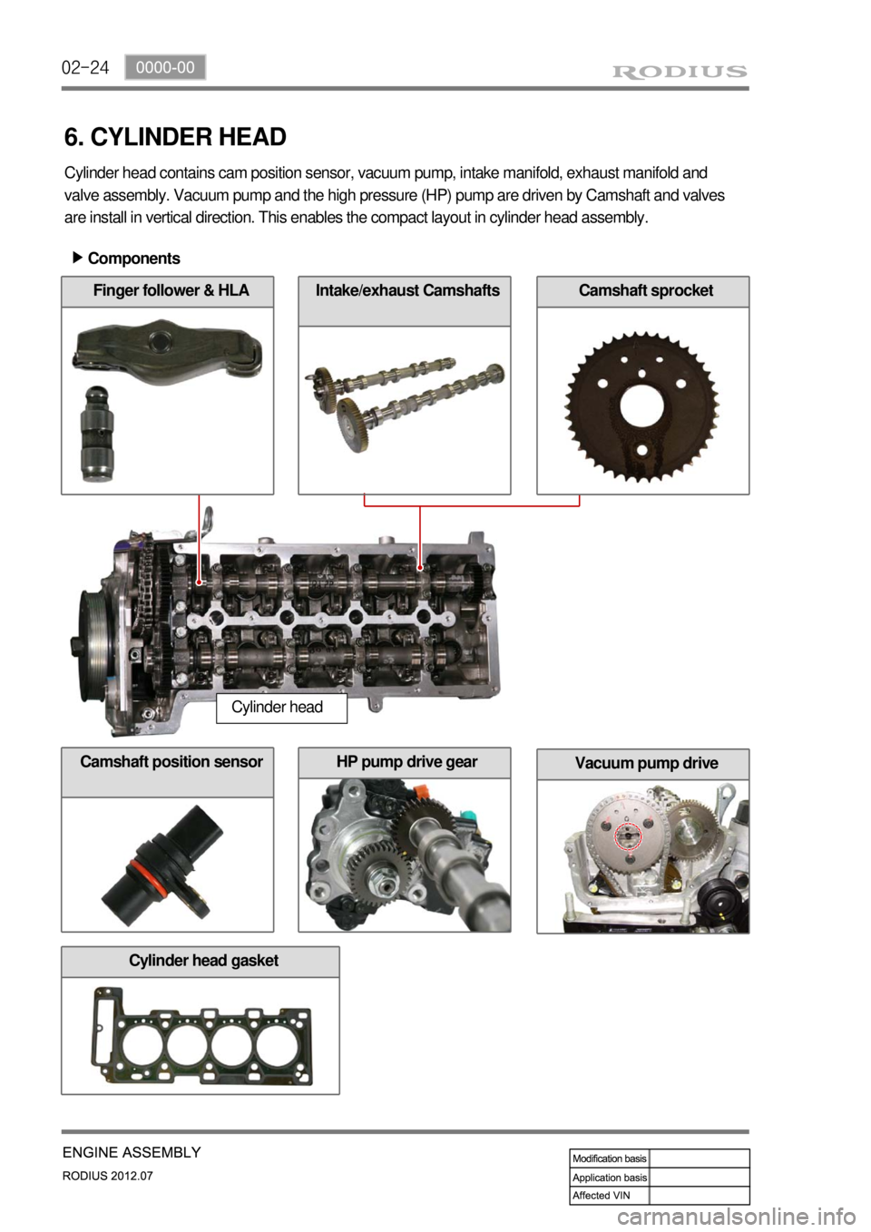
02-24
Vacuum pump driveHP pump drive gear
Cylinder head gasket
Camshaft position sensor
Components ▶
Cylinder head
Cylinder head contains cam position sensor, vacuum pump, intake manifold, exhaust manifold and
valve assembly. Vacuum pump and the high pressure (HP) pump are driven by Camshaft and valves
are install in vertical direction. This enables the compact layout in cylinder head assembly.
6. CYLINDER HEAD
Finger follower & HLACamshaft sprocketIntake/exhaust Camshafts
Page 183 of 715
02-26
Intake/Exhaust Camshafts
2) Camshaft
(1) Overview
Hollow type camshaft contains cam, octagon cam, HP pump gear and intake/exhaust gears.
Camshaft operates the intake/exhaust valves, vacuum pump and HP pump, and transfers the
engine oil to vacuum pump through the internal oil passage.
(2) Location
Exhaust CamshaftExhaust Camshaft
Thrust journalIntake Camshaft
Closed flow type water jacket (improving cooling performance) ▶
Octagon cam
(for tooling)
Connected to
vacuum pump
Page 186 of 715
02-290000-00
1) Chain Drive
(1) Overview
The drive chain is single chain drive system with simple design and variable performance, and it
utilizes the hydraulic tensioner to reduce the wave impact generated by the chain. This chain is light
weight and has high durability through single bush chain. Shoulder bolts are used for better NHV.
7. CHAIN AND GEAR DRIVE SYSTEM
D20DTR engine uses single stage chain drive system. Timing chain drives the exhaust side and
gear drive the intake side. Timing chain is single bush type. Upper chain drives HP pump
connected to intake Camshaft by driving exhaust cam shift sprocke, and lower chain drives oil
pump to lubricate the engine.
Page 188 of 715
02-310000-00
2) Timing Chain and Gear
(1) Timing chain
Simple layout: optimized timing, enhanced
NVH
Single stage layout: minimized chain load
The brass link on crankshaft is at
symmetric position of that on camshaft. -
-
-
Chain upper bush
- Single bush type (112 EA)
Chain lower bush
- Single bush type (60 EA)
(2) Tensioner
Tensioner adjusts the chain tension to keep it tight during engine running. This reduces the wear
in guide rail and spoke.
Operating principle
- Use the spring tension in tensioner and hydraulic pressure
Tensioner type
- Compensation and impact absorbing
Static and dynamic force
- Spring + Hydraulic pressure 1.
2.
3.
Plunger
HousingSpring
Check valve
Hydraulic tensioner assembly ▶
Page 190 of 715
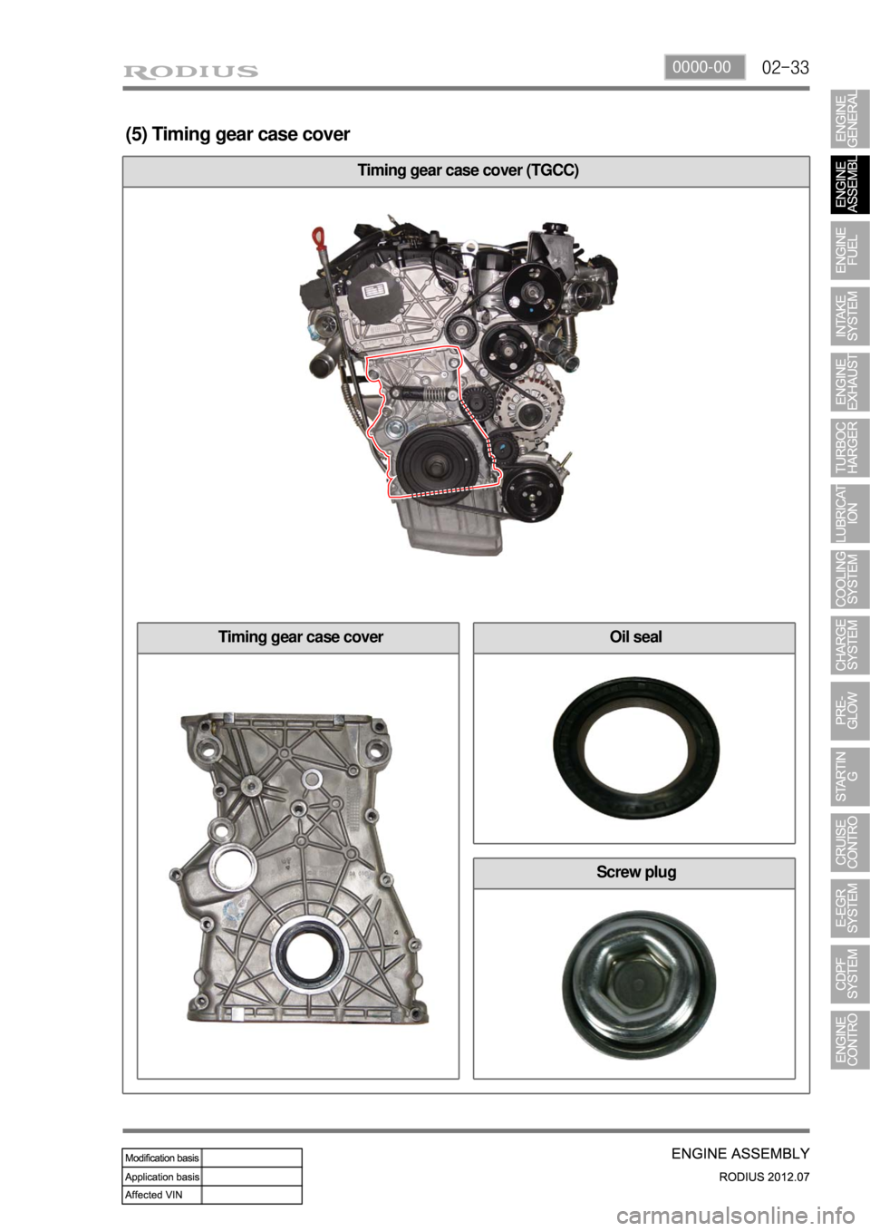
02-330000-00
Screw plug
Oil sealTiming gear case cover
Timing gear case cover (TGCC)
(5) Timing gear case cover
Page 191 of 715
02-34
Features
Major function: Protecting the chain drive system, minor function: Shielding the chain noise.
Install crankshaft front seal and screw plug on the timing gear case cover. ▶
-
-
Do not touch the inner lip of crankshaft front seal.
Be careful not to damage the screw thread when removing the lock pin to release the chain
tensioner.
Be careful not to damage the O-ring when installing the screw plug. -
-
-
A671 997 01 46
Crankshaft front seal
Location of chain tensioner
screw plug
Page 193 of 715
02-36
9. DUAL MASS FLYWHEEL (DMF) & DRIVE PLATE
1) Overview
Flywheel is installed on crankshaft. When
starting the engine, this functions as follows:
Reducing the irregular speed of crankshaft
due to unbalanced combustion ->
Improving the power train NVH, Improving
the driving performance
Reducing the clutch noise by using ball
bearing
Improving the durability of DMF by using
strong arch spring -
-
-
2) Layout
Spring guide
Drive plate
Primary cover
Primary flywheel
Internal/external ringSecondary flywheel
Ring gear


