steering SSANGYONG RODIUS 2012 Service Manual
[x] Cancel search | Manufacturer: SSANGYONG, Model Year: 2012, Model line: RODIUS, Model: SSANGYONG RODIUS 2012Pages: 715, PDF Size: 79.36 MB
Page 143 of 715

02-70000-00
4620-02 Power Steering Gear
- Changed tie rod end
Newly Installed Equipment
Located in left quarter trim
Repair kit
Sealant
Front
Front
2WD
(A/T, M/T)4WD (A/T)2WD
(A/T, M/T)
Wheel and Tire Repair Kit
4170-07 Wheel
- For 4WD vehicle, installed new wheel
- New wheel
- Installed tire repair kit
3170-01Manual Transmission
- Installed 6-speed manual
transmission
1990-10Transmission Cross Member
- Changed cross member
Page 146 of 715

01-4
2. MAJOR COMPONENTS
Front view ▶
Vacuum pump
Camshaft position sensor
Oil filter assembly
Power steering pump pulley
Oil pressure switch
Water pump pulley
Idler pulley No. 22
Alternator pulley
Auto tensioner
Idler pulley No. 1
A/C compressor pulley
Rear view ▶
E-EGR valve
Fuel temperature sensor
Fuel HP pump assembly
Coolant temperature sensor
Crankshaft position sensorIMV valve
Isolation damper
Page 148 of 715

01-6
3. ENGINE COMPARTMENT LAYOUT
Do not work on the engine compartment while the engine, radiator, exhaust manifold, muffler
or catalytic converter is hot. Always turn the engine off and allow it to cool before starting the
maintenance.
Regularly check the engine oil level and add Ssangyong genuine engine oil if necessary.
Clean the dipstick with clean cloth so that any foreign materials cannot get into the engine. -
-
-
Power steering fluid
reservoir Brake fluid reservoir
Engine oil
dipstick gauge
Washer fluid
reservoir cap Engine oil filler cap
Air cleaner
Operating vehicle with insuffi cient amount of oil can damage the engine. Make sure the
engine oil level is correct and add oil if necessary.
Coolant reservoir
Battery
Fuse & relay
Page 156 of 715

01-14
Name SizeNumbers of
fastenerTightening
torque (Nm)Note (total
tightening
torque)
Idler pulley/tensioner
pulley1 45±4.5Nm -
Glow plug M5 4 20±2Nm -
Vacuum pumpM8×25 3 10±1Nm -
Timing gear case coverM6×40 7 10±1Nm -
M6×45 1 10±1Nm -
M6×50 3 10±1Nm -
Cylinder head coverM6×35 21 10±1Nm -
Oil dipstick gauge coverM6×16 1 10±1Nm -
Oil filter cap 1 25±2.5Nm -
Fuel railM8×25 2 25±2.5Nm -
Injector clamp boltM6×44 2 9±1.0Nm
130˚±10˚ -
High pressure pipe
(between high pressure
pump and fuel rail
assembly)M17 1 30±3Nm -
High pressure pipe
(between fuel rail
assembly and injector)M17 4 30±3Nm -
Crankshaft position sensorM5×14 1 8±0.4Nm -
Main wiringM6×16 5 10±1Nm -
Intake ductM8×25 3 25±2.5Nm -
Power steering pumpM8×100 3 25±2.5Nm -
Cylinder head front coverM6×10 5 10±1Nm -
Ladder frameM8×16 5 30±3Nm -
Page 163 of 715

02-6
Cylinder head coverM6×352110±1Nm-
Oil gauge tubeM6×16110±1Nm-
Oil filter cap 125±2.5Nm-
Fuel railM8×25225±2.5Nm-
Injector clamp boltM6×4429±1.0Nm
130˚±10˚-
High pressure pipe
(between HP pump and
fuel rail)M17 130±3Nm-
High pressure pipe
(between fuel rail and
injector)M17 430±3Nm-
Crank position sensorM5×1418±0.4Nm-
Main wiringM6×16510±1Nm-
Intake ductM8×25325±2.5Nm-
Power steering pumpM8×100325±2.5Nm-
Cylinder head front
coverM6×10510±1Nm-
Ladder frame M8x16 530±3Nm-
Component SizeBolt
QuantitySpecified torque
(Nm)Remark
(Total torque)
Glow plug M5 420±2Nm-
Vacuum pumpM8×25310±1Nm-
Timing gear case coverM6×40710±1Nm-
M6×45110±1Nm-
M6×50310±1Nm-
Page 170 of 715

02-130000-00
D20DTR Engine
1. BELT LAYOUT
It is single drive type and uses FEAD (Front End Accessories Drive) design to make a compact
layout.
Components ▶
HPS
(Hydraulic Power Steering)
1 Crankshaft pulley (DDU)
2 Auto tensioner
3 Tensioner pulley
4 Vacuum pump
5 A/C compressor pulley
6 Alternator pulley
7 Water pump pulley
8 Idle pulley #1
9 Idle pulley #2
10 Power steering pump pulley
Page 343 of 715

15-18
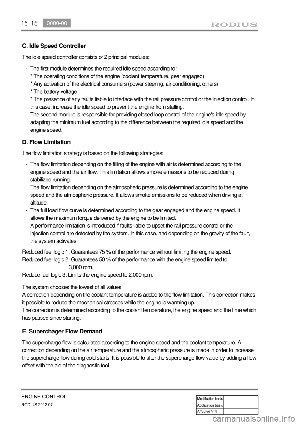
C. Idle Speed Controller
The idle speed controller consists of 2 principal modules:
The first module determines the required idle speed according to:
* The operating conditions of the engine (coolant temperature, gear engaged)
* Any activation of the electrical consumers (power steering, air conditioning, others)
* The battery voltage
* The presence of any faults liable to interface with the rail pressure control or the injection control. In
this case, increase the idle speed to prevent the engine from stalling.
The second module is responsible for providing closed loop control of the engine's idle speed by
adapting the minimum fuel according to the difference between the required idle speed and the
engine speed. -
-
D. Flow Limitation
The flow limitation strategy is based on the following strategies:
The flow limitation depending on the filling of the engine with air is determined according to the
engine speed and the air flow. This limitation allows smoke emissions to be reduced during
stabilized running.
The flow limitation depending on the atmospheric pressure is determined according to the engine
speed and the atmospheric pressure. It allows smoke emissions to be reduced when driving at
altitude.
The full load flow curve is determined according to the gear engaged and the engine speed. It
allows the maximum torque delivered by the engine to be limited.
A performance limitation is introduced if faults liable to upset the rail pressure control or the
injection control are detected by the system. In this case, and depending on the gravity of the fault,
the system activates: -
-
-
-
Reduced fuel logic 1: Guarantees 75 % of the performance without limiting the engine speed.
Reduced fuel logic 2: Guarantees 50 % of the performance with the engine speed limited to
3,000 rpm.
Reduce fuel logic 3: Limits the engine speed to 2,000 rpm.
The system chooses the lowest of all values.
A correction depending on the coolant temperature is added to the flow limitation. This correction makes
it possible to reduce the mechanical stresses while the engine is warming up.
The correction is determined according to the coolant temperature, the engine speed and the time which
has passed since starting.
E. Superchager Flow Demand
The supercharge flow is calculated according to the engine speed and the coolant temperature. A
correction depending on the air temperature and the atmospheric pressure is made in order to increase
the supercharge flow during cold starts. It is possible to alter the supercharge flow value by adding a flow
offset with the aid of the diagnostic tool
Page 489 of 715

06-4
4WD Switch, Headlamp
Leveling Switch, Rear Wipe
Switch
Outside Rearview
Mirror
Adjusting/Folding
Switches
Remote Control Switches on Steering Wheel
Window switch
1. LAYOUT
Volume button
Seek buttonManual gear shift
down switch
Power buttonManual gear shift
up switch
Mode button
Mute button
Bluetooth switch
Page 490 of 715

06-58510-00
Passenger’s Window Switch
(same with rear window
switches)
Multifunction Switch and Steering Wheel Angle
Sensor
Room Lamp and Sunroof Switch (w/
multimeter)
Defogger switchPassenger’s seat
warmer switch Rear fog lamp
switch Driver’s seat warmer
switchFront fog
lamp switch
Hazard warning
flasher switchESP OFF
switch
Door coupled
room lamp switch
Sunroof switch
Multimeter
Front room lamp switch
Page 611 of 715

09-34891-01
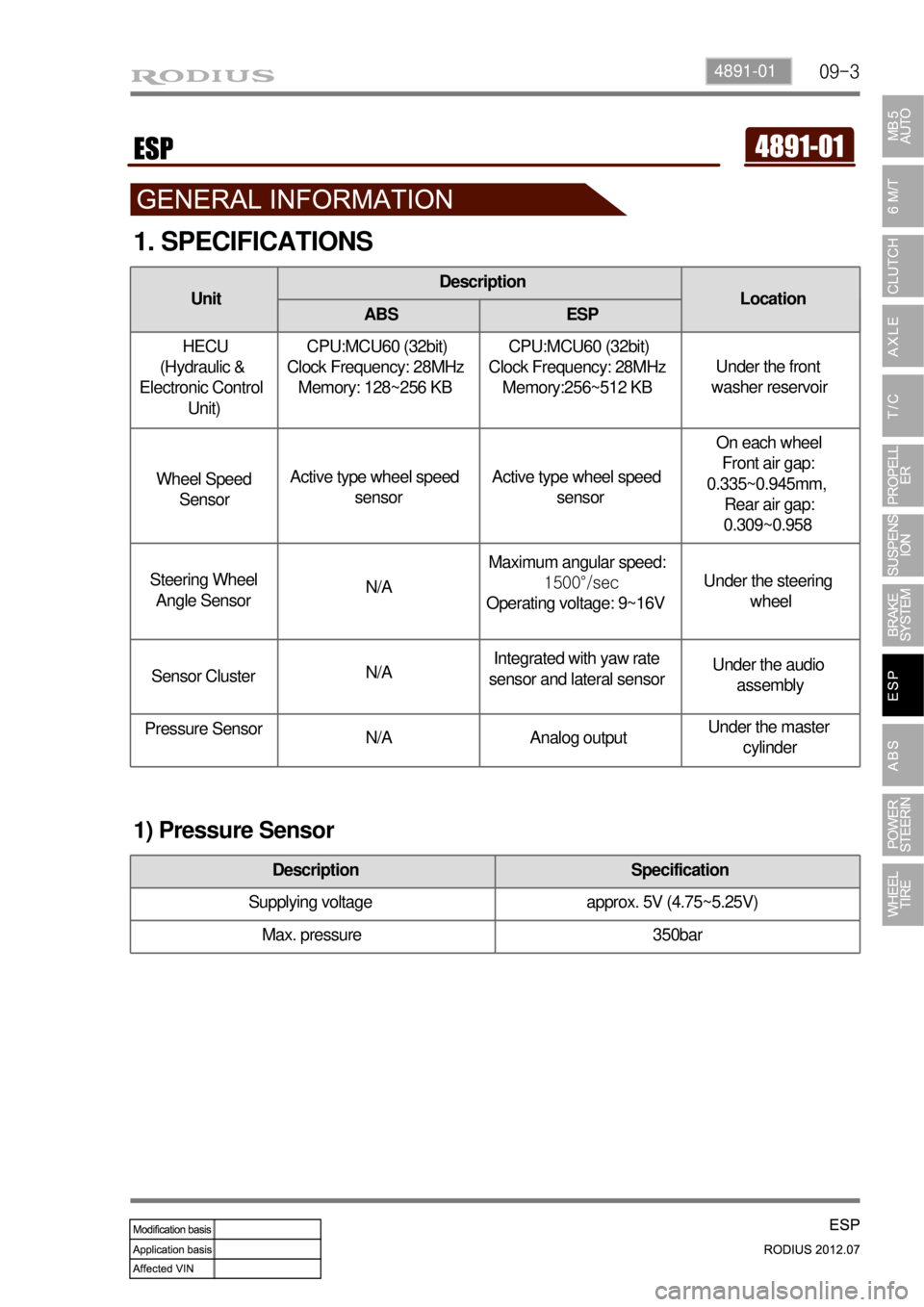
1. SPECIFICATIONS
1) Pressure Sensor
UnitDescription
Location
ABS ESP
HECU
(Hydraulic &
Electronic Control
Unit) CPU:MCU60 (32bit)
Clock Frequency: 28MHz
Memory: 128~256 KB CPU:MCU60 (32bit)
Clock Frequency: 28MHz
Memory:256~512 KB Under the front
washer reservoir
Wheel Speed
SensorActive type wheel speed
sensorActive type wheel speed
sensorOn each wheel
Front air gap:
0.335~0.945mm,
Rear air gap:
0.309~0.958
Steering Wheel
Angle SensorN/AMaximum angular speed:
1500°/sec
Operating voltage: 9~16VUnder the steering
wheel
Sensor ClusterN/AIntegrated with yaw rate
sensor and lateral sensorUnder the audio
assembly
Pressure Sensor
N/A Analog outputUnder the master
cylinder
Description Specification
Supplying voltage approx. 5V (4.75~5.25V)
Max. pressure 350bar