sensor SSANGYONG TURISMO 2013 Workshop Manual
[x] Cancel search | Manufacturer: SSANGYONG, Model Year: 2013, Model line: TURISMO, Model: SSANGYONG TURISMO 2013Pages: 796, PDF Size: 78.99 MB
Page 333 of 796
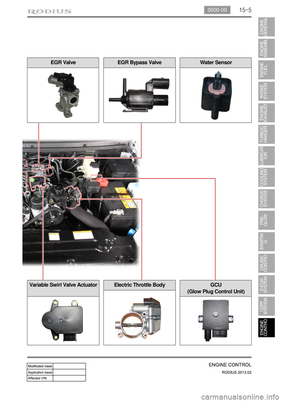
15-50000-00
GCU
(Glow Plug Control Unit)
EGR Bypass ValveEGR Valve
Electric Throttle Body
Water Sensor
Variable Swirl Valve Actuator
Page 334 of 796
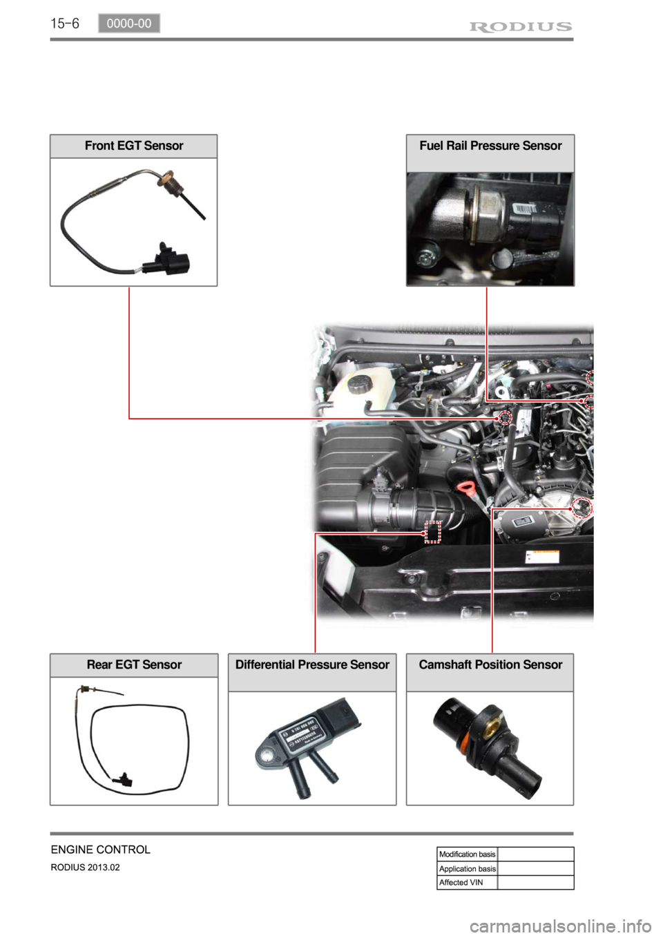
15-6
Fuel Rail Pressure SensorFront EGT Sensor
Differential Pressure SensorCamshaft Position SensorRear EGT Sensor
Page 335 of 796
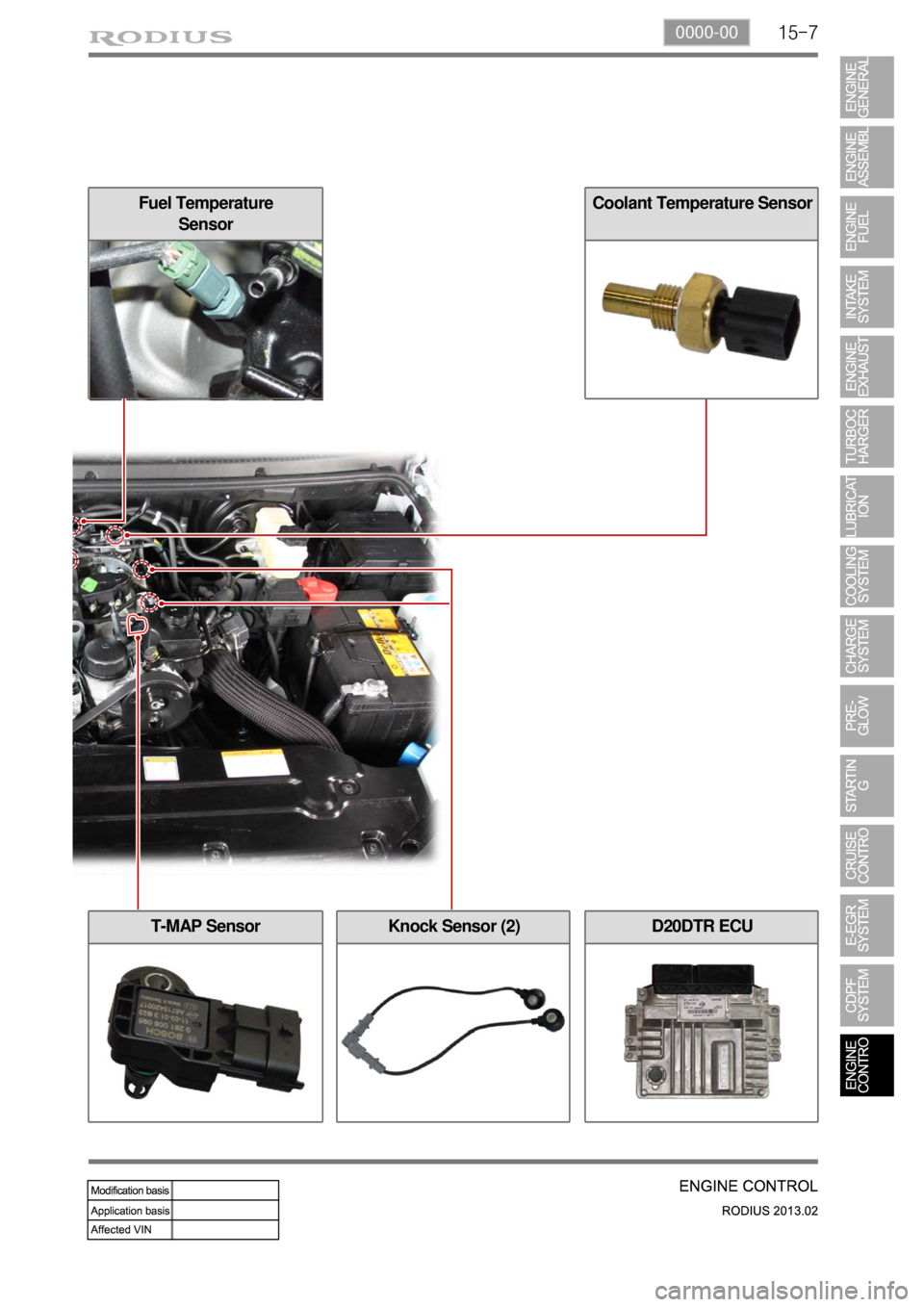
15-70000-00
Fuel Temperature
SensorCoolant Temperature Sensor
Knock Sensor (2)T-MAP SensorD20DTR ECU
Page 337 of 796
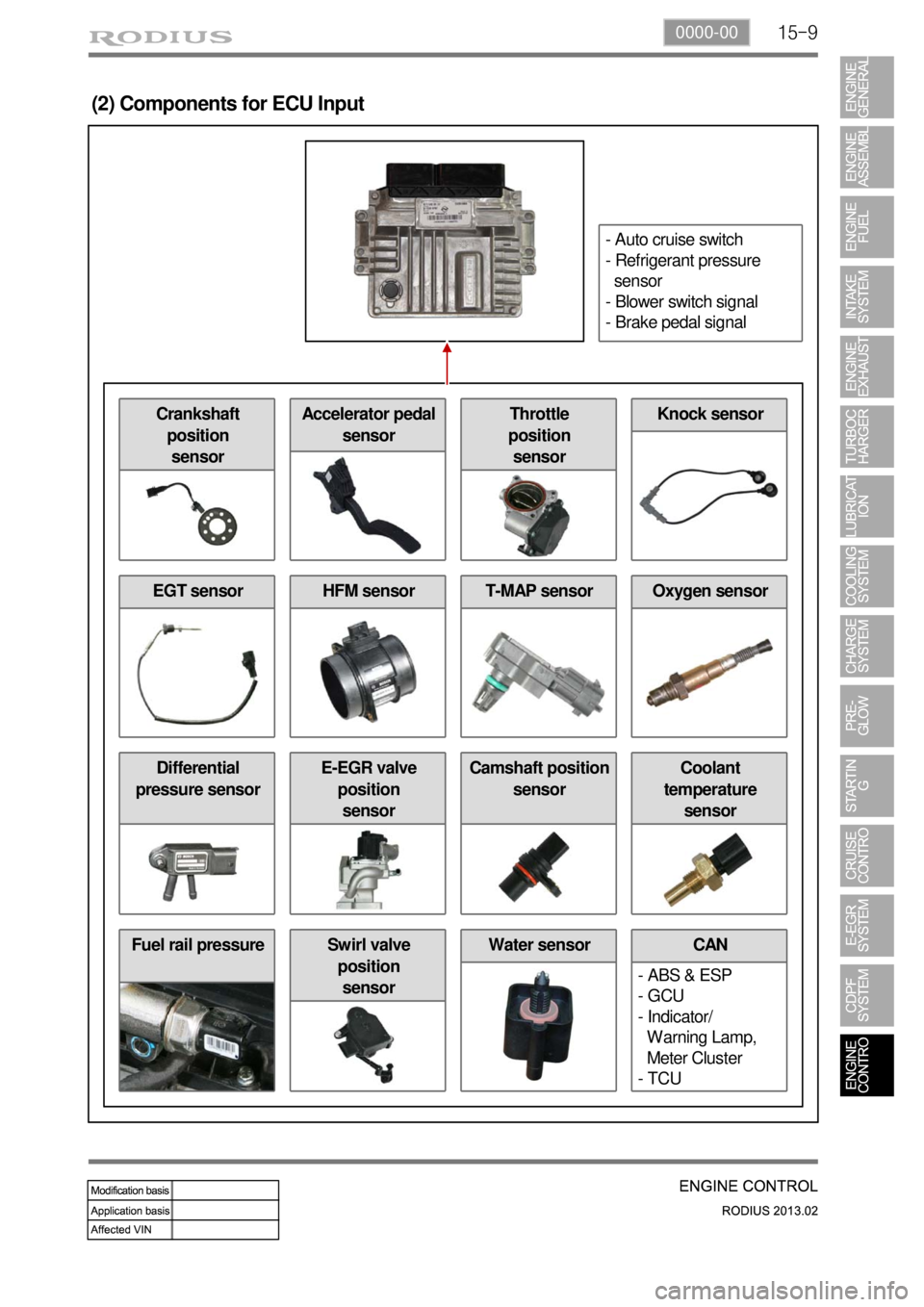
15-90000-00
Fuel rail pressure Water sensor
(2) Components for ECU Input
CAN
- ABS & ESP
- GCU
- Indicator/
Warning Lamp,
Meter Cluster
- TCUSwirl valve
position
sensor
Differential
pressure sensorE-EGR valve
position
sensorCamshaft position
sensorCoolant
temperature
sensor
EGT sensorHFM sensorOxygen sensorT-MAP sensor
Crankshaft
position
sensorAccelerator pedal
sensorThrottle
position
sensorKnock sensor
- Auto cruise switch
- Refrigerant pressure
sensor
- Blower switch signal
- Brake pedal signal
Page 338 of 796
15-10
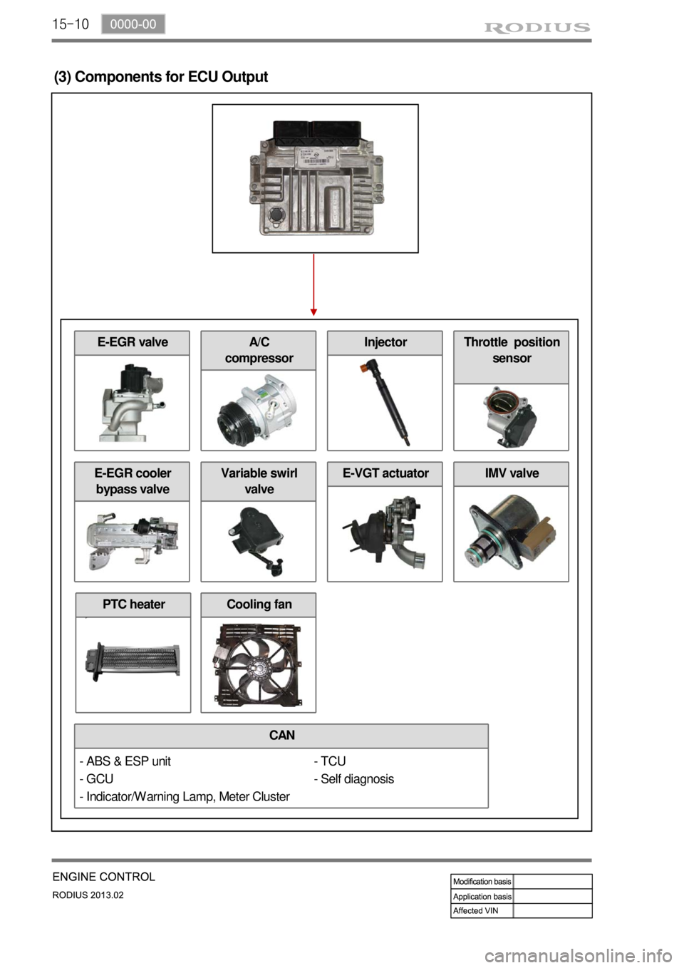
(3) Components for ECU Output
CAN
E-EGR cooler
bypass valve
- TCU
- Self diagnosis
Cooling fan
E-EGR valve
Variable swirl
valveE-VGT actuatorIMV valve
A/C
compressorInjectorThrottle position
sensor
- ABS & ESP unit
- GCU
- Indicator/Warning Lamp, Meter Cluster
PTC heater
Page 339 of 796
15-110000-00
2) ECU Control
(1) Function
a. ECU Function
ECU receives and analyzes signals from various sensors and then modifies those signals into
permissible voltage levels and analyzes to control respective actuators.
ECU microprocessor calculates injection period and injection timing proper for engine piston speed
and crankshaft angle based on input data and stored specific map to control the engine power and
emission gas.
Output signal of the ECU microprocessor drives pressure control valve to control the rail pressure and
activates injector solenoid valve to control the fuel injection period and injection timing; so controls
various actuators in response to engine changes. Auxiliary function of ECU has adopted to reduce
emission gas, improve fuel economy and enhance safety, comforts and conveniences. For example,
there are EGR, booster pressure control, autocruise (export only) and immobilizer and adopted CAN
communication to exchange data among electrical systems (automatic T/M and brake system) in the
vehicle fluently. And Scanner can be used to diagnose vehicle status and defectives.
Operating temperature range of ECU is normally -40 to +85°C and protected from factors like
oil, water and electromagnetism and there should be no mechanical shocks.
To control the fuel volume precisely under repeated injections, high current should be applied instantly
so there is injector drive circuit in the ECU to generate necessary current during injector drive stages.
Current control circuit divides current applying time (injection time) into full-in-current-phase and hold-
current-phase and then the injectors should work very correctly under every working condition.
b. Control Function
Controls by operating stages
To make optimum combustion under every operating stage, ECU should calculate proper injection
volume in each stage by considering various factors.
Starting injection volume control
During initial starting, injecting fuel volume will be calculated by function of temperature and engine
cranking speed. Starting injection continues from when the ignition switch is turned to ignition
position to till the engine reaches to allowable minimum speed.
Driving mode control
If the vehicle runs normally, fuel injection volume will be calculated by accelerator pedal travel and
engine rpm and the drive map will be used to match the drivers inputs with optimum engine power. -
-
-
Page 348 of 796
15-20
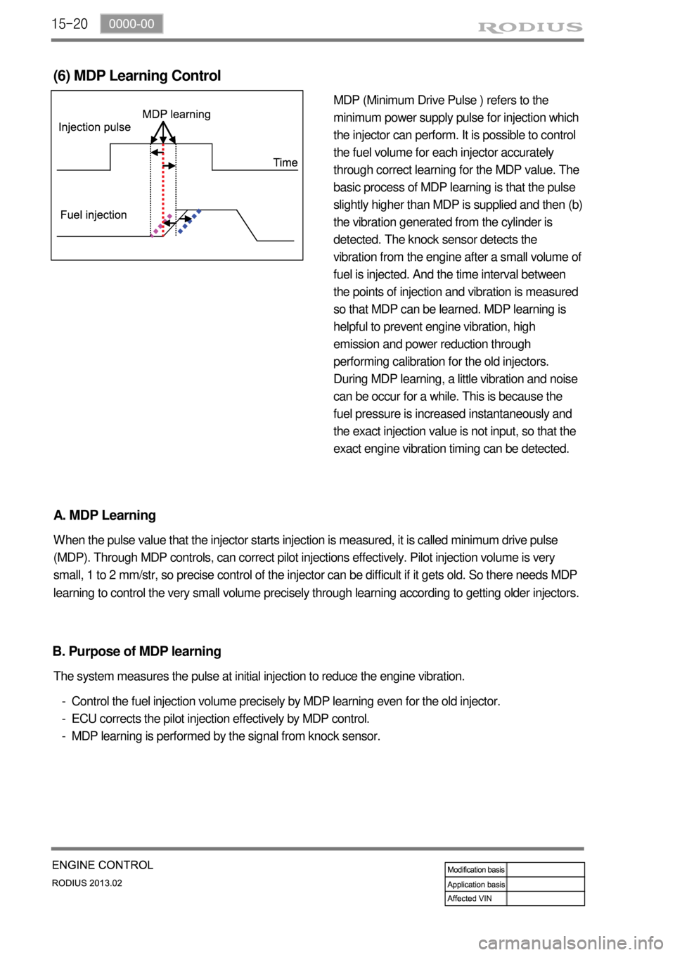
MDP (Minimum Drive Pulse ) refers to the
minimum power supply pulse for injection which
the injector can perform. It is possible to control
the fuel volume for each injector accurately
through correct learning for the MDP value. The
basic process of MDP learning is that the pulse
slightly higher than MDP is supplied and then (b)
the vibration generated from the cylinder is
detected. The knock sensor detects the
vibration from the engine after a small volume of
fuel is injected. And the time interval between
the points of injection and vibration is measured
so that MDP can be learned. MDP learning is
helpful to prevent engine vibration, high
emission and power reduction through
performing calibration for the old injectors.
During MDP learning, a little vibration and noise
can be occur for a while. This is because the
fuel pressure is increased instantaneously and
the exact injection value is not input, so that the
exact engine vibration timing can be detected.
(6) MDP Learning Control
A. MDP Learning
When the pulse value that the injector starts injection is measured, it is called minimum drive pulse
(MDP). Through MDP controls, can correct pilot injections effectively. Pilot injection volume is very
small, 1 to 2 mm/str, so precise control of the injector can be difficult if it gets old. So there needs MDP
learning to control the very small volume precisely through learning according to getting older injectors.
Control the fuel injection volume precisely by MDP learning even for the old injector.
ECU corrects the pilot injection effectively by MDP control.
MDP learning is performed by the signal from knock sensor. -
-
- The system measures the pulse at initial injection to reduce the engine vibration.
B. Purpose of MDP learning
Page 350 of 796
15-22
(7) Knocking Control
A. Resetting the pilot injection
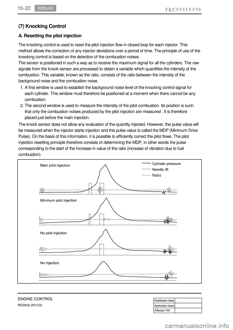
The knocking control is used to reset the pilot injection flow in closed loop for each injector. This
method allows the correction of any injector deviations over a period of time. The principle of use of the
knocking control is based on the detection of the combustion noises.
The sensor is positioned in such a way as to receive the maximum signal for all the cylinders. The raw
signals from the knock sensor are processed to obtain a variable which quantifies the intensity of the
combustion. This variable, known as the ratio, consists of the ratio between the intensity of the
background noise and the combustion noise.
A first window is used to establish the background noise level of the knocking control signal for
each cylinder. This window must therefore be positioned at a moment when there cannot be any
combustion.
The second window is used to measure the intensity of the pilot combustion. Its position is such
that only the combustion noises produced by the pilot injection are measured . It is therefore
placed just before the main injection. 1.
2.
The knock sensor does not allow any evaluation of the quantity injected. However, the pulse value will
be measured when the injector starts injection and this pulse value is called the MDP (Minimum Drive
Pulse). On the basis of this information, it is possible to efficiently correct the pilot flows. The pilot
injection resetting principle therefore consists of determining the MDP, in other words the pulse
corresponding to the start of the increase in value of the ratio (increase of vibration due to fuel
combustion).
Page 351 of 796
15-230000-00
This is done periodically under certain operating conditions. When the resetting is finished, the new
minimum pulse value replaces the value obtained during the previous resetting. The first MDP value is
provided by the C3I. Each resetting then allows the closed loop of the MDP to be updated according to
the deviation of the injector.
B. Detection of leaks in the cylinders
The accelerometer is also used to detect any injector which may have stuck open. The detection
principle is based on monitoring the ratio. If there is a leak in the cylinder, the accumulated fuel self-
ignites as soon as the temperature and pressure conditions are favorable (high engine speed, high
load and small leak).
This combustion is set off at about 20 degrees before TDC and before main injection.
The ratio therefore increases considerably in the detection window. It is this increase which allows the
leaks to be detected. The threshold beyond which a fault is signaled is a percentage of the maximum
possible value of the ratio.
Because of the severity of the recovery process (engine shut-down), the etection must be extremely
robust.
An increase in the ratio can be the consequence of various causes:
Pilot injection too much
Main combustion offset
Fuel leak in the cylinder -
-
-
If the ratio becomes too high, the strategy initially restricts the pilot injection flow and retards the main
injection. If the ratio remains high despite these interventions, this shows that a real leak is present, a
fault is signaled and the engine is shut down.
C. Detection of an accelerometer fault
This strategy permits the detection of a fault in the sensor or in the wiring loom connecting the sensor
to the ECU.
It is based on detection of the combustion. When the engine is idling, the detection window is set too
low for the combustion caused by the main injection. If the ratio increases, this shows that the knock
sensor is working properly, but otherwise a fault is signaled to indicate a sensor failure. The recovery
modes associated with this fault consist of inhibition of the pilot injection and discharge through the
injectors.
Page 352 of 796
15-24
(8) Swirl control
A. Overview
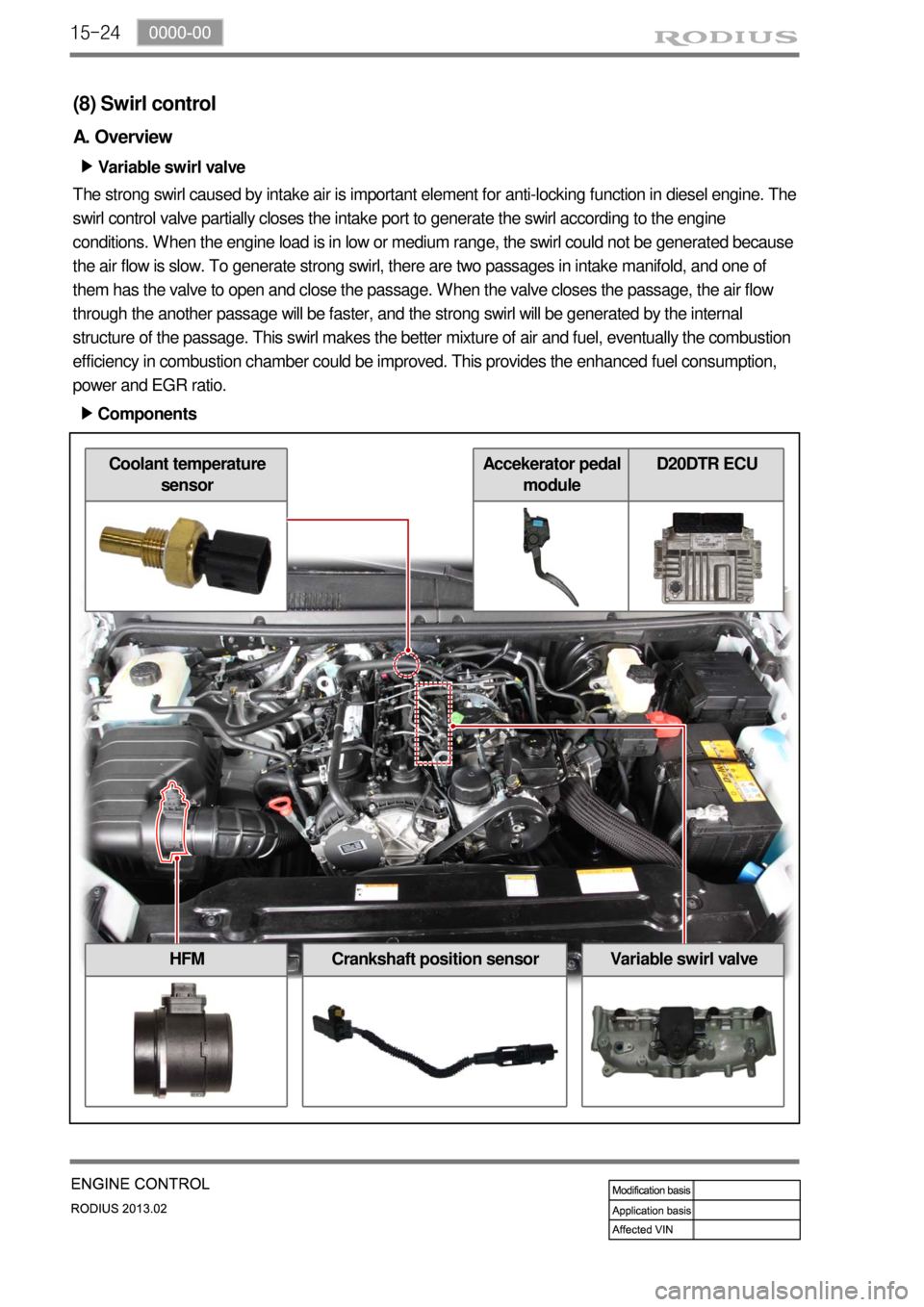
Variable swirl valve ▶
The strong swirl caused by intake air is important element for anti-locking function in diesel engine. The
swirl control valve partially closes the intake port to generate the swirl according to the engine
conditions. When the engine load is in low or medium range, the swirl could not be generated because
the air flow is slow. To generate strong swirl, there are two passages in intake manifold, and one of
them has the valve to open and close the passage. When the valve closes the passage, the air flow
through the another passage will be faster, and the strong swirl will be generated by the internal
structure of the passage. This swirl makes the better mixture of air and fuel, eventually the combustion
efficiency in combustion chamber could be improved. This provides the enhanced fuel consumption,
power and EGR ratio.
Components ▶
HFMCrankshaft position sensorVariable swirl valve
Coolant temperature
sensorAccekerator pedal
moduleD20DTR ECU