eco gauge SUBARU CROSSTREK 2017 1.G Owners Manual
[x] Cancel search | Manufacturer: SUBARU, Model Year: 2017, Model line: CROSSTREK, Model: SUBARU CROSSTREK 2017 1.GPages: 572, PDF Size: 41.52 MB
Page 14 of 572
&Driving vehicles equipped
with navigation system
WARNING
Do not allow the monitor to distract
your attention from driving. Also, do
not operate the controls of the
navigation system while driving.
The loss of attention to driving
could lead to an accident. If you
wish to operate the controls of the
navigation system, first take the
vehicle off the road and stop it in a
safe location.
&Driving with pets
Unrestrained pets can interfere with your
driving and distract your attention from
driving. In a collision or sudden stop,
unrestrained pets or cages can be thrown
around inside the vehicle and hurt you or
your passengers. Besides, the pets can
be hurt under these situations. It is also for
their own safety that pets should be
properly restrained in your vehicle. Re-
strain a pet with a special traveling
harness which can be secured to the rear
seat with a seatbelt or use a pet carrier
which can be secured to the rear seat by
routing a seatbelt through the carrier’shandle. Never restrain pets or pet carriers
in the front passenger’s seat. For further
information, consult your veterinarian,
local animal protection society or pet
shop.
&Tire pressures
Check and, if necessary, adjust the
pressure of each tire (including the spare)
at least once a month and before any long
journey.
Check the tire pressure when the tires are
cold. Use a pressure gauge to adjust the
tire pressures to the values shown on the
tire placard. For detailed information, refer
to“Tires and wheels”F11-21.
WARNING
Driving at high speeds with exces-
sively low tire pressures can cause
the tires to deform severely and to
rapidly become hot. A sharp in-
crease in temperature could cause
tread separation, and destruction of
the tires. The resulting loss of
vehicle control could lead to an
accident.
&Attaching accessories
WARNING
.Do not attach any accessories,
labels or stickers (other than
properly placed inspection stick-
ers) to the windshield. Such
items may obstruct your view.
.If it is necessary to attach an
accessory (such as an electronic
toll collection (ETC) device or
security pass) to the windshield,
consult your SUBARU dealer for
details on the proper location.
8
Page 25 of 572
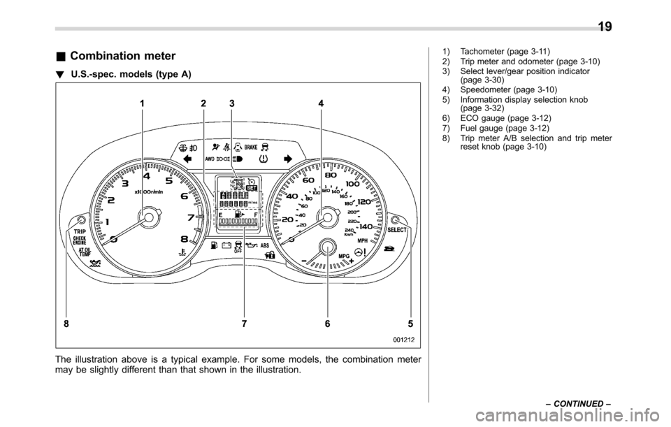
&Combination meter
!U.S.-spec. models (type A)
The illustration above is a typical example. For some models, the combination meter
may be slightly different than that shown in the illustration.
1) Tachometer (page 3-11)
2) Trip meter and odometer (page 3-10)
3) Select lever/gear position indicator
(page 3-30)
4) Speedometer (page 3-10)
5) Information display selection knob
(page 3-32)
6) ECO gauge (page 3-12)
7) Fuel gauge (page 3-12)
8) Trip meter A/B selection and trip meter
reset knob (page 3-10)
–CONTINUED–
19
Page 26 of 572
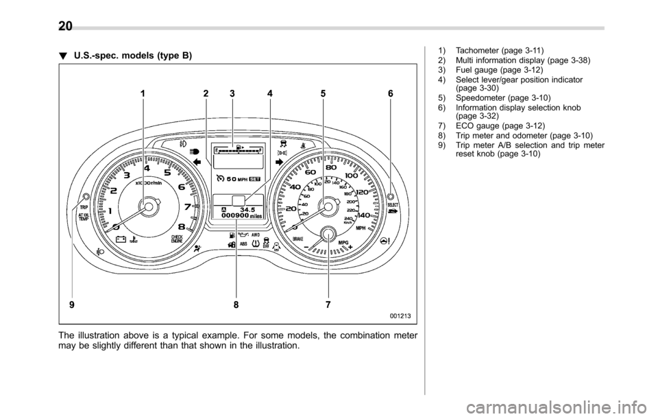
!U.S.-spec. models (type B)
The illustration above is a typical example. For some models, the combination meter
may be slightly different than that shown in the illustration.
1) Tachometer (page 3-11)
2) Multi information display (page 3-38)
3) Fuel gauge (page 3-12)
4) Select lever/gear position indicator
(page 3-30)
5) Speedometer (page 3-10)
6) Information display selection knob
(page 3-32)
7) ECO gauge (page 3-12)
8) Trip meter and odometer (page 3-10)
9) Trip meter A/B selection and trip meter
reset knob (page 3-10)
20
Page 27 of 572
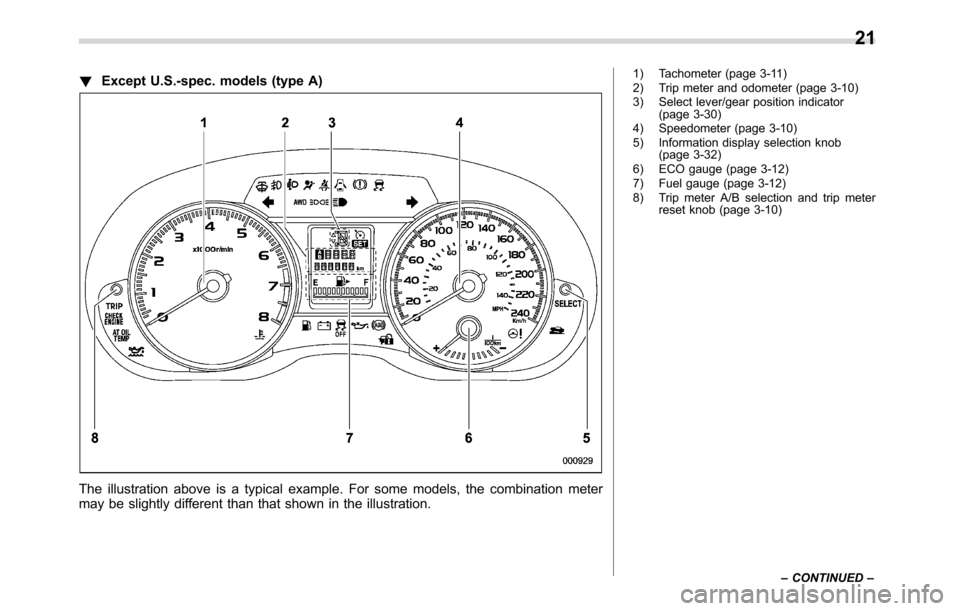
!Except U.S.-spec. models (type A)
The illustration above is a typical example. For some models, the combination meter
may be slightly different than that shown in the illustration.
1) Tachometer (page 3-11)
2) Trip meter and odometer (page 3-10)
3) Select lever/gear position indicator
(page 3-30)
4) Speedometer (page 3-10)
5) Information display selection knob
(page 3-32)
6) ECO gauge (page 3-12)
7) Fuel gauge (page 3-12)
8) Trip meter A/B selection and trip meter
reset knob (page 3-10)
–CONTINUED–
21
Page 28 of 572
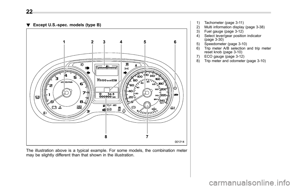
!Except U.S.-spec. models (type B)
The illustration above is a typical example. For some models, the combination meter
may be slightly different than that shown in the illustration.
1) Tachometer (page 3-11)
2) Multi information display (page 3-38)
3) Fuel gauge (page 3-12)
4) Select lever/gear position indicator
(page 3-30)
5) Speedometer (page 3-10)
6) Trip meter A/B selection and trip meter
reset knob (page 3-10)
7) ECO gauge (page 3-12)
8) Trip meter and odometer (page 3-10)
22
Page 139 of 572
Ignition switch (models without“keyless
access with push-button start system”)......... 3-4
LOCK.................................................................. 3-4
ACC.................................................................... 3-5
ON...................................................................... 3-5
START ................................................................ 3-5
Key reminder chime............................................ 3-5
Ignition switch light (if equipped)......................... 3-6
Push-button ignition switch (models with
push-button start system)............................... 3-6
Safety precautions.............................................. 3-6
Operating range for push-button start system...... 3-6
Switching power status....................................... 3-7
When access key does not operate properly........ 3-8
Hazard warning flasher....................................... 3-8
Meters and gauges.............................................. 3-9
Combination meter illumination........................... 3-9
Canceling the function for meter/gauge needle
movement upon turning on the ignition
switch............................................................... 3-9
Speedometer...................................................... 3-10
Odometer........................................................... 3-10
Double trip meter............................................... 3-10
Tachometer........................................................ 3-11
Fuel gauge......................................................... 3-12
ECO gauge (if equipped).................................... 3-12
Warning and indicator lights............................. 3-13
Initial illumination for system check.................... 3-13
Seatbelt warning light and chime........................ 3-14
SRS airbag system warning light........................ 3-15Front passenger’s frontal airbag ON and OFF
indicators........................................................ 3-16
CHECK ENGINE warning light/Malfunction
indicator light.................................................. 3-16
Coolant temperature low indicator light/Coolant
temperature high warning light......................... 3-17
Charge warning light.......................................... 3-18
Oil pressure warning light.................................. 3-18
Engine low oil level warning light....................... 3-18
Windshield washer fluid warning light................ 3-19
AT OIL TEMP warning light (CVT models)........... 3-19
Low tire pressure warning light (U.S.-spec.
models)........................................................... 3-19
ABS warning light.............................................. 3-21
Brake system warning light (red)........................ 3-21
Low fuel warning light....................................... 3-22
Hill start assist warning light/Hill start assist OFF
indicator light.................................................. 3-22
Door open warning light.................................... 3-23
All-Wheel Drive warning light (CVT models) ........ 3-23
Power steering warning light.............................. 3-23
Vehicle Dynamics Control warning light/Vehicle
Dynamics Control operation indicator light ....... 3-24
Vehicle Dynamics Control OFF indicator light..... 3-25
Warning chimes and warning indicator of the
keyless access with push-button start system (if
equipped)........................................................ 3-25
Security indicator light....................................... 3-30
Select lever/gear position indicator (CVT
models)........................................................... 3-30
Turn signal indicator lights................................. 3-31
High beam indicator light................................... 3-31
Instruments and controls
3
Page 147 of 572
Meters and gauges
NOTE
Some of the meters and gauges on the
combination meter use liquid-crystal
displays. You will find their indications
hard to see if you wear polarized
glasses.
&Combination meter illumina-
tion
When the ignition switch is turned to the
“ON”position, various parts of the combi-
nation meter will illuminate in the following
sequence.
1. Warning lights, indicator lights, meter
needles, gauge needles and liquid crystal
display illuminate.
2. Meter and gauge indications each
show MAX position.
3. Meter and gauge indications each
show MIN position.
4. Regular illumination (for driving) be-
gins.
&Canceling the function for
meter/gauge needle move-
ment upon turning on the
ignition switch
It is possible to activate or deactivate the
movement of the meter needles and
gauge needles that takes place when the
ignition switch is turned to the“ON”
position.
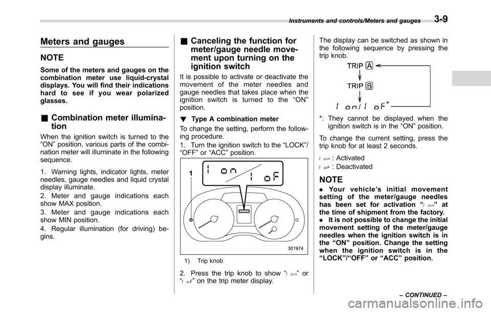
!Type A combination meter
To change the setting, perform the follow-
ing procedure.
1. Turn the ignition switch to the“LOCK”/
“OFF”or“ACC”position.
1) Trip knob
2. Press the trip knob to show“”or
“”on the trip meter display.The display can be switched as shown in
the following sequence by pressing the
trip knob.
*: They cannot be displayed when the
ignition switch is in the“ON”position.
To change the current setting, press the
trip knob for at least 2 seconds.
: Activated
: Deactivated
NOTE
.Your vehicle’s initial movement
setting of the meter/gauge needles
has been set for activation“
”at
the time of shipment from the factory.
.It is not possible to change the initial
movement setting of the meter/gauge
needles when the ignition switch is in
the“ON”position. Change the setting
when the ignition switch is in the
“LOCK”/“OFF”or“ACC”position.
Instruments and controls/Meters and gauges
–CONTINUED–3-9
Page 148 of 572
Instruments and controls/Meters and gauges
!Type B combination meter
Perform the procedures described in
“Gauge Initial Movement”F3-41.
&Speedometer
The speedometer shows the vehicle
speed.
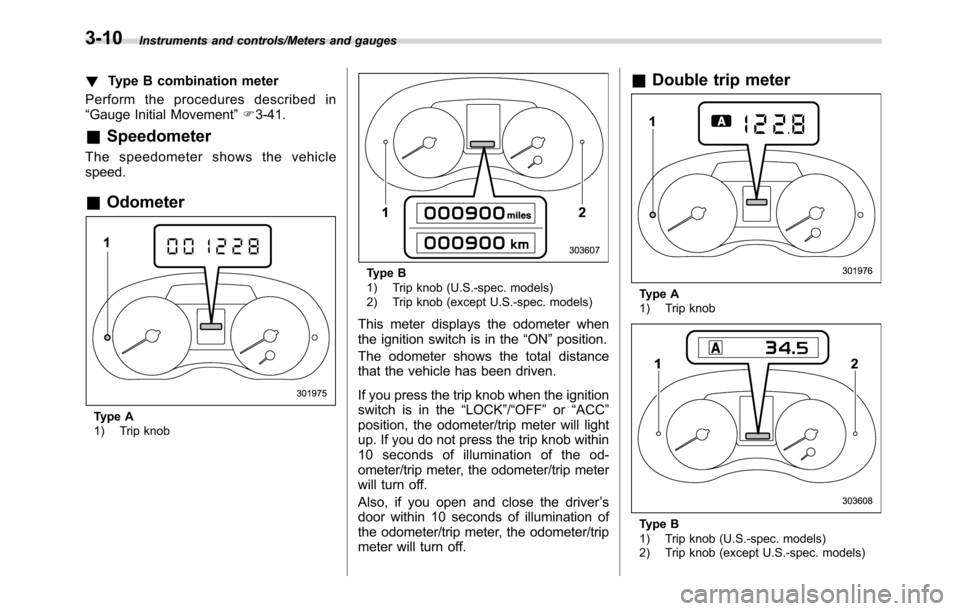
&Odometer
Type A
1) Trip knob
Type B
1) Trip knob (U.S.-spec. models)
2) Trip knob (except U.S.-spec. models)
This meter displays the odometer when
the ignition switch is in the“ON”position.
The odometer shows the total distance
that the vehicle has been driven.
If you press the trip knob when the ignition
switch is in the“LOCK”/“OFF”or“ACC”
position, the odometer/trip meter will light
up. If you do not press the trip knob within
10 seconds of illumination of the od-
ometer/trip meter, the odometer/trip meter
will turn off.
Also, if you open and close the driver’s
door within 10 seconds of illumination of
the odometer/trip meter, the odometer/trip
meter will turn off.
&Double trip meter
Type A
1) Trip knob
Type B
1) Trip knob (U.S.-spec. models)
2) Trip knob (except U.S.-spec. models)
3-10
Page 149 of 572
This meter displays the two trip meters
when the ignition switch is in the“ON”
position.
The trip meter shows the distance that the
vehicle has been driven since you last set
it to zero.
If you press the trip knob when the ignition
switch is in the“LOCK”/“OFF”or“ACC”
position, the odometer/trip meter will light
up. It is possible to switch between the A
trip meter and B trip meter indications
while the odometer/trip meter is lit up. If
you do not press the trip knob within 10
seconds of illumination of the odometer/
trip meter, the odometer/trip meter will turn
off.
Also, if you open and close the driver’s
door within 10 seconds of illumination of
the odometer/trip meter, the odometer/trip
meter will turn off.
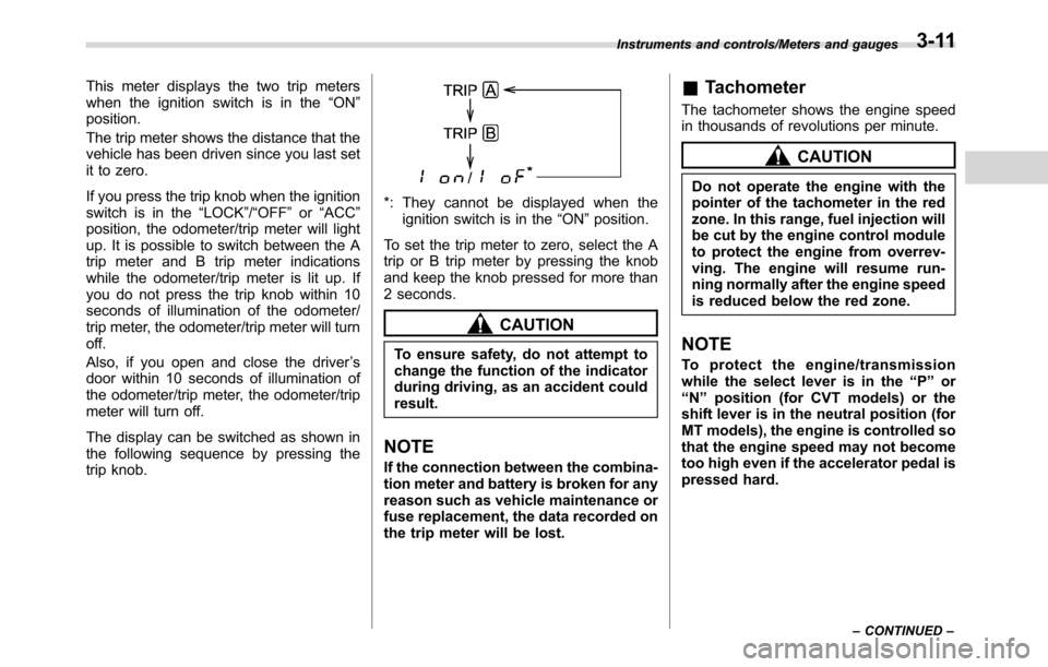
The display can be switched as shown in
the following sequence by pressing the
trip knob.
*: They cannot be displayed when the
ignition switch is in the“ON”position.
To set the trip meter to zero, select the A
trip or B trip meter by pressing the knob
and keep the knob pressed for more than
2 seconds.
CAUTION
To ensure safety, do not attempt to
change the function of the indicator
during driving, as an accident could
result.
NOTE
If the connection between the combina-
tion meter and battery is broken for any
reason such as vehicle maintenance or
fuse replacement, the data recorded on
the trip meter will be lost.
&Tachometer
The tachometer shows the engine speed
in thousands of revolutions per minute.
CAUTION
Do not operate the engine with the
pointer of the tachometer in the red
zone. In this range, fuel injection will
be cut by the engine control module
to protect the engine from overrev-
ving. The engine will resume run-
ning normally after the engine speed
is reduced below the red zone.
NOTE
To protect the engine/transmission
while the select lever is in the“P”or
“N”position (for CVT models) or the
shift lever is in the neutral position (for
MT models), the engine is controlled so
that the engine speed may not become
too high even if the accelerator pedal is
pressed hard.
Instruments and controls/Meters and gauges
–CONTINUED–3-11
Page 150 of 572
Instruments and controls/Meters and gauges
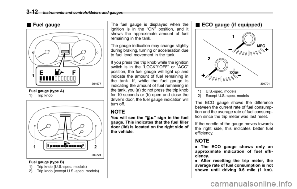
&Fuel gauge
Fuel gauge (type A)
1) Trip knob
Fuel gauge (type B)
1) Trip knob (U.S.-spec. models)
2) Trip knob (except U.S.-spec. models)
The fuel gauge is displayed when the
ignition is in the“ON”position, and it
shows the approximate amount of fuel
remaining in the tank.
The gauge indication may change slightly
during braking, turning or acceleration due
to fuel level movement in the tank.
If you press the trip knob while the ignition
switch is in the“LOCK”/“OFF”or“ACC”
position, the fuel gauge will light up and
indicate the amount of fuel remaining in
the tank. If, while the fuel gauge is
indicating the amount of fuel remaining in
the tank, you (a) do not press the trip knob
for 10 seconds or (b) open and close the
driver’s door, the fuel gauge indication will
turn off.
NOTE
You will see the“”sign in the fuel
gauge. This indicates that the fuel filler
door (lid) is located on the right side of
the vehicle.
&ECO gauge (if equipped)
1) U.S.-spec. models
2) Except U.S.-spec. models
The ECO gauge shows the difference
between the current rate of fuel consump-
tion and the average rate of fuel consump-
tion since the trip meter was last reset.
If the needle of the gauge moves towards
the right side, this indicates better fuel
efficiency.
NOTE
.The ECO gauge shows only an
approximate indication of fuel effi-
ciency.
.After resetting the trip meter, the
average rate of fuel consumption is not
shown until driving 0.6 mile (1 km).
3-12