tires SUBARU CROSSTREK 2017 1.G Owners Manual
[x] Cancel search | Manufacturer: SUBARU, Model Year: 2017, Model line: CROSSTREK, Model: SUBARU CROSSTREK 2017 1.GPages: 572, PDF Size: 41.52 MB
Page 14 of 572
&Driving vehicles equipped
with navigation system
WARNING
Do not allow the monitor to distract
your attention from driving. Also, do
not operate the controls of the
navigation system while driving.
The loss of attention to driving
could lead to an accident. If you
wish to operate the controls of the
navigation system, first take the
vehicle off the road and stop it in a
safe location.
&Driving with pets
Unrestrained pets can interfere with your
driving and distract your attention from
driving. In a collision or sudden stop,
unrestrained pets or cages can be thrown
around inside the vehicle and hurt you or
your passengers. Besides, the pets can
be hurt under these situations. It is also for
their own safety that pets should be
properly restrained in your vehicle. Re-
strain a pet with a special traveling
harness which can be secured to the rear
seat with a seatbelt or use a pet carrier
which can be secured to the rear seat by
routing a seatbelt through the carrier’shandle. Never restrain pets or pet carriers
in the front passenger’s seat. For further
information, consult your veterinarian,
local animal protection society or pet
shop.
&Tire pressures
Check and, if necessary, adjust the
pressure of each tire (including the spare)
at least once a month and before any long
journey.
Check the tire pressure when the tires are
cold. Use a pressure gauge to adjust the
tire pressures to the values shown on the
tire placard. For detailed information, refer
to“Tires and wheels”F11-21.
WARNING
Driving at high speeds with exces-
sively low tire pressures can cause
the tires to deform severely and to
rapidly become hot. A sharp in-
crease in temperature could cause
tread separation, and destruction of
the tires. The resulting loss of
vehicle control could lead to an
accident.
&Attaching accessories
WARNING
.Do not attach any accessories,
labels or stickers (other than
properly placed inspection stick-
ers) to the windshield. Such
items may obstruct your view.
.If it is necessary to attach an
accessory (such as an electronic
toll collection (ETC) device or
security pass) to the windshield,
consult your SUBARU dealer for
details on the proper location.
8
Page 18 of 572
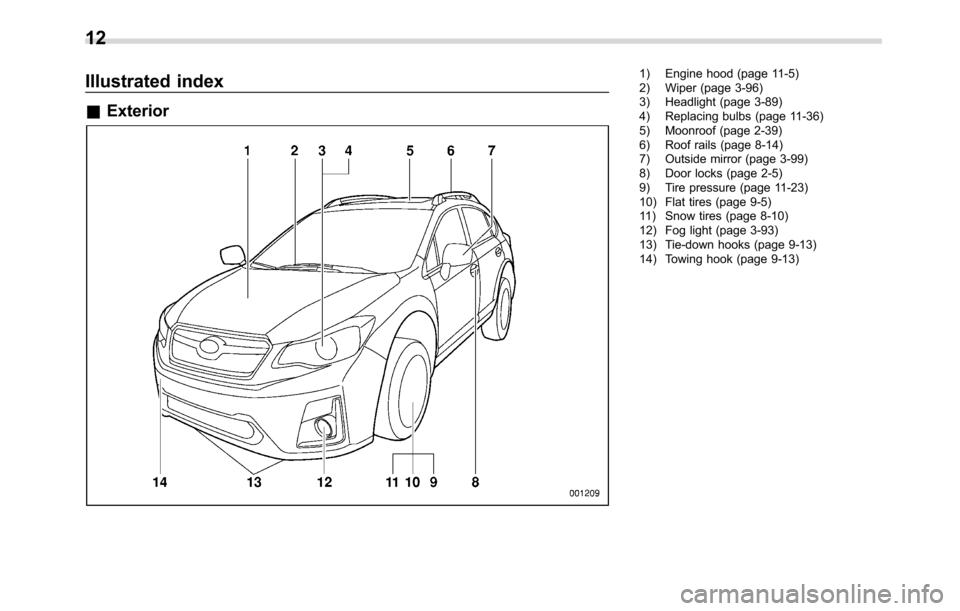
Illustrated index
&Exterior
1) Engine hood (page 11-5)
2) Wiper (page 3-96)
3) Headlight (page 3-89)
4) Replacing bulbs (page 11-36)
5) Moonroof (page 2-39)
6) Roof rails (page 8-14)
7) Outside mirror (page 3-99)
8) Door locks (page 2-5)
9) Tire pressure (page 11-23)
10) Flat tires (page 9-5)
11) Snow tires (page 8-10)
12) Fog light (page 3-93)
13) Tie-down hooks (page 9-13)
14) Towing hook (page 9-13)
12
Page 56 of 572
Seat, seatbelt and SRS airbags/Child restraint systems
of the seatbelt pretensioner, con-
sult your nearest SUBARU deal-
er.
CAUTION
The sensors and SRS airbag control
module are located in the following
locations.
.Front sub sensors: on both the
right and left side at the front of
the vehicle
.Front door impact sensors: on
both front doors
.Satellite safing sensor: under the
rear center seat
.SRS airbag control module (in-
cluding the impact sensors and
rollover sensor): under the cen-
ter of the instrument panel
If you need service or repair in those
areas or near the front seatbelt
retractors, have the work performed
by your authorized SUBARU dealer.
NOTE
If the front or side part of the vehicle is
damaged in an accident to the extent
that the seatbelt pretensioner does notoperate, contact your SUBARU dealer
as soon as possible.
&Precautions against vehicle
modification
Always consult your SUBARU dealer if
you want to install any accessory parts to
your vehicle.
CAUTION
Do not perform any of the following
modifications. Such modifications
can interfere with proper operation
of the seatbelt pretensioners.
.Attachment of any equipment
(bush bar, winches, snow plow,
skid plate, etc.) other than genu-
ine SUBARU accessory parts to
the front end.
.Modification of the suspension
system or front end structure.
.Installation of a tire of different
size and construction from the
tires specified on the vehicle
placard attached to the driver’s
door pillar or specified for indivi-
dual vehicle models in this Own-
er’s Manual.
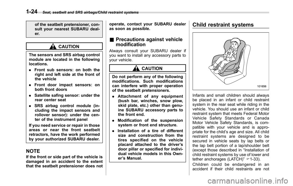
Child restraint systems
Infants and small children should always
be placed in an infant or child restraint
system in the rear seat while riding in the
vehicle. You should use an infant or child
restraint system that meets Federal Motor
Vehicle Safety Standards or Canada
Motor Vehicle Safety Standards, is com-
patible with your vehicle and is appro-
priate for the child’s age and size. All child
restraint systems are designed to be
secured in vehicle seats by lap belts or
the lap belt portion of a lap/shoulder belt
(except those described in“Installation of
child restraint systems by use of lower and
tether anchorages (LATCH)”F1-33).
Children could be endangered in an
accident if their child restraints are not
1-24
Page 91 of 572
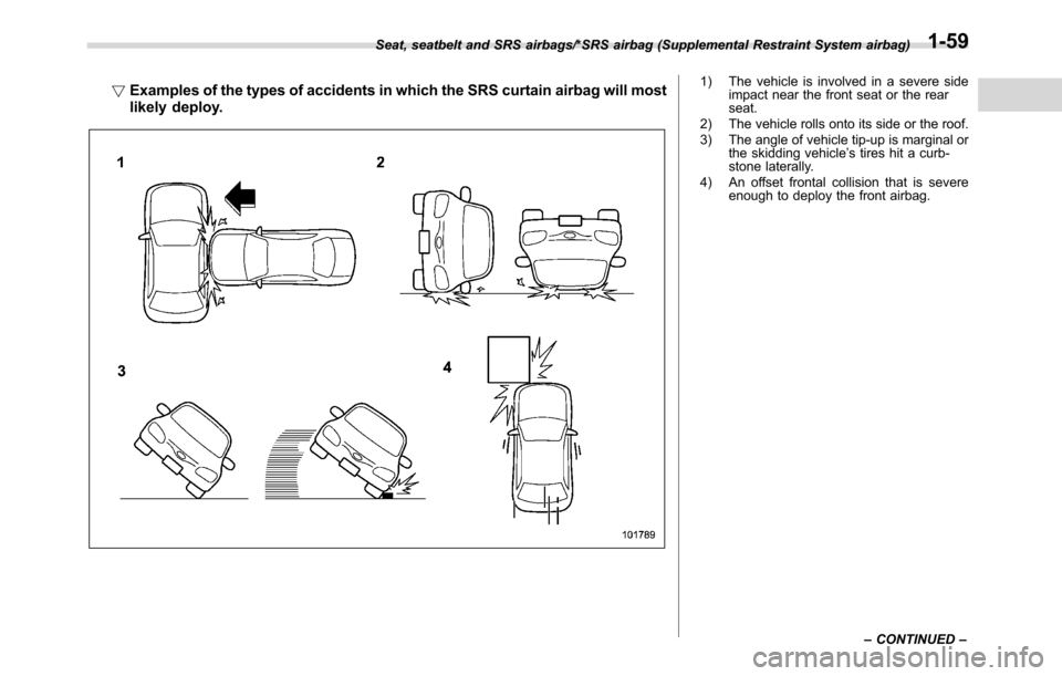
!Examples of the types of accidents in which the SRS curtain airbag will most
likely deploy.1) The vehicle is involved in a severe side
impact near the front seat or the rear
seat.
2) The vehicle rolls onto its side or the roof.
3) The angle of vehicle tip-up is marginal or
the skidding vehicle’s tires hit a curb-
stone laterally.
4) An offset frontal collision that is severe
enough to deploy the front airbag. Seat, seatbelt and SRS airbags/*SRS airbag (Supplemental Restraint System airbag)
–CONTINUED–
1-59
Page 98 of 572
Seat, seatbelt and SRS airbags/*SRS airbag (Supplemental Restraint System airbag)
&Precautions against vehicle
modification
WARNING
To avoid accidental activation of the
system or rendering the system
inoperative, which may result in
serious injury, no modifications
should be made to any components
or wiring of the SRS airbag system.
This includes following modifica-
tions.
.Installation of custom steering
wheels
.Attachment of additional trim
materials to the dashboard
.Installation of custom seats
.Replacement of seat fabric or
leather
.Installation of additional fabric or
leather on the front seat
.Attachment of a hands-free mi-
crophone or any other accessory
to a front pillar, a center pillar, a
rear pillar, the windshield, a side
window, an assist grip, or any
other cabin surface that would be
near a deploying SRS curtain
airbag..Installation of additional electri-
cal/electronic equipment such as
a mobile two-way radio on or
near the SRS airbag system
components and/or wiring is not
advisable. This could interfere
with proper operation of the
SRS airbag system.
CAUTION
Do not perform any of the following
modifications. Such modifications
can interfere with proper operation
of the SRS airbag system.
.Attachment of any equipment
(bush bar, winches, snow plow,
skid plate, etc.) other than genu-
ine SUBARU accessory parts to
the front end.
.Modification of the suspension
system or front end structure.
.Installation of a tire of different
size and construction from the
tires specified on the vehicle
placard attached to the driver’s
door pillar or specified for indivi-
dual vehicle models in this Own-
er’s Manual.
.Attachment of any equipment
(side steps or side sill protectors,etc.) other than genuine SUBARU
accessory parts to the side body.
Always consult your SUBARU dealer if
you want to install any accessory parts on
your vehicle.
1-66
Page 157 of 572
NOTE
.After replacing or adding the engine
oil, if the engine oil level is within the
normal range when restarting the en-
gine on a level surface, the warning
light will turn off.
.The warning light may illuminate
temporarily in the following conditions
because a low oil level may be detected
as a result of significant oil movement
in the engine.
–when the vehicle is considerably
inclined on an uphill or steep slope
–when the vehicle has continu-
ously accelerated and decelerated
–when the vehicle is continuously
turned
–when the vehicle is driven on a
road that alternates continuously
between uphill and downhill
&Windshield washer
fluid warning light
This light illuminates when the fluid level in
the windshield washer fluid tank de-
creases to the lower limit (approximately
1.1 US qt, 1.0 liter, 0.9 Imp qt).
&AT OIL TEMP warning
light (CVT models)
If this light illuminates when the engine is
running, it may indicate that the transmis-
sion fluid temperature is too hot.
If the light illuminates while driving, im-
mediately stop the vehicle in a safe place
and let the engine idle until the warning
light turns off.
!Transmission control system warn-
ing
If the“AT OIL TEMP”warning light flashes
after the engine has started, it may
indicate that the transmission control
system is not working properly. Contact
your nearest SUBARU dealer for service
immediately.
&Low tire pressure
warning light (U.S.-spec.
models)
When the ignition switch is turned to the
“ON”position, the low tire pressure warn-
ing light will illuminate for approximately 2
seconds to check that the tire pressure
monitoring system (TPMS) is functioning
properly. If there is no problem and all tires
are properly inflated, the light will turn off.
Each tire, including the spare (if provided),should be checked monthly when cold
and inflated to the inflation pressure
recommended by the vehicle manufac-
turer on the vehicle placard or tire inflation
pressure label. (If your vehicle has tires of
a different size than the size indicated on
the vehicle placard or tire inflation pres-
sure label, you should determine the
proper tire inflation pressure for those
tires.)
As an added safety feature, your vehicle
has been equipped with a tire pressure
monitoring system (TPMS) that illuminates
a low tire pressure telltale when one or
more of your tires is significantly under-
inflated. Accordingly, when the low tire
pressure telltale illuminates, you should
stop and check your tires as soon as
possible, and inflate them to the proper
pressure. Driving on a significantly under-
inflated tire causes the tire to overheat and
can lead to tire failure. Under-inflation also
reduces fuel efficiency and tire tread life,
and may affect the vehicle’s handling and
stopping ability.
Please note that the TPMS is not a
substitute for proper tire maintenance,
and it is the driver’s responsibility to
maintain correct tire pressure, even if
under-inflation has not reached the level
to trigger illumination of the TPMS low tire
pressure telltale.
Instruments and controls/Warning and indicator lights
–CONTINUED–3-19
Page 158 of 572
Instruments and controls/Warning and indicator lights
Your vehicle has also been equipped with
a TPMS malfunction indicator to indicate
when the system is not operating properly.
The TPMS malfunction indicator is com-
bined with the low tire pressure telltale.
When the system detects a malfunction,
the telltale will flash for approximately one
minute and then remain continuously
illuminated. This sequence will continue
upon subsequent vehicle start-ups as long
as the malfunction exists. When the
malfunction indicator is illuminated, the
system may not be able to detect or signal
low tire pressure as intended. TPMS
malfunctions may occur for a variety of
reasons, including the installation of re-
placement or alternate tires or wheels on
the vehicle that prevent the TPMS from
functioning properly. Always check the
TPMS malfunction telltale after replacing
one or more tires or wheels on your
vehicle to ensure that the replacement or
alternate tires and wheels allow the TPMS
to continue to function properly.
Should the warning light illuminate stea-
dily after blinking for approximately one
minute, have the system inspected by
your nearest SUBARU dealer as soon as
possible.WARNING
If this light does not illuminate
briefly after the ignition switch is
turned ON or the light illuminates
steadily after blinking for approxi-
mately one minute, you should have
your Tire Pressure Monitoring Sys-
tem checked at a SUBARU dealer as
soon as possible.
If this light illuminates while driving,
never brake suddenly. Instead, per-
form the following procedure. Other-
wise an accident involving serious
vehicle damage and serious perso-
nal injury could occur.
1) Keep driving straight ahead while
gradually reducing speed.
2) Slowly pull off the road to a safe
place.
If this light still illuminates while
driving after adjusting the tire pres-
sure, a tire may have significant
damage and a fast leak that causes
the tire to lose air rapidly. If you have
a flat tire, replace it with a spare tire
as soon as possible.
When a spare tire is mounted or a
wheel rim is replaced without the
original pressure sensor/transmitter
being transferred, the Low tire pres-sure warning light will illuminate
steadily after blinking for approxi-
mately one minute. This indicates
the TPMS is unable to monitor all
four road wheels. Contact your
SUBARU dealer as soon as possible
for tire and sensor replacement and/
or system resetting.
If the light illuminates steadily after
blinking for approximately one min-
ute, promptly contact a SUBARU
dealer to have the system inspected.
CAUTION
The tire pressure monitoring system
is NOT a substitute for manually
checking tire pressure. The tire
pressure should be checked peri-
odically (at least monthly) using a
tire gauge. After any change to tire
pressure(s), the tire pressure mon-
itoring system will not re-check tire
inflation pressures until the vehicle
is first driven more than 20 mph (32
km/h). After adjusting the tire pres-
sures, increase the vehicle speed to
at least 20 mph (32 km/h) to start the
TPMS re-checking of the tire infla-
tion pressures. If the tire pressures
are now above the severe low
pressure threshold, the low tire
3-20
Page 159 of 572
pressure warning light should turn
off a few minutes later. Therefore, be
sure to install the specified size for
the front and rear tires.
&ABS warning light
CAUTION
.If any of the following conditions
occur, we recommend that you
have the ABS repaired at the first
available opportunity by your
SUBARU dealer.
–The warning light does not
illuminate when the ignition
switch is turned to the“ON”
position.
–The warning light illuminates
when the ignition switch is
turned to the“ON”position,
but it does not turn off even
when the vehicle speed ex-
ceeds approximately 25 mph
(40 km/h).
–The warning light illuminates
during driving.
.When the warning light is on (and
the brake system warning light is
off), the ABS function shuts
down. However, the conventionalbrake system continues to oper-
ate normally.
The ABS warning light illuminates to-
gether with the brake system warning light
if the EBD system malfunctions. For
further details of the EBD system mal-
function warning, refer to“Electronic
Brake Force Distribution (EBD) system
warning”F3-22.NOTE
If the warning light behavior is as
described in the following conditions,
the ABS may be considered normal.
.The warning light illuminates when
the ignition switch is turned to the
“ON”position and turns off approxi-
mately 2 seconds after the engine has
started.
.The warning light illuminates right
after the engine is started but turns off
immediately, remaining off.
.The warning light remains illumi-
nated after the engine has been started,
but it turns off when the vehicle speed
reaches approximately 25 mph (40
km/h).
.The warning light illuminates during
driving, but it turns off immediately and
remains off.
When driving with an insufficient batteryvoltage such as when the engine is jump
started, the ABS warning light may illumi-
nate. This is due to the low battery voltage
and does not indicate a malfunction.
When the battery becomes fully charged,
the light will turn off.
&Brake system
warning light (red)
The light illuminates with the parking
brake applied while the ignition switch is
in the“ON”position. It turns off when the
parking brake is fully released.
WARNING
.Driving with the brake system
warning light on is dangerous.
This indicates your brake system
may not be working properly. If
the light remains illuminated,
have the brakes inspected by a
SUBARU dealer immediately.
.If at all in doubt about whether
the brakes are operating prop-
erly, do not drive the vehicle.
Have your vehicle towed to the
nearest SUBARU dealer for re-
pair.
The brake system warning light has the
following functions.
Instruments and controls/Warning and indicator lights
–CONTINUED–3-21
Page 161 of 572
WARNING
When the Hill start assist warning
light illuminates, have the vehicle
inspected at an authorized SUBARU
dealer.
!Hill start assist OFF indicator light
While the Hill start assist system is
deactivated, the Hill start assist OFF
indicator light illuminates continuously to
inform the driver that the Hill start assist
system is not operational.
&Door open warning
light
The warning light illuminates if any door
(including the rear gate) is not fully closed.
This function is effective even if the
ignition switch is in the“LOCK”/“OFF”or
“ACC”position, or the key is removed from
the ignition switch.
Always make sure this light is not illumi-
nated before you start to drive.
&All-Wheel Drive warn-
ing light (CVT models)
This light blinks if the vehicle is driven with
tires of differing diameters fitted on the
wheels or with an excessively low airpressure in any of the tires.
WARNING
If the AWD warning light flashes,
promptly park in a safe location then
check whether all four tires are the
same diameter and whether any of
the tires has a puncture or has lost
air pressure for some other reason.
Continuing to drive with the AWD
warning light flashing can lead to
powertrain damage.
&Power steering warn-
ing light
This warning light illuminates when the
ignition switch is turned to the“ON”
position and turns off after the engine
has started. This indicates that the warn-
ing system is working properly.
While the engine is running, this warning
light illuminates when a malfunction has
been detected in the electric power steer-
ing system.
CAUTION
When the power steering warning
light is illuminated, there may be
more resistance when the steeringwheel is operated. Drive carefully to
the nearest SUBARU dealer and
have the vehicle inspected immedi-
ately.
NOTE
If the steering wheel is operated in the
following ways, the power steering
control system may temporarily limit
the power assist in order to prevent the
system components, such as the con-
trol computer and drive motor, from
overheating.
.The steering wheel is operated fre-
quently and turned sharply while the
vehicle is maneuvered at extremely low
speeds, such as while frequently turn-
ing the steering wheel during parallel
parking.
.The steering wheel remains in the
fully turned position for a long period
of time.
At this time, there will be more resis-
tance when steering. However this is
not a malfunction. Normal steering
force will be restored after the steering
wheel is not operated for a while and
the power steering control system has
an opportunity to cool down. However,
if the power steering is operated in a
non-standard way which causes power
Instruments and controls/Warning and indicator lights
–CONTINUED–3-23
Page 183 of 572
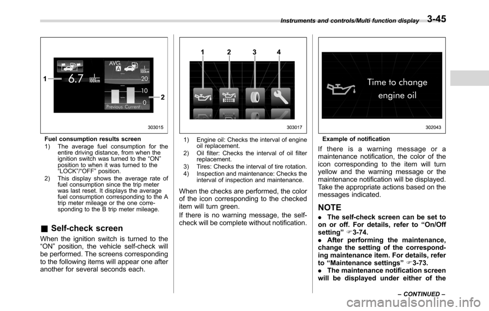
Fuel consumption results screen
1) The average fuel consumption for the
entire driving distance, from when the
ignition switch was turned to the“ON”
position to when it was turned to the
“LOCK”/“OFF”position.
2) This display shows the average rate of
fuel consumption since the trip meter
was last reset. It displays the average
fuel consumption corresponding to the A
trip meter mileage or the one corre-
sponding to the B trip meter mileage.
&Self-check screen
When the ignition switch is turned to the
“ON”position, the vehicle self-check will
be performed. The screens corresponding
to the following items will appear one after
another for several seconds each.
1) Engine oil: Checks the interval of engine
oil replacement.
2) Oil filter: Checks the interval of oil filter
replacement.
3) Tires: Checks the interval of tire rotation.
4) Inspection and maintenance: Checks the
interval of inspection and maintenance.
When the checks are performed, the color
of the icon corresponding to the checked
item will turn green.
If there is no warning message, the self-
check will be complete without notification.
Example of notification
If there is a warning message or a
maintenance notification, the color of the
icon corresponding to the item will turn
yellow and the warning message or the
maintenance notification will be displayed.
Take the appropriate actions based on the
messages indicated.
NOTE
.The self-check screen can be set to
on or off. For details, refer to“On/Off
setting”F3-74.
.After performing the maintenance,
change the setting of the correspond-
ing maintenance item. For details, refer
to“Maintenance settings”F3-73.
.The maintenance notification screen
will be displayed under either of the
Instruments and controls/Multi function display
–CONTINUED–3-45