service SUBARU FORESTER 1999 Service Repair Manual
[x] Cancel search | Manufacturer: SUBARU, Model Year: 1999, Model line: FORESTER, Model: SUBARU FORESTER 1999Pages: 345, PDF Size: 5.6 MB
Page 82 of 345
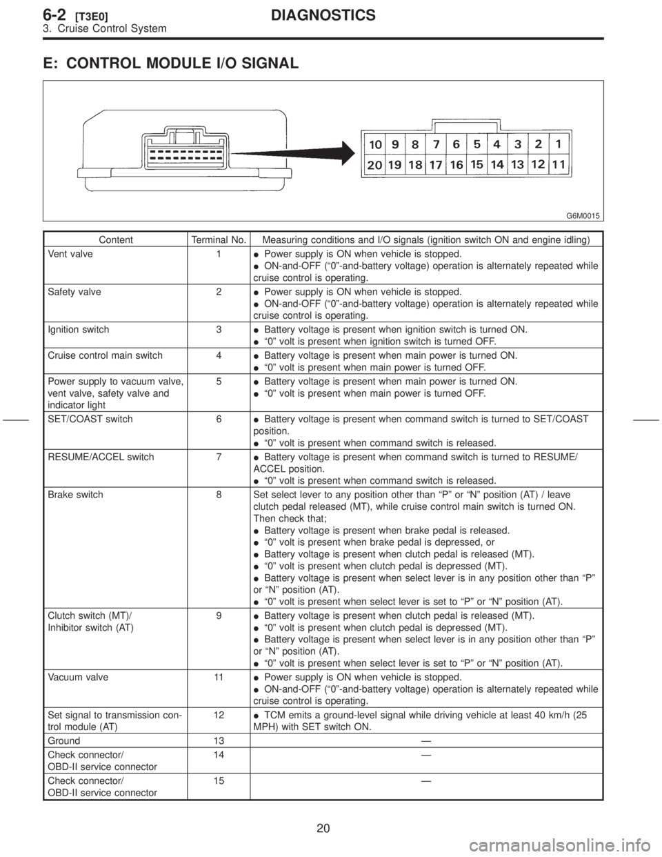
E: CONTROL MODULE I/O SIGNAL
G6M0015
Content Terminal No. Measuring conditions and I/O signals (ignition switch ON and engine idling)
Vent valve 1IPower supply is ON when vehicle is stopped.
ION-and-OFF (ª0º-and-battery voltage) operation is alternately repeated while
cruise control is operating.
Safety valve 2IPower supply is ON when vehicle is stopped.
ION-and-OFF (ª0º-and-battery voltage) operation is alternately repeated while
cruise control is operating.
Ignition switch 3IBattery voltage is present when ignition switch is turned ON.
Iª0º volt is present when ignition switch is turned OFF.
Cruise control main switch 4IBattery voltage is present when main power is turned ON.
Iª0º volt is present when main power is turned OFF.
Power supply to vacuum valve,
vent valve, safety valve and
indicator light5IBattery voltage is present when main power is turned ON.
Iª0º volt is present when main power is turned OFF.
SET/COAST switch 6IBattery voltage is present when command switch is turned to SET/COAST
position.
Iª0º volt is present when command switch is released.
RESUME/ACCEL switch 7IBattery voltage is present when command switch is turned to RESUME/
ACCEL position.
Iª0º volt is present when command switch is released.
Brake switch 8 Set select lever to any position other than ªPº or ªNº position (AT) / leave
clutch pedal released (MT), while cruise control main switch is turned ON.
Then check that;
IBattery voltage is present when brake pedal is released.
Iª0º volt is present when brake pedal is depressed, or
IBattery voltage is present when clutch pedal is released (MT).
Iª0º volt is present when clutch pedal is depressed (MT).
IBattery voltage is present when select lever is in any position other than ªPº
or ªNº position (AT).
Iª0º volt is present when select lever is set to ªPº or ªNº position (AT).
Clutch switch (MT)/
Inhibitor switch (AT)9IBattery voltage is present when clutch pedal is released (MT).
Iª0º volt is present when clutch pedal is depressed (MT).
IBattery voltage is present when select lever is in any position other than ªPº
or ªNº position (AT).
Iª0º volt is present when select lever is set to ªPº or ªNº position (AT).
Vacuum valve 11IPower supply is ON when vehicle is stopped.
ION-and-OFF (ª0º-and-battery voltage) operation is alternately repeated while
cruise control is operating.
Set signal to transmission con-
trol module (AT)12ITCM emits a ground-level signal while driving vehicle at least 40 km/h (25
MPH) with SET switch ON.
Ground 13 Ð
Check connector/
OBD-II service connector14 Ð
Check connector/
OBD-II service connector15 Ð
20
6-2[T3E0]DIAGNOSTICS
3. Cruise Control System
Page 157 of 345
1. Precaution
A: SUPPLEMENTAL RESTRAINT
SYSTEM ªAIRBAGº
Airbag system wiring harness is routed on and
along body panels.
CAUTION:
IAll airbag system wiring harness and con-
nectors are yellow. Do not use electrical test
equipment on these circuit.
IBe careful not to damage airbag system wir-
ing harness when repairing the body panel.
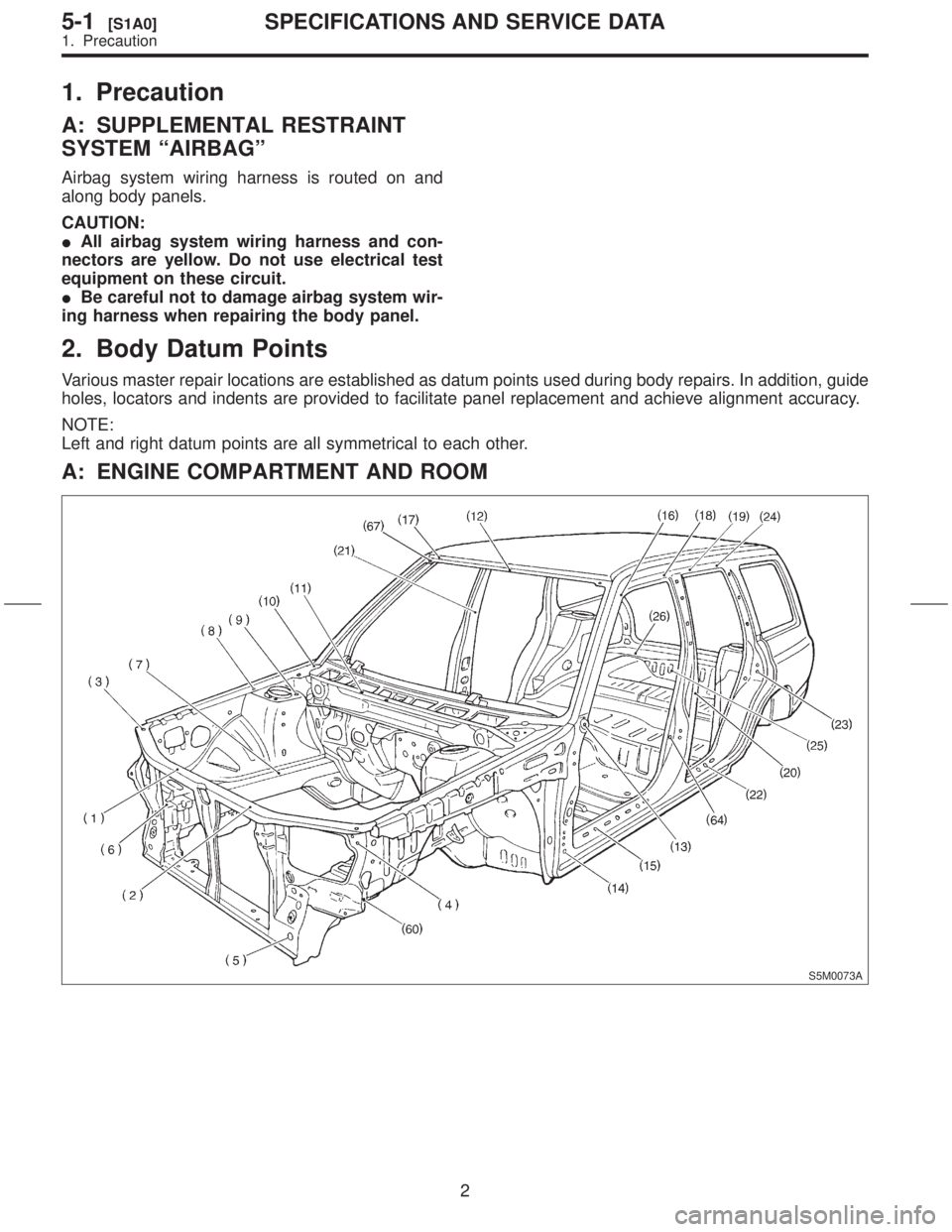
2. Body Datum Points
Various master repair locations are established as datum points used during body repairs. In addition, guide
holes, locators and indents are provided to facilitate panel replacement and achieve alignment accuracy.
NOTE:
Left and right datum points are all symmetrical to each other.
A: ENGINE COMPARTMENT AND ROOM
S5M0073A
2
5-1[S1A0]SPECIFICATIONS AND SERVICE DATA
1. Precaution
Page 158 of 345
1. Precaution
A: SUPPLEMENTAL RESTRAINT
SYSTEM ªAIRBAGº
Airbag system wiring harness is routed on and
along body panels.
CAUTION:
IAll airbag system wiring harness and con-
nectors are yellow. Do not use electrical test
equipment on these circuit.
IBe careful not to damage airbag system wir-
ing harness when repairing the body panel.
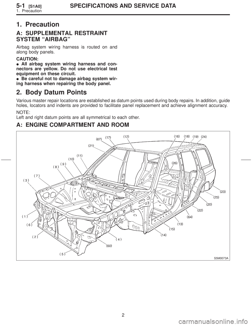
2. Body Datum Points
Various master repair locations are established as datum points used during body repairs. In addition, guide
holes, locators and indents are provided to facilitate panel replacement and achieve alignment accuracy.
NOTE:
Left and right datum points are all symmetrical to each other.
A: ENGINE COMPARTMENT AND ROOM
S5M0073A
2
5-1[S1A0]SPECIFICATIONS AND SERVICE DATA
1. Precaution
Page 159 of 345
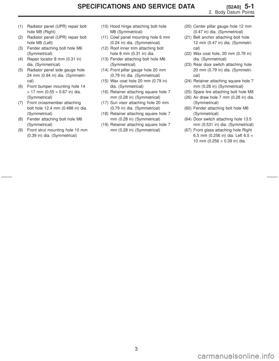
(1) Radiator panel (UPR) repair bolt
hole M8 (Right)
(2) Radiator panel (UPR) repair bolt
hole M8 (Left)
(3) Fender attaching bolt hole M6
(Symmetrical)
(4) Repair locator 8 mm (0.31 in)
dia. (Symmetrical)
(5) Radiator panel side gauge hole
24 mm (0.94 in) dia. (Symmetri-
cal)
(6) Front bumper mounting hole 14
´17 mm (0.55´0.67 in) dia.
(Symmetrical)
(7) Front crossmember attaching
bolt hole 12.4 mm (0.488 in) dia.
(Symmetrical)
(8) Fender attaching bolt hole M6
(Symmetrical)
(9) Front strut mounting hole 10 mm
(0.39 in) dia. (Symmetrical)(10) Hood hinge attaching bolt hole
M8 (Symmetrical)
(11) Cowl panel mounting hole 6 mm
(0.24 in) dia. (Symmetrical)
(12) Roof inner trim attaching bolt
hole 8 mm (0.31 in) dia.
(13) Fender attaching bolt hole M6
(Symmetrical)
(14) Front pillar gauge hole 20 mm
(0.79 in) dia. (Symmetrical)
(15) Wax coat hole 20 mm (0.79 in)
dia. (Symmetrical)
(16) Retainer attaching square hole 7
mm (0.28 in) (Symmetrical)
(17) Sun visor attaching hole 20 mm
(0.79 in) dia. (Symmetrical)
(18) Retainer attaching square hole 7
mm (0.28 in) (Symmetrical)
(19) Retainer attaching square hole 7
mm (0.28 in) (Symmetrical)(20) Center pillar gauge hole 12 mm
(0.47 in) dia. (Symmetrical)
(21) Belt anchor attaching bolt hole
12 mm (0.47 in) dia. (Symmetri-
cal)
(22) Wax coat hole, 20 mm (0.79 in)
dia. (Symmetrical)
(23) Rear door switch attaching hole
20 mm (0.79 in) dia. (Symmetri-
cal)
(24) Retainer attaching square hole 7
mm (0.28 in) (Symmetrical)
(25) Spare tire attaching bolt hole M8
(26) Air draw hole 7 mm (0.28 in) dia.
(Symmetrical)
(60) Fender attaching bolt hole M6
(Symmetrical)
(64) Door switch attaching hole 13.5
mm (0.531 in) dia. (Symmetrical)
(67) Front glass attaching hole Right
6.5 mm (0.256 in) dia. Left 6.5´
10 mm (0.256´0.39 in) dia.
3
[S2A0]5-1SPECIFICATIONS AND SERVICE DATA
2. Body Datum Points
Page 160 of 345
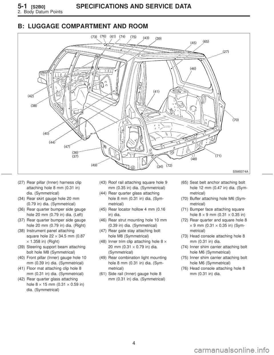
B: LUGGAGE COMPARTMENT AND ROOM
S5M0074A
(27) Rear pillar (Inner) harness clip
attaching hole 8 mm (0.31 in)
dia. (Symmetrical)
(34) Rear skirt gauge hole 20 mm
(0.79 in) dia. (Symmetrical)
(36) Rear quarter bumper side gauge
hole 20 mm (0.79 in) dia. (Left)
(37) Rear quarter bumper side gauge
hole 20 mm (0.79 in) dia. (Right)
(38) Instrument panel attaching
square hole 22´34.5 mm (0.87
´1.358 in) (Right)
(39) Steering support beam attaching
bolt hole M8 (Symmetrical)
(40) Front pillar (Inner) gauge hole 10
mm (0.39 in) dia. (Symmetrical)
(41) Floor mat attaching clip hole 8
mm (0.31 in) dia. (Symmetrical)
(42) Rear quarter glass attaching
hole 8´15 mm (0.31´0.59 in)
dia. (Symmetrical)(43) Roof rail attaching square hole 9
mm (0.35 in) dia. (Symmetrical)
(44) Rear quarter glass attaching
hole 8 mm (0.31 in) dia. (Sym-
metrical)
(45) Rear locator hollow 4 mm (0.16
in) dia.
(46) Rear strut mounting hole 10 mm
(0.39 in) dia. (Symmetrical)
(47) Rear gate stay attaching bolt
hole M8 (Symmetrical)
(48) Inner trim clip attaching hole 8´
20 mm (0.31´0.79 in) dia.
(Symmetrical)
(49) Rear combination light mounting
hole 8 mm (0.31 in) dia. (Sym-
metrical)
(61) Side rail (Inner) gauge hole 8
mm (0.31 in) dia. (Symmetrical)(65) Seat belt anchor attaching bolt
hole 12 mm (0.47 in) dia. (Sym-
metrical)
(70) Buffer attaching hole M6 (Sym-
metrical)
(71) Bumper face attaching square
hole 8´9 mm (0.31´0.35 in)
(72) Rear quarter and square hole 8
´9 mm (0.31´0.35 in) (Sym-
metrical)
(73) Head console attaching hole 8
mm (0.31 in) dia.
(74) Inner shim carrier attaching bolt
hole M6 (Symmetrical)
(75) Inner shim carrier attaching bolt
hole M6 (Symmetrical)
(76) Head console attaching hole 8
mm (0.31 in) dia.
4
5-1[S2B0]SPECIFICATIONS AND SERVICE DATA
2. Body Datum Points
Page 161 of 345
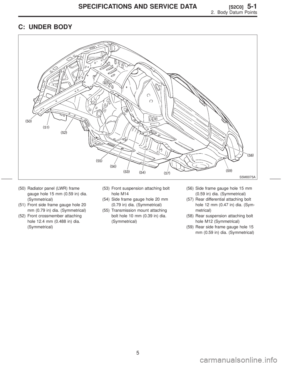
C: UNDER BODY
S5M0075A
(50) Radiator panel (LWR) frame
gauge hole 15 mm (0.59 in) dia.
(Symmetrical)
(51) Front side frame gauge hole 20
mm (0.79 in) dia. (Symmetrical)
(52) Front crossmember attaching
hole 12.4 mm (0.488 in) dia.
(Symmetrical)(53) Front suspension attaching bolt
hole M14
(54) Side frame gauge hole 20 mm
(0.79 in) dia. (Symmetrical)
(55) Transmission mount attaching
bolt hole 10 mm (0.39 in) dia.
(Symmetrical)(56) Side frame gauge hole 15 mm
(0.59 in) dia. (Symmetrical)
(57) Rear differential attaching bolt
hole 12 mm (0.47 in) dia. (Sym-
metrical)
(58) Rear suspension attaching bolt
hole M12 (Symmetrical)
(59) Rear side frame gauge hole 15
mm (0.59 in) dia. (Symmetrical)
5
[S2C0]5-1SPECIFICATIONS AND SERVICE DATA
2. Body Datum Points
Page 162 of 345
![SUBARU FORESTER 1999 Service Repair Manual D: DATUM POINT LOCATION
S5M0076AS5M0077A
S5M0078AS5M0079A
S5M0080AS5M0081A
6
5-1[S2D0]SPECIFICATIONS AND SERVICE DATA
2. Body Datum Points SUBARU FORESTER 1999 Service Repair Manual D: DATUM POINT LOCATION
S5M0076AS5M0077A
S5M0078AS5M0079A
S5M0080AS5M0081A
6
5-1[S2D0]SPECIFICATIONS AND SERVICE DATA
2. Body Datum Points](/img/17/57427/w960_57427-161.png)
D: DATUM POINT LOCATION
S5M0076AS5M0077A
S5M0078AS5M0079A
S5M0080AS5M0081A
6
5-1[S2D0]SPECIFICATIONS AND SERVICE DATA
2. Body Datum Points
Page 163 of 345
![SUBARU FORESTER 1999 Service Repair Manual S5M0082A
S5M0083A
S5M0084A
S5M0085A
S5M0086A
S5M0087A
S5M0088AS5M0089A
7
[S2D0]5-1SPECIFICATIONS AND SERVICE DATA
2. Body Datum Points SUBARU FORESTER 1999 Service Repair Manual S5M0082A
S5M0083A
S5M0084A
S5M0085A
S5M0086A
S5M0087A
S5M0088AS5M0089A
7
[S2D0]5-1SPECIFICATIONS AND SERVICE DATA
2. Body Datum Points](/img/17/57427/w960_57427-162.png)
S5M0082A
S5M0083A
S5M0084A
S5M0085A
S5M0086A
S5M0087A
S5M0088AS5M0089A
7
[S2D0]5-1SPECIFICATIONS AND SERVICE DATA
2. Body Datum Points
Page 164 of 345
![SUBARU FORESTER 1999 Service Repair Manual S5M0090A
S5M0091A
S5M0092AS5M0093A
S5M0094AS5M0095A
S5M0096A
S5M0097A
8
5-1[S2D0]SPECIFICATIONS AND SERVICE DATA
2. Body Datum Points SUBARU FORESTER 1999 Service Repair Manual S5M0090A
S5M0091A
S5M0092AS5M0093A
S5M0094AS5M0095A
S5M0096A
S5M0097A
8
5-1[S2D0]SPECIFICATIONS AND SERVICE DATA
2. Body Datum Points](/img/17/57427/w960_57427-163.png)
S5M0090A
S5M0091A
S5M0092AS5M0093A
S5M0094AS5M0095A
S5M0096A
S5M0097A
8
5-1[S2D0]SPECIFICATIONS AND SERVICE DATA
2. Body Datum Points
Page 165 of 345
![SUBARU FORESTER 1999 Service Repair Manual S5M0098AS5M0099A
S5M0100AS5M0101A
S5M0102AS5M0103A
S5M0104AS5M0105A
9
[S2D0]5-1SPECIFICATIONS AND SERVICE DATA
2. Body Datum Points SUBARU FORESTER 1999 Service Repair Manual S5M0098AS5M0099A
S5M0100AS5M0101A
S5M0102AS5M0103A
S5M0104AS5M0105A
9
[S2D0]5-1SPECIFICATIONS AND SERVICE DATA
2. Body Datum Points](/img/17/57427/w960_57427-164.png)
S5M0098AS5M0099A
S5M0100AS5M0101A
S5M0102AS5M0103A
S5M0104AS5M0105A
9
[S2D0]5-1SPECIFICATIONS AND SERVICE DATA
2. Body Datum Points