transmission SUBARU FORESTER 1999 Service Repair Manual
[x] Cancel search | Manufacturer: SUBARU, Model Year: 1999, Model line: FORESTER, Model: SUBARU FORESTER 1999Pages: 345, PDF Size: 5.6 MB
Page 65 of 345
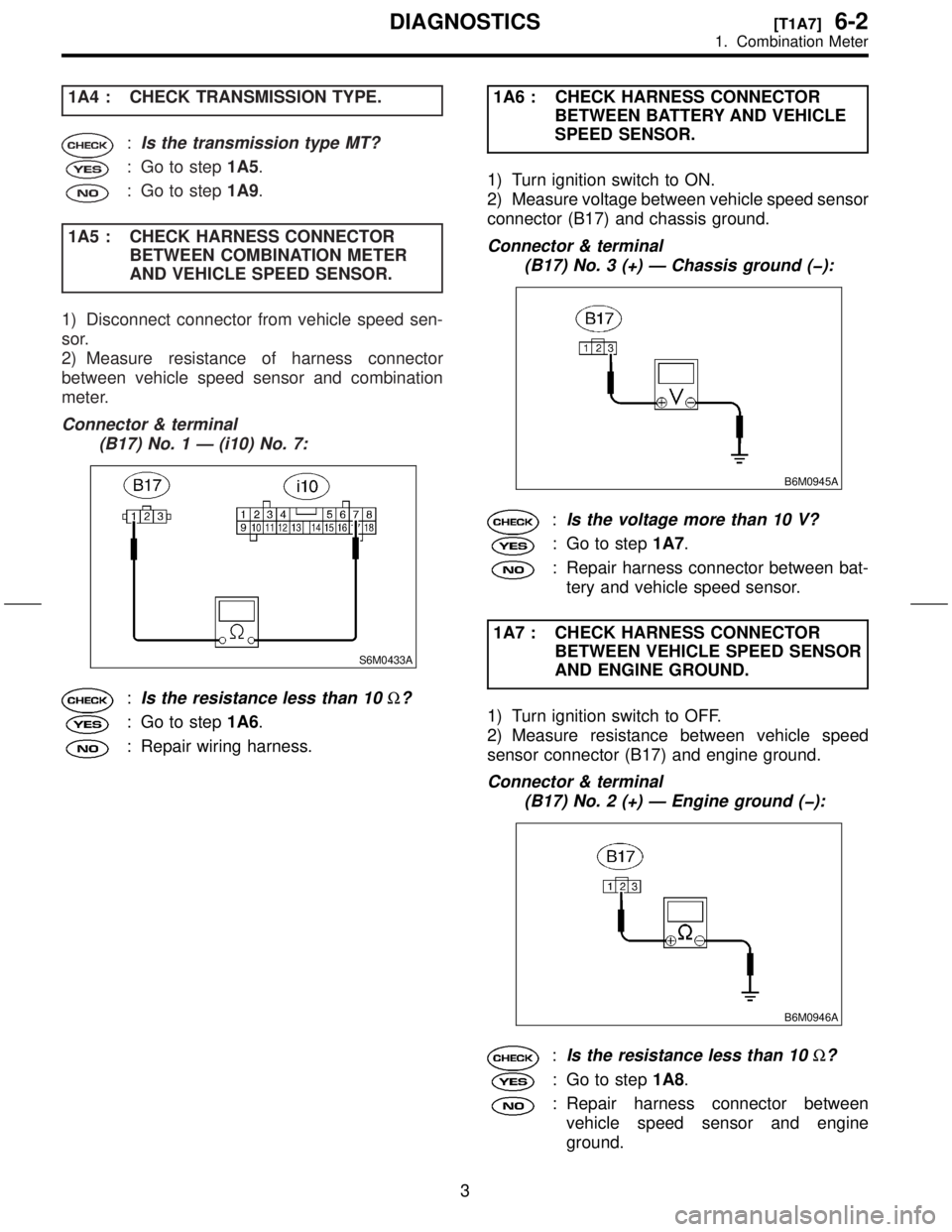
1A4 : CHECK TRANSMISSION TYPE.
:Is the transmission type MT?
: Go to step1A5.
: Go to step1A9.
1A5 : CHECK HARNESS CONNECTOR
BETWEEN COMBINATION METER
AND VEHICLE SPEED SENSOR.
1) Disconnect connector from vehicle speed sen-
sor.
2) Measure resistance of harness connector
between vehicle speed sensor and combination
meter.
Connector & terminal
(B17) No. 1 Ð (i10) No. 7:
S6M0433A
:Is the resistance less than 10W?
: Go to step1A6.
: Repair wiring harness.1A6 : CHECK HARNESS CONNECTOR
BETWEEN BATTERY AND VEHICLE
SPEED SENSOR.
1) Turn ignition switch to ON.
2) Measure voltage between vehicle speed sensor
connector (B17) and chassis ground.
Connector & terminal
(B17) No. 3 (+) Ð Chassis ground (þ):
B6M0945A
:Is the voltage more than 10 V?
: Go to step1A7.
: Repair harness connector between bat-
tery and vehicle speed sensor.
1A7 : CHECK HARNESS CONNECTOR
BETWEEN VEHICLE SPEED SENSOR
AND ENGINE GROUND.
1) Turn ignition switch to OFF.
2) Measure resistance between vehicle speed
sensor connector (B17) and engine ground.
Connector & terminal
(B17) No. 2 (+) Ð Engine ground (þ):
B6M0946A
:Is the resistance less than 10W?
: Go to step1A8.
: Repair harness connector between
vehicle speed sensor and engine
ground.
3
[T1A7]6-2DIAGNOSTICS
1. Combination Meter
Page 66 of 345

1A8 : CHECK VEHICLE SPEED SENSOR.
1) Connect connector to vehicle speed sensor.
2) Set the vehicle on a free roller, or lift-up the
vehicle and support with safety stands.
WARNING:
Be careful not to get caught in the rotating
wheels.
3) Set oscilloscope to vehicle speed sensor con-
nector terminals.
Positive probe; (B17) No. 1
Earth lead; (B17) No. 2
H6M0789A
4) Drive the vehicle at speed greater than 20 km/h
(12 MPH).
5) Measure signal voltage indicated on oscillo-
scope.
H6M0790A
:Is the voltage more than 5 V?
: Repair or replace speedometer.
: Replace vehicle speed sensor.
BETWEEN COMBINATION METER
AND AUTOMATIC TRANSMISSION
CONTROL MODULE.
1) Disconnect connector from automatic transmis-
sion control module.
2) Measure resistance between combination
meter connector (i10) and automatic transmission
control module connector (B56).
CAUTION:
To measure the voltage and/or resistance, use
a tapered pin with a diameter of less than 0.64
mm (0.025 in). Do not insert the pin more than
5 mm (0.20 in).
Connector & terminal
(i10) No. 7 Ð (B56) No. 17:
S6M0434A
:Is the resistance less than 10W?
: Go to step1A10.
: Repair harness connector between
combination meter and automatic trans-
mission control module.
4
6-2[T1A8]DIAGNOSTICS
1. Combination Meter
Page 67 of 345
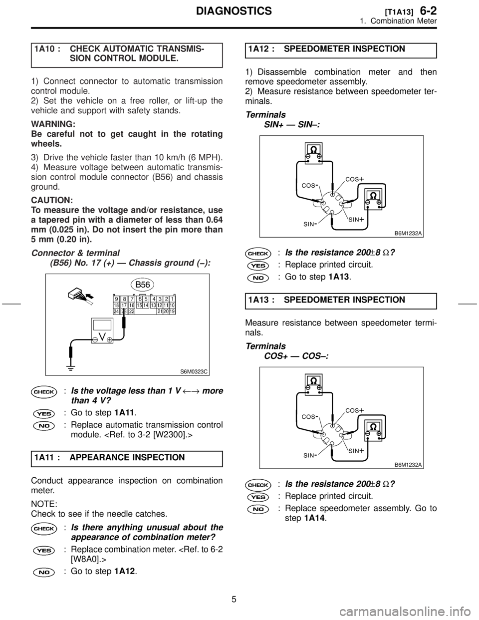
1A10 : CHECK AUTOMATIC TRANSMIS-
SION CONTROL MODULE.
1) Connect connector to automatic transmission
control module.
2) Set the vehicle on a free roller, or lift-up the
vehicle and support with safety stands.
WARNING:
Be careful not to get caught in the rotating
wheels.
3) Drive the vehicle faster than 10 km/h (6 MPH).
4) Measure voltage between automatic transmis-
sion control module connector (B56) and chassis
ground.
CAUTION:
To measure the voltage and/or resistance, use
a tapered pin with a diameter of less than 0.64
mm (0.025 in). Do not insert the pin more than
5 mm (0.20 in).
Connector & terminal
(B56) No. 17 (+) Ð Chassis ground (þ):
S6M0323C
:Is the voltage less than 1 V¨more
than 4 V?
: Go to step1A11.
: Replace automatic transmission control
module.
1A11 : APPEARANCE INSPECTION
Conduct appearance inspection on combination
meter.
NOTE:
Check to see if the needle catches.
:Is there anything unusual about the
appearance of combination meter?
: Replace combination meter.
: Go to step1A12.1A12 : SPEEDOMETER INSPECTION
1) Disassemble combination meter and then
remove speedometer assembly.
2) Measure resistance between speedometer ter-
minals.
Terminals
SIN+ Ð SIN±:
B6M1232A
:Is the resistance 200±8W?
: Replace printed circuit.
: Go to step1A13.
1A13 : SPEEDOMETER INSPECTION
Measure resistance between speedometer termi-
nals.
Terminals
COS+ Ð COS±:
B6M1232A
:Is the resistance 200±8W?
: Replace printed circuit.
: Replace speedometer assembly. Go to
step1A14.
5
[T1A13]6-2DIAGNOSTICS
1. Combination Meter
Page 82 of 345
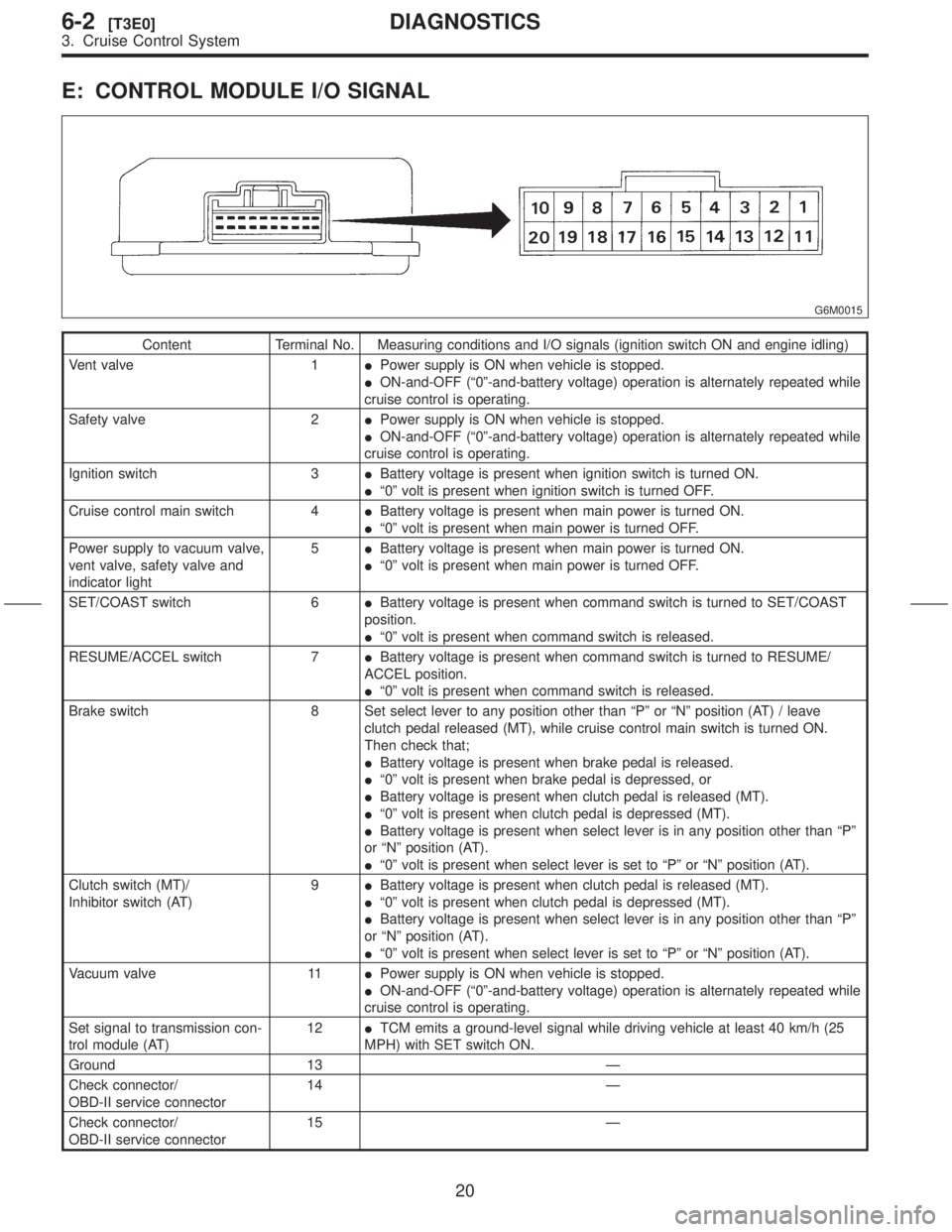
E: CONTROL MODULE I/O SIGNAL
G6M0015
Content Terminal No. Measuring conditions and I/O signals (ignition switch ON and engine idling)
Vent valve 1IPower supply is ON when vehicle is stopped.
ION-and-OFF (ª0º-and-battery voltage) operation is alternately repeated while
cruise control is operating.
Safety valve 2IPower supply is ON when vehicle is stopped.
ION-and-OFF (ª0º-and-battery voltage) operation is alternately repeated while
cruise control is operating.
Ignition switch 3IBattery voltage is present when ignition switch is turned ON.
Iª0º volt is present when ignition switch is turned OFF.
Cruise control main switch 4IBattery voltage is present when main power is turned ON.
Iª0º volt is present when main power is turned OFF.
Power supply to vacuum valve,
vent valve, safety valve and
indicator light5IBattery voltage is present when main power is turned ON.
Iª0º volt is present when main power is turned OFF.
SET/COAST switch 6IBattery voltage is present when command switch is turned to SET/COAST
position.
Iª0º volt is present when command switch is released.
RESUME/ACCEL switch 7IBattery voltage is present when command switch is turned to RESUME/
ACCEL position.
Iª0º volt is present when command switch is released.
Brake switch 8 Set select lever to any position other than ªPº or ªNº position (AT) / leave
clutch pedal released (MT), while cruise control main switch is turned ON.
Then check that;
IBattery voltage is present when brake pedal is released.
Iª0º volt is present when brake pedal is depressed, or
IBattery voltage is present when clutch pedal is released (MT).
Iª0º volt is present when clutch pedal is depressed (MT).
IBattery voltage is present when select lever is in any position other than ªPº
or ªNº position (AT).
Iª0º volt is present when select lever is set to ªPº or ªNº position (AT).
Clutch switch (MT)/
Inhibitor switch (AT)9IBattery voltage is present when clutch pedal is released (MT).
Iª0º volt is present when clutch pedal is depressed (MT).
IBattery voltage is present when select lever is in any position other than ªPº
or ªNº position (AT).
Iª0º volt is present when select lever is set to ªPº or ªNº position (AT).
Vacuum valve 11IPower supply is ON when vehicle is stopped.
ION-and-OFF (ª0º-and-battery voltage) operation is alternately repeated while
cruise control is operating.
Set signal to transmission con-
trol module (AT)12ITCM emits a ground-level signal while driving vehicle at least 40 km/h (25
MPH) with SET switch ON.
Ground 13 Ð
Check connector/
OBD-II service connector14 Ð
Check connector/
OBD-II service connector15 Ð
20
6-2[T3E0]DIAGNOSTICS
3. Cruise Control System
Page 83 of 345

Content Terminal No. Measuring conditions and I/O signals (ignition switch ON and engine idling)
Vehicle speed sensor (MT)
Automatic transmission control
module (AT)18 Lift-up the vehicle until all four wheels are raised off ground, and then rotate
any wheel manually. Approx. 5 and 0 volt pulse signals are alternately input to
cruise control module.
Stop light switch 19 Turn ignition switch to OFF. Then check that;
IBattery voltage is present when brake pedal is depressed.
Iª0º volt is present when brake pedal is released.
Ground 20 Ð
NOTE:
Voltage at terminals 1, 2, 11 and 12 cannot be checked unless vehicle is driving by cruise control operation.
21
[T3E0]6-2DIAGNOSTICS
3. Cruise Control System
Page 91 of 345
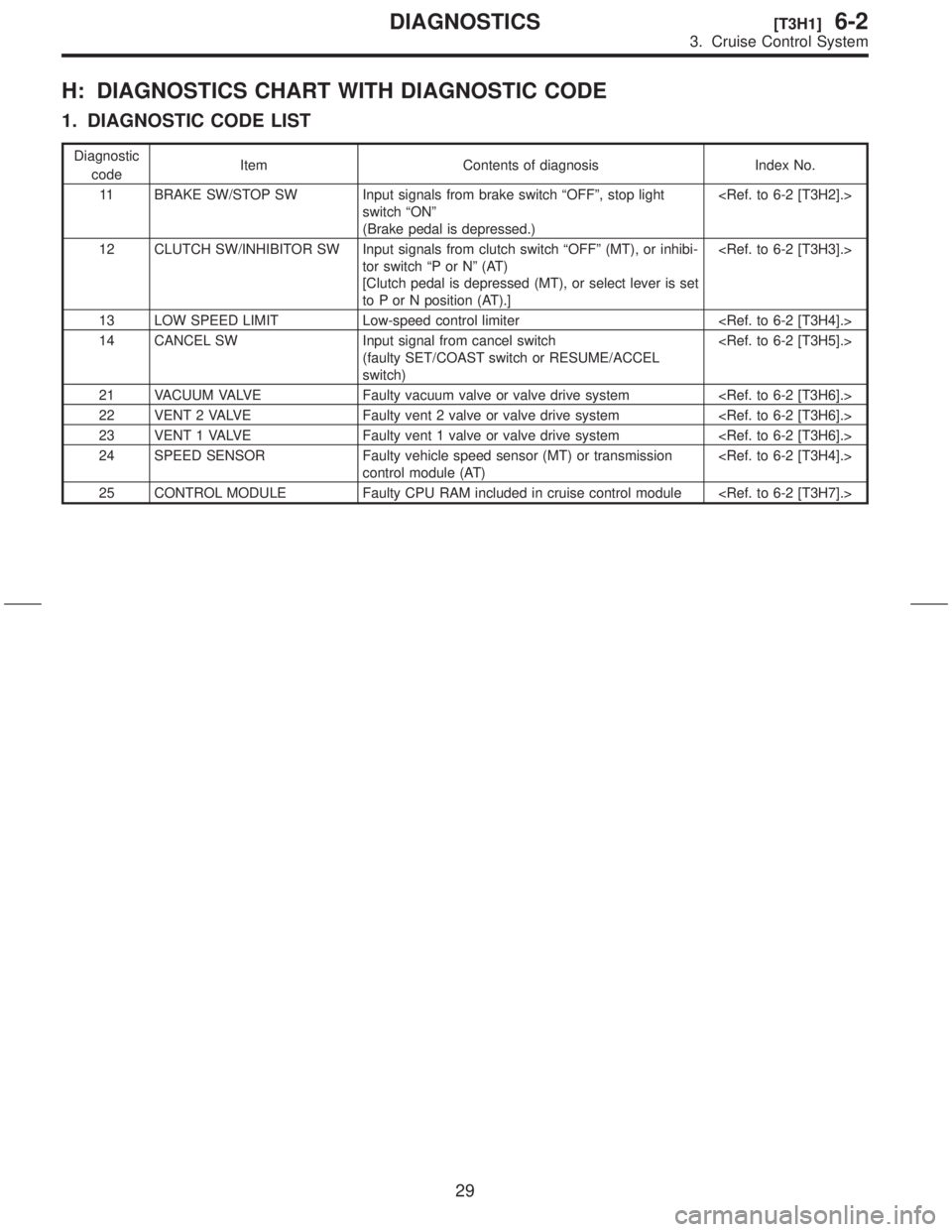
H: DIAGNOSTICS CHART WITH DIAGNOSTIC CODE
1. DIAGNOSTIC CODE LIST
Diagnostic
codeItem Contents of diagnosis Index No.
11 BRAKE SW/STOP SW Input signals from brake switch ªOFFº, stop light
switch ªONº
(Brake pedal is depressed.)
12 CLUTCH SW/INHIBITOR SW Input signals from clutch switch ªOFFº (MT), or inhibi-
tor switch ªP or Nº (AT)
[Clutch pedal is depressed (MT), or select lever is set
to P or N position (AT).]
13 LOW SPEED LIMIT Low-speed control limiter
14 CANCEL SW Input signal from cancel switch
(faulty SET/COAST switch or RESUME/ACCEL
switch)
21 VACUUM VALVE Faulty vacuum valve or valve drive system
22 VENT 2 VALVE Faulty vent 2 valve or valve drive system
23 VENT 1 VALVE Faulty vent 1 valve or valve drive system
24 SPEED SENSOR Faulty vehicle speed sensor (MT) or transmission
control module (AT)
25 CONTROL MODULE Faulty CPU RAM included in cruise control module
29
[T3H1]6-2DIAGNOSTICS
3. Cruise Control System
Page 100 of 345

4. DIAGNOSTIC CODE 13 AND 24 (SPEED SENSOR SYSTEM)
DIAGNOSIS:
IDisconnection or short circuit of vehicle speed sensor (MT model) or transmission control module (AT
model).
TROUBLE SYMPTOM:
ICruise control cannot be set. (Cancelled immediately.)
WIRING DIAGRAM:
S6M0421
38
6-2[T3H4]DIAGNOSTICS
3. Cruise Control System
Page 101 of 345
3H41 : CHECK TRANSMISSION TYPE.
:Is the transmission type MT?
: Go to step3H42.
: Go to step3H46.
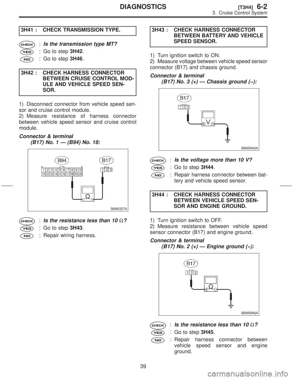
3H42 : CHECK HARNESS CONNECTOR
BETWEEN CRUISE CONTROL MOD-
ULE AND VEHICLE SPEED SEN-
SOR.
1) Disconnect connector from vehicle speed sen-
sor and cruise control module.
2) Measure resistance of harness connector
between vehicle speed sensor and cruise control
module.
Connector & terminal
(B17) No. 1 Ð (B94) No. 18:
S6M0327A
:Is the resistance less than 10W?
: Go to step3H43.
: Repair wiring harness.3H43 : CHECK HARNESS CONNECTOR
BETWEEN BATTERY AND VEHICLE
SPEED SENSOR.
1) Turn ignition switch to ON.
2) Measure voltage between vehicle speed sensor
connector (B17) and chassis ground.
Connector & terminal
(B17) No. 3 (+) Ð Chassis ground (þ):
B6M0945A
:Is the voltage more than 10 V?
: Go to step3H44.
: Repair harness connector between bat-
tery and vehicle speed sensor.
3H44 : CHECK HARNESS CONNECTOR
BETWEEN VEHICLE SPEED SEN-
SOR AND ENGINE GROUND.
1) Turn ignition switch to OFF.
2) Measure resistance between vehicle speed
sensor connector (B17) and engine ground.
Connector & terminal
(B17) No. 2 (+) Ð Engine ground (þ):
B6M0946A
:Is the resistance less than 10W?
: Go to step3H45.
: Repair harness connector between
vehicle speed sensor and engine
ground.
39
[T3H4]6-2DIAGNOSTICS
3. Cruise Control System
Page 102 of 345

3H45 : CHECK VEHICLE SPEED SENSOR.
1) Connect connector to vehicle speed sensor.
2) Set the vehicle on free roller, or lift-up the
vehicle and support with safety stands.
WARNING:
Be careful not to be caught up by the running
wheels.
3) Set oscilloscope to vehicle speed sensor con-
nector terminals.
Positive probe; (B17) No. 1
Earth lead; (B17) No. 2
H6M0789A
4) Drive the vehicle at speed greater than 20 km/h
(12 MPH).
5) Measure signal voltage indicated on oscillo-
scope.
H6M0790A
:Is the voltage more than 5 V?
: Replace cruise control module.
: Replace vehicle speed sensor.
BETWEEN CRUISE CONTROL MOD-
ULE AND AUTOMATIC TRANSMIS-
SION CONTROL MODULE.
1) Disconnect connector from automatic transmis-
sion control module and cruise control module.
2) Measure resistance between cruise control
module connector and automatic transmission
control module connector.
CAUTION:
To measure the voltage and/or resistance, use
a tapered pin with a diameter of less than 0.64
mm (0.025 in). Do not insert the pin more than
5 mm (0.20 in).
Connector & terminal
(B94) No. 18 Ð (B56) No. 17:
S6M0341A
:Is the resistance less than 10W?
: Go to step3H47.
: Repair harness connector between
cruise control module and automatic
transmission control module.
40
6-2[T3H4]DIAGNOSTICS
3. Cruise Control System
Page 103 of 345
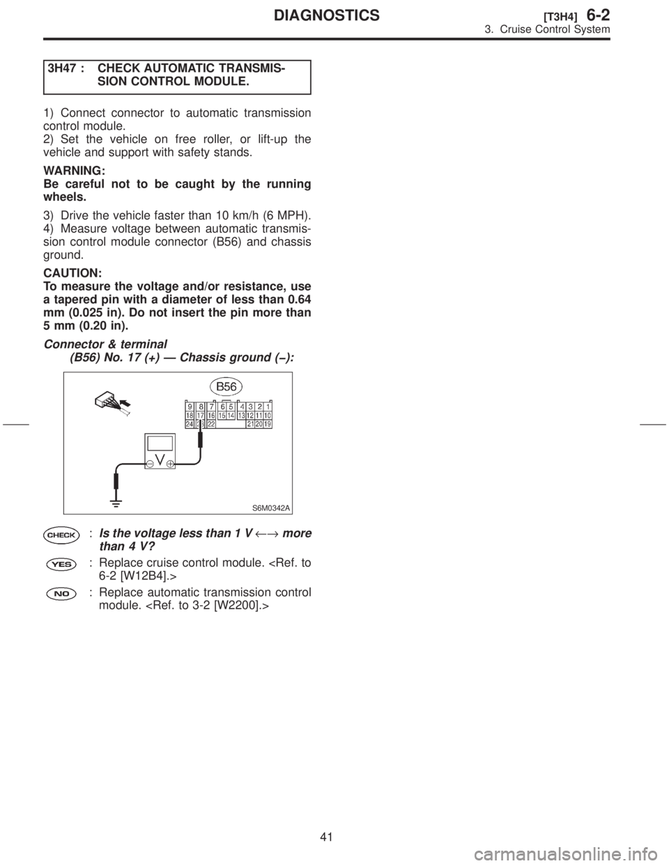
3H47 : CHECK AUTOMATIC TRANSMIS-
SION CONTROL MODULE.
1) Connect connector to automatic transmission
control module.
2) Set the vehicle on free roller, or lift-up the
vehicle and support with safety stands.
WARNING:
Be careful not to be caught by the running
wheels.
3) Drive the vehicle faster than 10 km/h (6 MPH).
4) Measure voltage between automatic transmis-
sion control module connector (B56) and chassis
ground.
CAUTION:
To measure the voltage and/or resistance, use
a tapered pin with a diameter of less than 0.64
mm (0.025 in). Do not insert the pin more than
5 mm (0.20 in).
Connector & terminal
(B56) No. 17 (+) Ð Chassis ground (þ):
S6M0342A
:Is the voltage less than 1 V¨more
than 4 V?
: Replace cruise control module.
: Replace automatic transmission control
module.
41
[T3H4]6-2DIAGNOSTICS
3. Cruise Control System