wheel SUBARU FORESTER 1999 Service Repair Manual
[x] Cancel search | Manufacturer: SUBARU, Model Year: 1999, Model line: FORESTER, Model: SUBARU FORESTER 1999Pages: 345, PDF Size: 5.6 MB
Page 60 of 345
3) Conduct appearance inspection on parts
selected.
NOTE:
Also check connector terminals, wiring harness,
case, etc. for damage.
:Is there anything unusual about the
appearance of airbag component
parts?
: Replace faulty airbag component parts.
: Go to step5X2.
5X2 : AIRBAG COMPONENT PARTS
VIBRATION INSPECTION
1) Gently shake check parts (to determine faults.).
2) To check airbag module or roll connector, turn
and tilt steering wheel.
CAUTION:
Do not shake or vibrate airbag control module.
:Does the component malfunction
again when shaking?
: Replace faulty airbag component parts.
: Go to step5X3.
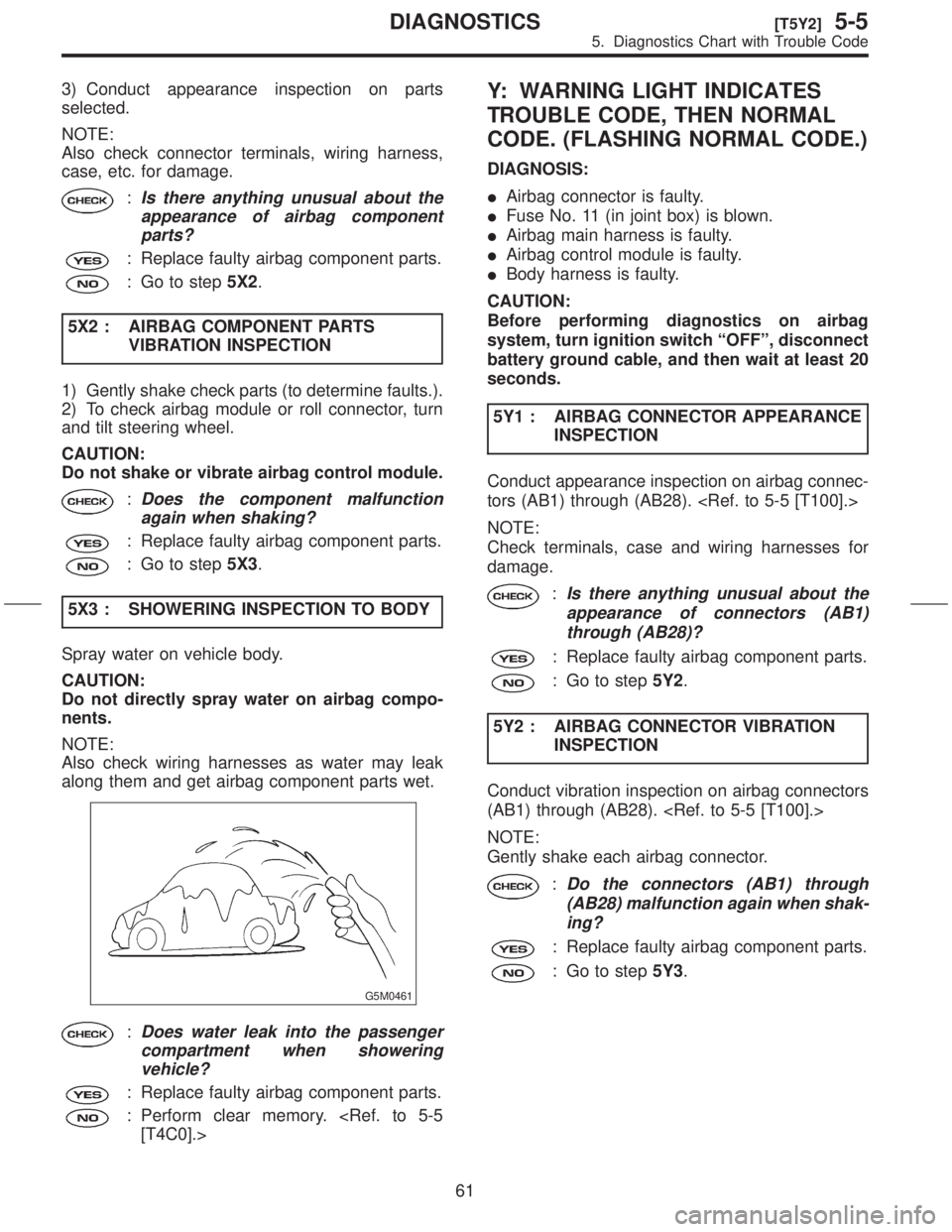
5X3 : SHOWERING INSPECTION TO BODY
Spray water on vehicle body.
CAUTION:
Do not directly spray water on airbag compo-
nents.
NOTE:
Also check wiring harnesses as water may leak
along them and get airbag component parts wet.
G5M0461
:Does water leak into the passenger
compartment when showering
vehicle?
: Replace faulty airbag component parts.
: Perform clear memory.
Y: WARNING LIGHT INDICATES
TROUBLE CODE, THEN NORMAL
CODE. (FLASHING NORMAL CODE.)
DIAGNOSIS:
IAirbag connector is faulty.
IFuse No. 11 (in joint box) is blown.
IAirbag main harness is faulty.
IAirbag control module is faulty.
IBody harness is faulty.
CAUTION:
Before performing diagnostics on airbag
system, turn ignition switch ªOFFº, disconnect
battery ground cable, and then wait at least 20
seconds.
5Y1 : AIRBAG CONNECTOR APPEARANCE
INSPECTION
Conduct appearance inspection on airbag connec-
tors (AB1) through (AB28).
NOTE:
Check terminals, case and wiring harnesses for
damage.
:Is there anything unusual about the
appearance of connectors (AB1)
through (AB28)?
: Replace faulty airbag component parts.
: Go to step5Y2.
5Y2 : AIRBAG CONNECTOR VIBRATION
INSPECTION
Conduct vibration inspection on airbag connectors
(AB1) through (AB28).
NOTE:
Gently shake each airbag connector.
:Do the connectors (AB1) through
(AB28) malfunction again when shak-
ing?
: Replace faulty airbag component parts.
: Go to step5Y3.
61
[T5Y2]5-5DIAGNOSTICS
5. Diagnostics Chart with Trouble Code
Page 66 of 345
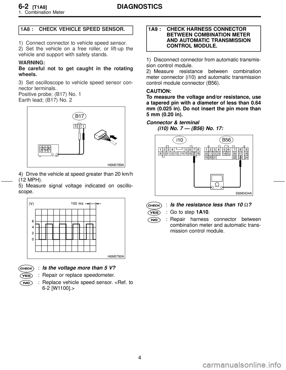
1A8 : CHECK VEHICLE SPEED SENSOR.
1) Connect connector to vehicle speed sensor.
2) Set the vehicle on a free roller, or lift-up the
vehicle and support with safety stands.
WARNING:
Be careful not to get caught in the rotating
wheels.
3) Set oscilloscope to vehicle speed sensor con-
nector terminals.
Positive probe; (B17) No. 1
Earth lead; (B17) No. 2
H6M0789A
4) Drive the vehicle at speed greater than 20 km/h
(12 MPH).
5) Measure signal voltage indicated on oscillo-
scope.
H6M0790A
:Is the voltage more than 5 V?
: Repair or replace speedometer.
: Replace vehicle speed sensor.
BETWEEN COMBINATION METER
AND AUTOMATIC TRANSMISSION
CONTROL MODULE.
1) Disconnect connector from automatic transmis-
sion control module.
2) Measure resistance between combination
meter connector (i10) and automatic transmission
control module connector (B56).
CAUTION:
To measure the voltage and/or resistance, use
a tapered pin with a diameter of less than 0.64
mm (0.025 in). Do not insert the pin more than
5 mm (0.20 in).
Connector & terminal
(i10) No. 7 Ð (B56) No. 17:
S6M0434A
:Is the resistance less than 10W?
: Go to step1A10.
: Repair harness connector between
combination meter and automatic trans-
mission control module.
4
6-2[T1A8]DIAGNOSTICS
1. Combination Meter
Page 67 of 345
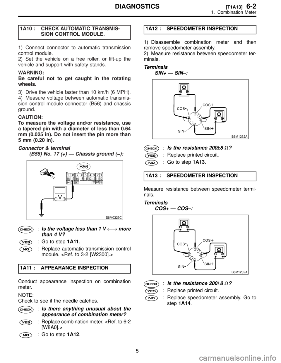
1A10 : CHECK AUTOMATIC TRANSMIS-
SION CONTROL MODULE.
1) Connect connector to automatic transmission
control module.
2) Set the vehicle on a free roller, or lift-up the
vehicle and support with safety stands.
WARNING:
Be careful not to get caught in the rotating
wheels.
3) Drive the vehicle faster than 10 km/h (6 MPH).
4) Measure voltage between automatic transmis-
sion control module connector (B56) and chassis
ground.
CAUTION:
To measure the voltage and/or resistance, use
a tapered pin with a diameter of less than 0.64
mm (0.025 in). Do not insert the pin more than
5 mm (0.20 in).
Connector & terminal
(B56) No. 17 (+) Ð Chassis ground (þ):
S6M0323C
:Is the voltage less than 1 V¨more
than 4 V?
: Go to step1A11.
: Replace automatic transmission control
module.
1A11 : APPEARANCE INSPECTION
Conduct appearance inspection on combination
meter.
NOTE:
Check to see if the needle catches.
:Is there anything unusual about the
appearance of combination meter?
: Replace combination meter.
: Go to step1A12.1A12 : SPEEDOMETER INSPECTION
1) Disassemble combination meter and then
remove speedometer assembly.
2) Measure resistance between speedometer ter-
minals.
Terminals
SIN+ Ð SIN±:
B6M1232A
:Is the resistance 200±8W?
: Replace printed circuit.
: Go to step1A13.
1A13 : SPEEDOMETER INSPECTION
Measure resistance between speedometer termi-
nals.
Terminals
COS+ Ð COS±:
B6M1232A
:Is the resistance 200±8W?
: Replace printed circuit.
: Replace speedometer assembly. Go to
step1A14.
5
[T1A13]6-2DIAGNOSTICS
1. Combination Meter
Page 83 of 345
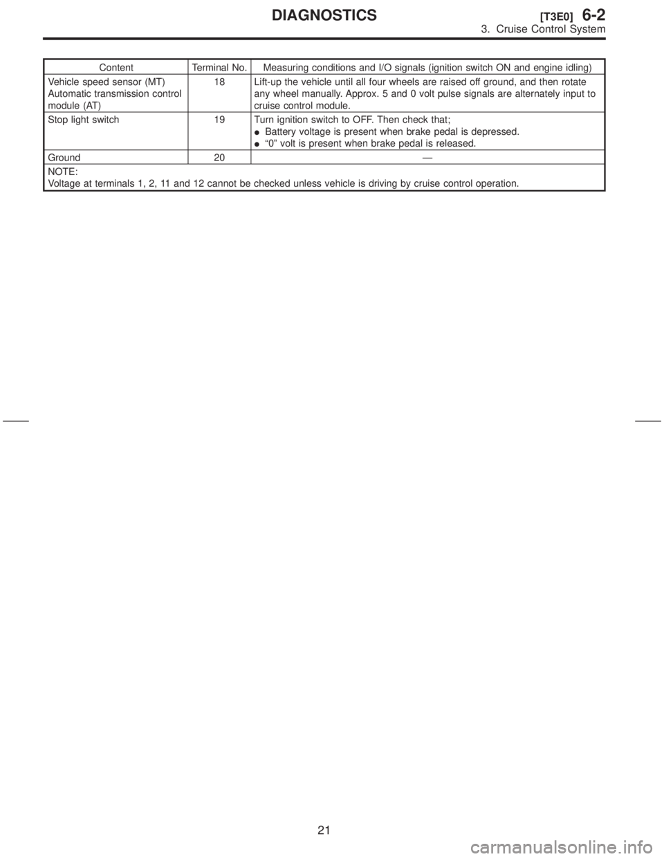
Content Terminal No. Measuring conditions and I/O signals (ignition switch ON and engine idling)
Vehicle speed sensor (MT)
Automatic transmission control
module (AT)18 Lift-up the vehicle until all four wheels are raised off ground, and then rotate
any wheel manually. Approx. 5 and 0 volt pulse signals are alternately input to
cruise control module.
Stop light switch 19 Turn ignition switch to OFF. Then check that;
IBattery voltage is present when brake pedal is depressed.
Iª0º volt is present when brake pedal is released.
Ground 20 Ð
NOTE:
Voltage at terminals 1, 2, 11 and 12 cannot be checked unless vehicle is driving by cruise control operation.
21
[T3E0]6-2DIAGNOSTICS
3. Cruise Control System
Page 102 of 345
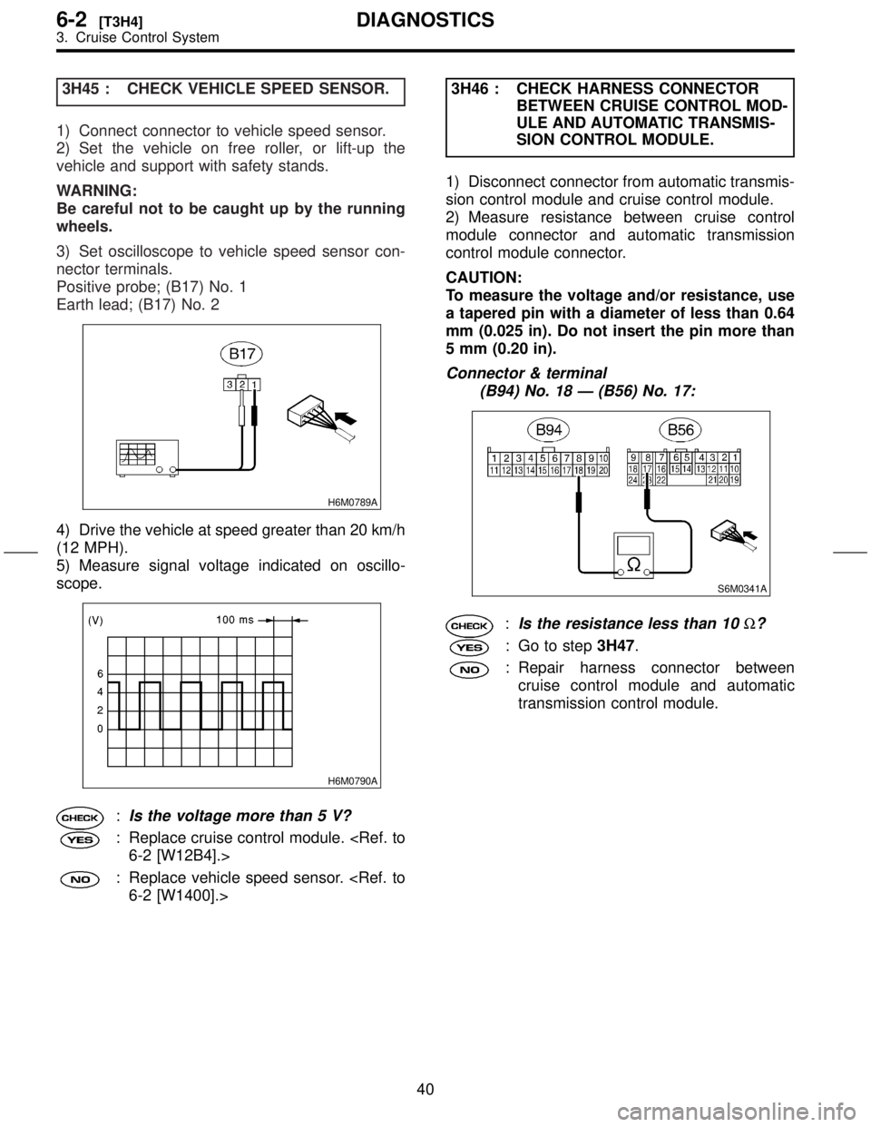
3H45 : CHECK VEHICLE SPEED SENSOR.
1) Connect connector to vehicle speed sensor.
2) Set the vehicle on free roller, or lift-up the
vehicle and support with safety stands.
WARNING:
Be careful not to be caught up by the running
wheels.
3) Set oscilloscope to vehicle speed sensor con-
nector terminals.
Positive probe; (B17) No. 1
Earth lead; (B17) No. 2
H6M0789A
4) Drive the vehicle at speed greater than 20 km/h
(12 MPH).
5) Measure signal voltage indicated on oscillo-
scope.
H6M0790A
:Is the voltage more than 5 V?
: Replace cruise control module.
: Replace vehicle speed sensor.
BETWEEN CRUISE CONTROL MOD-
ULE AND AUTOMATIC TRANSMIS-
SION CONTROL MODULE.
1) Disconnect connector from automatic transmis-
sion control module and cruise control module.
2) Measure resistance between cruise control
module connector and automatic transmission
control module connector.
CAUTION:
To measure the voltage and/or resistance, use
a tapered pin with a diameter of less than 0.64
mm (0.025 in). Do not insert the pin more than
5 mm (0.20 in).
Connector & terminal
(B94) No. 18 Ð (B56) No. 17:
S6M0341A
:Is the resistance less than 10W?
: Go to step3H47.
: Repair harness connector between
cruise control module and automatic
transmission control module.
40
6-2[T3H4]DIAGNOSTICS
3. Cruise Control System
Page 103 of 345
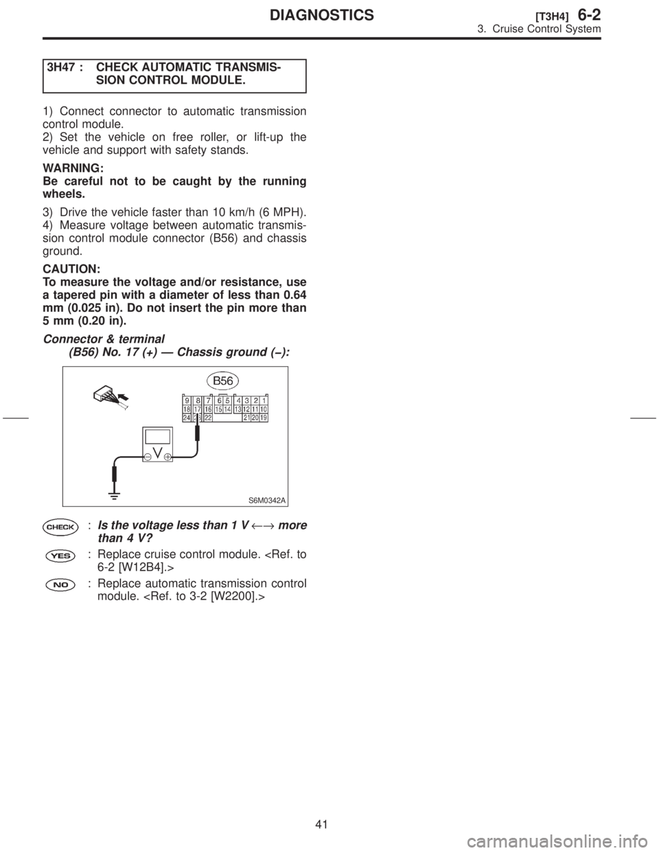
3H47 : CHECK AUTOMATIC TRANSMIS-
SION CONTROL MODULE.
1) Connect connector to automatic transmission
control module.
2) Set the vehicle on free roller, or lift-up the
vehicle and support with safety stands.
WARNING:
Be careful not to be caught by the running
wheels.
3) Drive the vehicle faster than 10 km/h (6 MPH).
4) Measure voltage between automatic transmis-
sion control module connector (B56) and chassis
ground.
CAUTION:
To measure the voltage and/or resistance, use
a tapered pin with a diameter of less than 0.64
mm (0.025 in). Do not insert the pin more than
5 mm (0.20 in).
Connector & terminal
(B56) No. 17 (+) Ð Chassis ground (þ):
S6M0342A
:Is the voltage less than 1 V¨more
than 4 V?
: Replace cruise control module.
: Replace automatic transmission control
module.
41
[T3H4]6-2DIAGNOSTICS
3. Cruise Control System
Page 194 of 345
Process
No.Process name Job contents
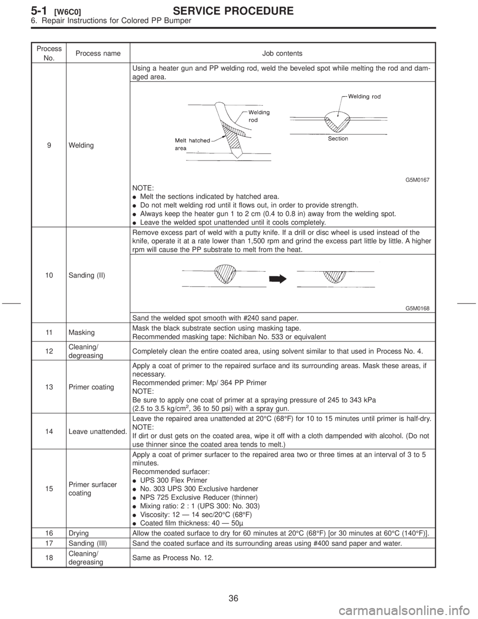
9 WeldingUsing a heater gun and PP welding rod, weld the beveled spot while melting the rod and dam-
aged area.
G5M0167
NOTE:
IMelt the sections indicated by hatched area.
IDo not melt welding rod until it flows out, in order to provide strength.
IAlways keep the heater gun 1 to 2 cm (0.4 to 0.8 in) away from the welding spot.
ILeave the welded spot unattended until it cools completely.
10 Sanding (II)Remove excess part of weld with a putty knife. If a drill or disc wheel is used instead of the
knife, operate it at a rate lower than 1,500 rpm and grind the excess part little by little. A higher
rpm will cause the PP substrate to melt from the heat.
G5M0168
Sand the welded spot smooth with #240 sand paper.
11 MaskingMask the black substrate section using masking tape.
Recommended masking tape: Nichiban No. 533 or equivalent
12Cleaning/
degreasingCompletely clean the entire coated area, using solvent similar to that used in Process No. 4.
13 Primer coatingApply a coat of primer to the repaired surface and its surrounding areas. Mask these areas, if
necessary.
Recommended primer: Mp/ 364 PP Primer
NOTE:
Be sure to apply one coat of primer at a spraying pressure of 245 to 343 kPa
(2.5 to 3.5 kg/cm
2, 36 to 50 psi) with a spray gun.
14 Leave unattended.Leave the repaired area unattended at 20ÉC (68ÉF) for 10 to 15 minutes until primer is half-dry.
NOTE:
If dirt or dust gets on the coated area, wipe it off with a cloth dampended with alcohol. (Do not
use thinner since the coated area tends to melt.)
15Primer surfacer
coatingApply a coat of primer surfacer to the repaired area two or three times at an interval of 3 to 5
minutes.
Recommended surfacer:
IUPS 300 Flex Primer
INo. 303 UPS 300 Exclusive hardener
INPS 725 Exclusive Reducer (thinner)
IMixing ratio:2:1(UPS 300: No. 303)
IViscosity: 12 Ð 14 sec/20ÉC (68ÉF)
ICoated film thickness: 40 Ð 50
16 Drying Allow the coated surface to dry for 60 minutes at 20ÉC (68ÉF) [or 30 minutes at 60ÉC (140ÉF)].
17 Sanding (III) Sand the coated surface and its surrounding areas using #400 sand paper and water.
18Cleaning/
degreasingSame as Process No. 12.
36
5-1[W6C0]SERVICE PROCEDURE
6. Repair Instructions for Colored PP Bumper
Page 276 of 345
G: STEERING WHEEL
1. INSPECTION STANDARD
IA vehicle damaged in a collision (regardless of
whether or not airbag is deployed).
2. REPLACEMENT STANDARD
ICheck steering wheel insert for cracks or defor-
mities.
ICheck to ensure that new airbag module is prop-
erly installed in steering wheel.
IAfter installing airbag module, check to ensure
that it is free of interference with steering wheel
and that clearance between the two is equal at all
points.
B5M0095
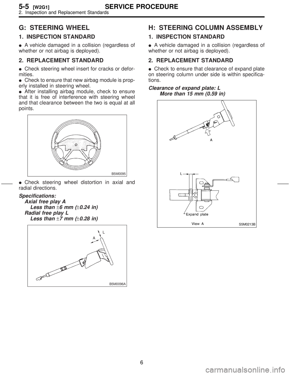
ICheck steering wheel distortion in axial and
radial directions.
Specifications:
Axial free play A
Less than
±6mm(±0.24 in)
Radial free play L
Less than
±7mm(±0.28 in)
B5M0096A
H: STEERING COLUMN ASSEMBLY
1. INSPECTION STANDARD
IA vehicle damaged in a collision (regardless of
whether or not airbag is deployed).
2. REPLACEMENT STANDARD
ICheck to ensure that clearance of expand plate
on steering column under side is within specifica-
tions.
Clearance of expand plate: L
More than 15 mm (0.59 in)
S5M0213B
6
5-5[W2G1]SERVICE PROCEDURE
2. Inspection and Replacement Standards
Page 280 of 345

1. DRIVER'S AIRBAG MODULE
1) Set front wheels in straight ahead position.
2) Turn ignition switch off.
3) Disconnect ground cable from battery and wait
for at least 20 seconds before starting work.
4) Using TORXTBIT T30, remove the two TORXT
bolts.
H5M0662
5) Disconnect airbag connector on back of airbag
module.
H5M0664
6) Refer toªCAUTIONºfor handling of a removed
airbag module.
7) Install in the reverse order of removal.
CAUTION:
Do not allow harness and connectors to inter-
fere or get caught with other parts.
2. PASSENGER'S AIRBAG MODULE
1) Turn ignition switch off.
2) Disconnect ground cable from battery and wait
for at least 20 seconds before starting work.
3) Remove glove box.
4) Disconnect airbag connector.
S5M0214
5) Remove the seven bolts and then carefully
remove airbag module.
S5M0215
6) Refer to ªCAUTIONº for handling of a removed
airbag module.
7) Install in the reverse order of removal.
CAUTION:
Do not allow harness and connectors to inter-
fere or get caught with other parts.
3. SIDE AIRBAG MODULE
The side airbag module cannot be detached from
the front seat assembly. When replacing side air-
bag module, replace front seat assembly.
10
5-5[W3A1]SERVICE PROCEDURE
3. Airbag Module
Page 286 of 345
![SUBARU FORESTER 1999 Service Repair Manual 8. Roll Connector
A: REMOVAL
1) Turn ignition switch off.
2) Disconnect ground cable from battery and wait
for at least 20 seconds before starting work.
3) Remove lower cover. <Ref. to 5-4 [W1A0].>
4) SUBARU FORESTER 1999 Service Repair Manual 8. Roll Connector
A: REMOVAL
1) Turn ignition switch off.
2) Disconnect ground cable from battery and wait
for at least 20 seconds before starting work.
3) Remove lower cover. <Ref. to 5-4 [W1A0].>
4)](/img/17/57427/w960_57427-285.png)
8. Roll Connector
A: REMOVAL
1) Turn ignition switch off.
2) Disconnect ground cable from battery and wait
for at least 20 seconds before starting work.
3) Remove lower cover.
4) Disconnect airbag connector (AB3) and (AB8)
below steering column.
CAUTION:
Do not reconnect airbag connector at steering
column until combination switch is securely re-
installed.
G5M0312
5) Disconnect combination switch connectors
from body harness connector.
6) Set front wheels in straight ahead position.
Using T30 TORXTbit, remove the two TORXT
bolts.
H5M0662
7) Disconnect airbag connector on back of airbag
module.
module, and place it with pad side facing upward.
H5M0664
8) Using steering puller (A), remove steering
wheel.
CAUTION:
Do not allow connector to interfere when
removing steering wheel.
S5M0436A
9) Remove steering column covers.
10) Removing the three retaining screws, remove
combination switch.
S5M0220
14
5-5[W8A0]SERVICE PROCEDURE
8. Roll Connector