SUBARU FORESTER 2004 Service Repair Manual
Manufacturer: SUBARU, Model Year: 2004, Model line: FORESTER, Model: SUBARU FORESTER 2004Pages: 2870, PDF Size: 38.67 MB
Page 1331 of 2870

EN(H4SO)-233
ENGINE (DIAGNOSTIC)
Diagnostic Procedure with Diagnostic Trouble Code (DTC)
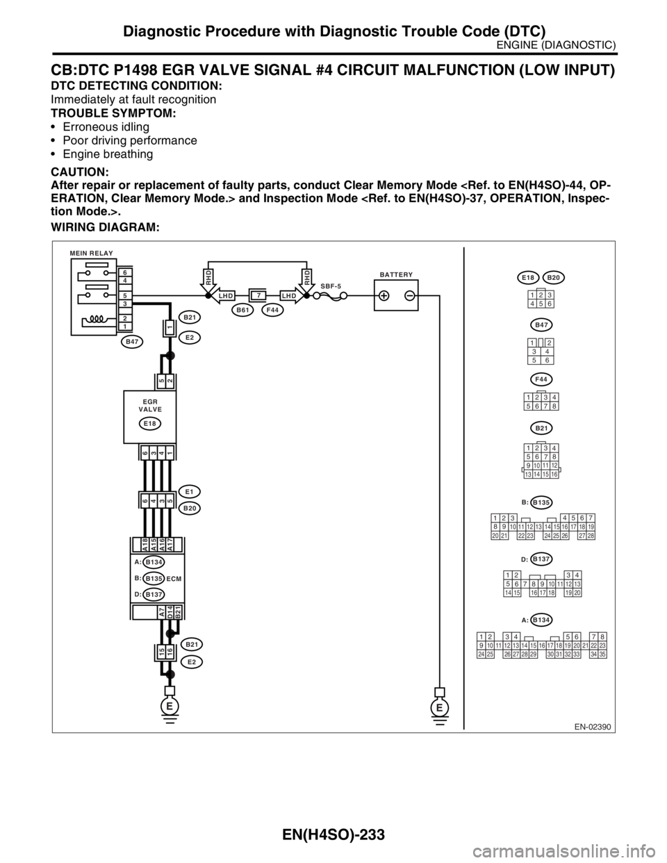
CB:DTC P1498 EGR VALVE SIGNAL #4 CIRCUIT MALFUNCTION (LOW INPUT)
DTC DETECTING CONDITION:
Immediately at fault recognition
TROUBLE SYMPTOM:
Erroneous idling
Poor driving performance
Engine breathing
CAUTION:
After repair or replacement of faulty parts, conduct Clear Memory Mode
WIRING DIAGRAM:
EN-02390
B137
B135
B134
B21
123
4
56
78
9
1011 12
1314 15 16
EE
B47
E18
2 5
1 4 3 6
B21B61F44
E2
B20
E1
B21
E2
6
4
5
3
2
1
1
5 A17 A16 A15 A18
B21 D14A74
3 6
15
16
SBF-5BATTERY MEIN RELAY
EGR
VALVE
A:
B134
B:
B135
D:
B137ECM
B47
F44
E18
3412
56
13
45627
12345678
4
1
53
2618 15 167891011
17 19
20121314
567
82 1
94
310
24 22 23 251112131415
26 27
281617181920 21
1234567891011121314151617181920212223242526272829303132333435
B20
LHDLHD
RHDRHD
A: B:
D:
Page 1332 of 2870

EN(H4SO)-234
ENGINE (DIAGNOSTIC)
Diagnostic Procedure with Diagnostic Trouble Code (DTC)
Step Check Yes No
1 CHECK POWER SUPPLY TO EGR VALVE.
1) Turn the ignition switch to OFF.
2) Disconnect the connector from EGR valve.
3) Turn the ignition switch to ON.
4) Measure the voltage between EGR valve
connector and engine ground.
Connector & terminal
(E18) No. 2 (+) — Engine ground (
−):
(E18) No. 5 (+) — Engine ground (
−):Is the voltage more than 10 V? Go to step 2.Repair harness
and connector.
N
OTE:
In this case repair
the following:
Open circuit in
harness between
EGR valve and
main relay connec-
tor
Poor contact in
coupling connector
2 CHECK HARNESS BETWEEN ECM AND
EGR VALVE CONNECTOR.
1) Turn the ignition switch to OFF.
2) Measure the voltage between ECM and
EGR valve connector.
Connector & terminal
DTC P1492; (B134) No. 18 — (E18) No. 6:
DTC P1494; (B134) No. 17 — (E18) No. 1:
DTC P1496; (B134) No. 16 — (E18) No. 4:
DTC P1498; (B134) No. 15 — (E18) No. 3:Is the resistance less than 1
Ω?Go to step 3.Repair harness
and connector.
N
OTE:
In this case repair
the following:
Open circuit in
harness between
ECM and EGR
valve connector.
Poor contact in
coupling connector
3 CHECK HARNESS BETWEEN ECM AND
EGR VALVE CONNECTOR.
1) Disconnect the connector from ECM.
2) Measure the resistance between ECM con-
nector and chassis ground.
Connector & terminal
DTC P1492; (B134) No. 18 — Chassis
ground:
DTC P1494; (B134) No. 17 — Chassis
ground:
DTC P1496; (B134) No. 16 — Chassis
ground:
DTC P1498; (B134) No. 15 — Chassis
ground:Is the resistance more than 1
MΩ?Go to step 4.Repair ground
short in harness
between ECM and
EGR valve con-
nector.
4 CHECK POOR CONTACT.
Check poor contact in ECM connector and
EGR valve connector.Is there poor contact in ECM
connector or EGR valve con-
nector?Repair poor con-
tact in ECM con-
nector or EGR
valve connector.Replace the EGR
valve.
EGR Valve.>
Page 1333 of 2870

EN(H4SO)-235
ENGINE (DIAGNOSTIC)
Diagnostic Procedure with Diagnostic Trouble Code (DTC)
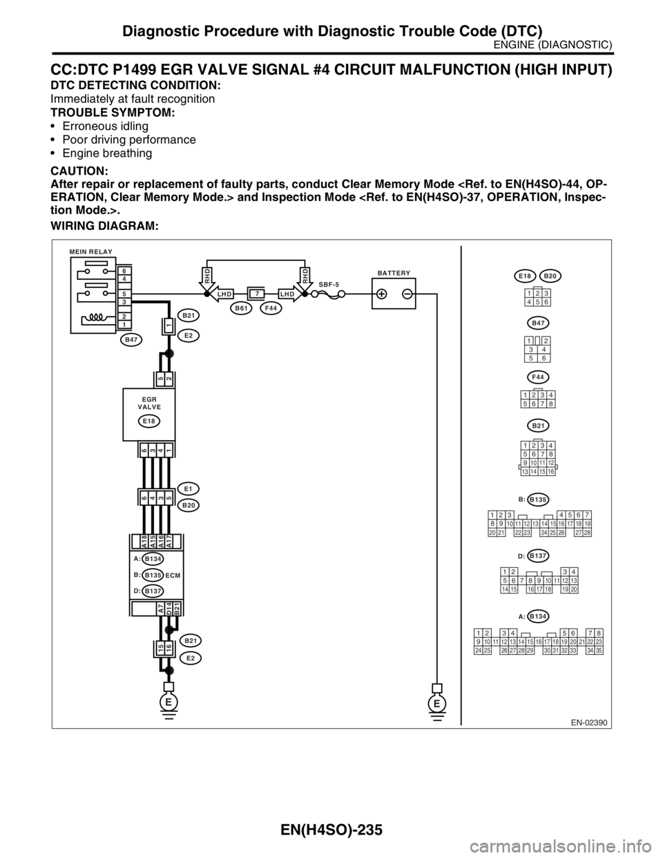
CC:DTC P1499 EGR VALVE SIGNAL #4 CIRCUIT MALFUNCTION (HIGH INPUT)
DTC DETECTING CONDITION:
Immediately at fault recognition
TROUBLE SYMPTOM:
Erroneous idling
Poor driving performance
Engine breathing
CAUTION:
After repair or replacement of faulty parts, conduct Clear Memory Mode
WIRING DIAGRAM:
EN-02390
B137
B135
B134
B21
123
4
56
78
9
1011 12
1314 15 16
EE
B47
E18
2 5
1 4 3 6
B21B61F44
E2
B20
E1
B21
E2
6
4
5
3
2
1
1
5 A17 A16 A15 A18
B21 D14A74
3 6
15
16
SBF-5BATTERY MEIN RELAY
EGR
VALVE
A:
B134
B:
B135
D:
B137ECM
B47
F44
E18
3412
56
13
45627
12345678
4
1
53
2618 15 167891011
17 19
20121314
567
82 1
94
310
24 22 23 251112131415
26 27
281617181920 21
1234567891011121314151617181920212223242526272829303132333435
B20
LHDLHD
RHDRHD
A: B:
D:
Page 1334 of 2870

EN(H4SO)-236
ENGINE (DIAGNOSTIC)
Diagnostic Procedure with Diagnostic Trouble Code (DTC)
Step Check Yes No
1 CHECK ANY OTHER DTC ON DISPLAY.Is any other DTC displayed? Inspect the DTC
using “List of Diag-
nostic Trouble
Code (DTC)”.
of Diagnostic Trou-
ble Code (DTC).>Go to step 2.
2 CHECK GROUND CIRCUIT FOR ECM.
1) Turn the ignition switch to OFF.
2) Measure the resistance between ECM con-
nector and chassis ground.
Connector & terminal
(B134) No. 7 — Chassis ground:
(B135) No. 21 — Chassis ground:
(B137) No. 14 — Chassis ground:Is the resistance less than 5
Ω?Go to step 3.Repair harness
and connector.
N
OTE:
In this case repair
the following:
Open circuit in
harness between
ECM connector
and engine ground
terminal
Poor contact in
ECM connector.
Poor contact in
coupling connector
3 CHECK HARNESS BETWEEN ECM AND
EGR VALVE CONNECTOR.
1) Turn the ignition switch to OFF.
2) Disconnect the connector from EGR valve.
3) Turn the ignition switch to ON.
4) Measure the voltage between ECM con-
nector and chassis ground.
Connector & terminal
DTC P1493; (B134) No. 18 (+) — Chassis
ground (
−):
DTC P1495; (B134) No. 17 (+) — Chassis
ground (
−):
DTC P1497; (B134) No. 16 (+) — Chassis
ground (
−):
DTC P1499; (B134) No. 15 (+) — Chassis
ground (
−):Is the voltage more than 10 V? Repair battery
short in harness
between ECM and
EGR valve con-
nector. After
repair, replace the
ECM.
Engine Control
Module (ECM).>Replace the ECM.
Engine Control
Module (ECM).>
Page 1335 of 2870

EN(H4SO)-237
ENGINE (DIAGNOSTIC)
Diagnostic Procedure with Diagnostic Trouble Code (DTC)
CD:DTC P1510 ISC SOLENOID VALVE SIGNAL #1 CIRCUIT MALFUNCTION
(LOW INPUT)
NOTE:
For the diagnostic procedure, refer to DTC P1516.
Code (DTC).>
CE:DTC P1511 ISC SOLENOID VALVE SIGNAL #1 CIRCUIT MALFUNCTION
(HIGH INPUT)
NOTE:
For the diagnostic procedure, refer to DTC P1517.
Code (DTC).>
CF:DTC P1512 ISC SOLENOID VALVE SIGNAL #2 CIRCUIT MALFUNCTION
(LOW INPUT)
NOTE:
For the diagnostic procedure, refer to DTC P1516.
Code (DTC).>
CG:DTC P1513 ISC SOLENOID VALVE SIGNAL #2 CIRCUIT MALFUNCTION
(HIGH INPUT)
NOTE:
For the diagnostic procedure, refer to DTC P1517.
Code (DTC).>
CH:DTC P1514 ISC SOLENOID VALVE SIGNAL #3 CIRCUIT MALFUNCTION
(LOW INPUT)
NOTE:
For the diagnostic procedure, refer to DTC P1516.
Code (DTC).>
CI: DTC P1515 ISC SOLENOID VALVE SIGNAL #3 CIRCUIT MALFUNCTION
(HIGH INPUT)
NOTE:
For the diagnostic procedure, refer to DTC P1517.
Code (DTC).>
Page 1336 of 2870

EN(H4SO)-238
ENGINE (DIAGNOSTIC)
Diagnostic Procedure with Diagnostic Trouble Code (DTC)
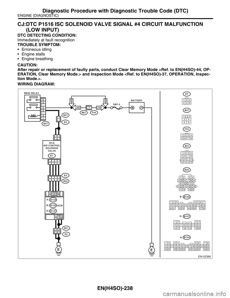
CJ:DTC P1516 ISC SOLENOID VALVE SIGNAL #4 CIRCUIT MALFUNCTION
(LOW INPUT)
DTC DETECTING CONDITION:
Immediately at fault recognition
TROUBLE SYMPTOM:
Erroneous idling
Engine stalls
Engine breathing
CAUTION:
After repair or replacement of faulty parts, conduct Clear Memory Mode
WIRING DIAGRAM:
EN-02396
B137
B135
B134
B21
123
4
56
78
9
1011 12
1314 15 16
EE
B47
E7
2 5
1 4 3 6
B21B61F44
E2
B22
E3
B21
E2
6
4
5
3
2
1
1
2 A6 A20 A19A5
B21 D14A74
1 3
15
16
SBF-5BATTERY MEIN RELAY
IDLE
AIR CONTROL
SOLENOID
VALVE
A:
B134
B:
B135
D:
B137ECM
B47
F44
E7
3412
56
13
4562
B22
125678
131415169101112
34
17181920
7
12345678
4
1
53
2618 15 167891011
17 19
20121314
567
82 1
94
310
24 22 23 251112131415
26 27
281617181920 21
1234567891011121314151617181920212223242526272829303132333435
LHDLHD
RHDRHD
A: B:
D:
Page 1337 of 2870

EN(H4SO)-239
ENGINE (DIAGNOSTIC)
Diagnostic Procedure with Diagnostic Trouble Code (DTC)
Step Check Yes No
1 CHECK POWER SUPPLY TO IDLE AIR CON-
TROL SOLENOID VALVE.
1) Turn the ignition switch to OFF.
2) Disconnect the connector from idle air con-
trol solenoid valve.
3) Turn the ignition switch to ON.
4) Measure the voltage between idle air con-
trol solenoid valve connector and engine
ground.
Connector & terminal
(E7) No. 2 (+) — Engine ground (
−):
(E7) No. 5 (+) — Engine ground (
−):Is the voltage more than 10 V? Go to step 2.Repair harness
and connector.
N
OTE:
In this case repair
the following:
Open circuit in
harness between
idle air control
solenoid valve and
main relay connec-
tor
Poor contact in
coupling connector
2 CHECK HARNESS BETWEEN ECM AND
IDLE AIR CONTROL SOLENOID VALVE
CONNECTOR.
1) Turn the ignition switch to OFF.
2) Measure the resistance between ECM and
idle air control solenoid valve connector.
Connector & terminal
DTC P1510; (B134) No. 20 — (E7) No. 4:
DTC P1512; (B134) No. 6 — (E7) No. 1:
DTC P1514; (B134) No. 5 — (E7) No. 6:
DTC P1516; (B134) No. 19 — (E7) No. 3:Is the resistance less than 1
Ω?Go to step 3.Repair harness
and connector.
N
OTE:
In this case repair
the following:
Open circuit in
harness between
ECM and idle air
control solenoid
valve connector
Poor contact in
coupling connector
3 CHECK HARNESS BETWEEN ECM AND
IDLE AIR CONTROL SOLENOID VALVE
CONNECTOR.
1) Disconnect the connector from ECM.
2) Measure the resistance between ECM con-
nector and chassis ground.
Connector & terminal
DTC P1510; (B134) No. 20 — Chassis
ground:
DTC P1512; (B134) No. 6 — Chassis
ground:
DTC P1514; (B134) No. 5 — Chassis
ground:
DTC P1516; (B134) No. 19 — Chassis
ground:Is the resistance more than 1
MΩ?Go to step 4.Repair ground
short circuit in har-
ness between
ECM and idle air
control solenoid
valve connector.
4 CHECK POOR CONTACT.
Check poor contact in ECM connector and idle
air control solenoid valve connector.Is there poor contact in ECM
connector or idle air control
solenoid valve connector?Repair the poor
contact in ECM
connector or idle
air control solenoid
valve connector.Replace the idle
air control solenoid
valve.
Air Control Sole-
noid Valve.>
Page 1338 of 2870

EN(H4SO)-240
ENGINE (DIAGNOSTIC)
Diagnostic Procedure with Diagnostic Trouble Code (DTC)
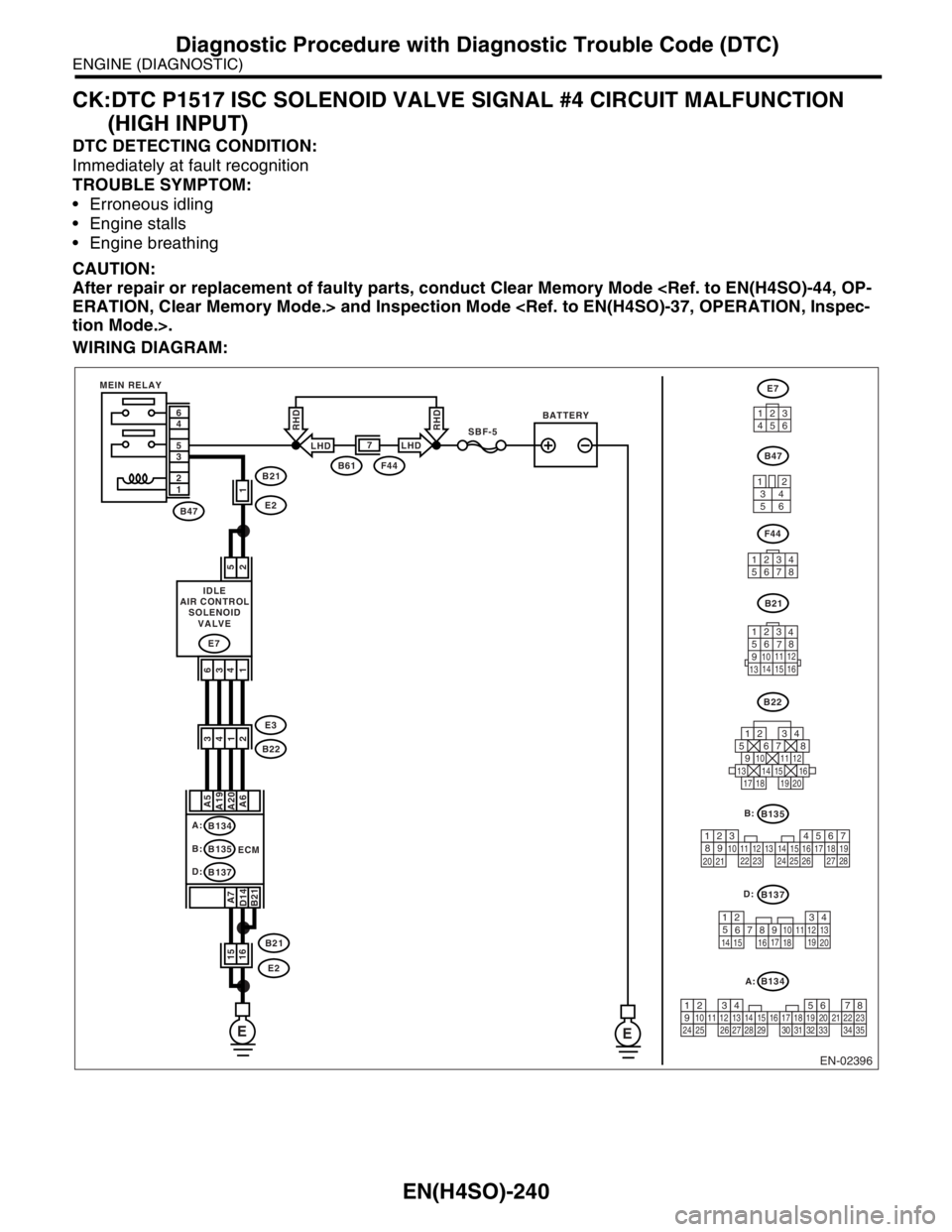
CK:DTC P1517 ISC SOLENOID VALVE SIGNAL #4 CIRCUIT MALFUNCTION
(HIGH INPUT)
DTC DETECTING CONDITION:
Immediately at fault recognition
TROUBLE SYMPTOM:
Erroneous idling
Engine stalls
Engine breathing
CAUTION:
After repair or replacement of faulty parts, conduct Clear Memory Mode
WIRING DIAGRAM:
EN-02396
B137
B135
B134
B21
123
4
56
78
9
1011 12
1314 15 16
EE
B47
E7
2 5
1 4 3 6
B21B61F44
E2
B22
E3
B21
E2
6
4
5
3
2
1
1
2 A6 A20 A19A5
B21 D14A74
1 3
15
16
SBF-5BATTERY MEIN RELAY
IDLE
AIR CONTROL
SOLENOID
VALVE
A:
B134
B:
B135
D:
B137ECM
B47
F44
E7
3412
56
13
4562
B22
125678
131415169101112
34
17181920
7
12345678
4
1
53
2618 15 167891011
17 19
20121314
567
82 1
94
310
24 22 23 251112131415
26 27
281617181920 21
1234567891011121314151617181920212223242526272829303132333435
LHDLHD
RHDRHD
A: B:
D:
Page 1339 of 2870

EN(H4SO)-241
ENGINE (DIAGNOSTIC)
Diagnostic Procedure with Diagnostic Trouble Code (DTC)
Step Check Yes No
1 CHECK ANY OTHER DTC ON DISPLAY.Is any other DTC displayed? Inspect the DTC
using “List of Diag-
nostic Trouble
Code (DTC)”.
of Diagnostic Trou-
ble Code (DTC).>Go to step 2.
2 CHECK GROUND CIRCUIT FOR ECM.
1) Turn the ignition switch to OFF.
2) Measure the resistance between ECM con-
nector and chassis ground.
Connector & terminal
(B134) No. 7 — Chassis ground:
(B135) No. 21 — Chassis ground:
(B137) No. 14 — Chassis ground:Is the resistance less than 5
Ω?Go to step 3.Repair harness
and connector.
N
OTE:
In this case repair
the following:
Open circuit in
harness between
ECM connector
and engine ground
terminal
Poor contact in
ECM connector.
Poor contact in
coupling connector
3 CHECK HARNESS BETWEEN ECM AND
IDLE AIR CONTROL SOLENOID VALVE
CONNECTOR.
1) Turn the ignition switch to OFF.
2) Disconnect the connector from idle air con-
trol solenoid valve.
3) Turn the ignition switch to ON.
4) Measure the voltage between ECM con-
nector and chassis ground.
Connector & terminal
DTC P1511; (B134) No. 20 (+) — Chassis
ground (
−):
DTC P1513; (B134) No. 6 (+) — Chassis
ground (
−):
DTC P1515; (B134) No. 5 (+) — Chassis
ground (
−):
DTC P1517; (B134) No. 19 (+) — Chassis
ground (
−):Is the voltage more than 10 V? Repair battery
short circuit in har-
ness between
ECM and idle air
control solenoid
valve connector.
After repair,
replace the ECM.
Engine Control
Module (ECM).>Replace the ECM.
Engine Control
Module (ECM).>
Page 1340 of 2870

EN(H4SO)-242
ENGINE (DIAGNOSTIC)
Diagnostic Procedure with Diagnostic Trouble Code (DTC)
CL:DTC P1518 STARTER SWITCH CIRCUIT LOW INPUT
DTC DETECTING CONDITION:
Two consecutive driving cycles with fault
TROUBLE SYMPTOM:
Failure of engine to start
CAUTION:
After repair or replacement of faulty parts, conduct Clear Memory Mode