SUBARU FORESTER 2004 Service Repair Manual
Manufacturer: SUBARU, Model Year: 2004, Model line: FORESTER, Model: SUBARU FORESTER 2004Pages: 2870, PDF Size: 38.67 MB
Page 2861 of 2870
CL-35
CLUTCH SYSTEM
Clutch Pedal
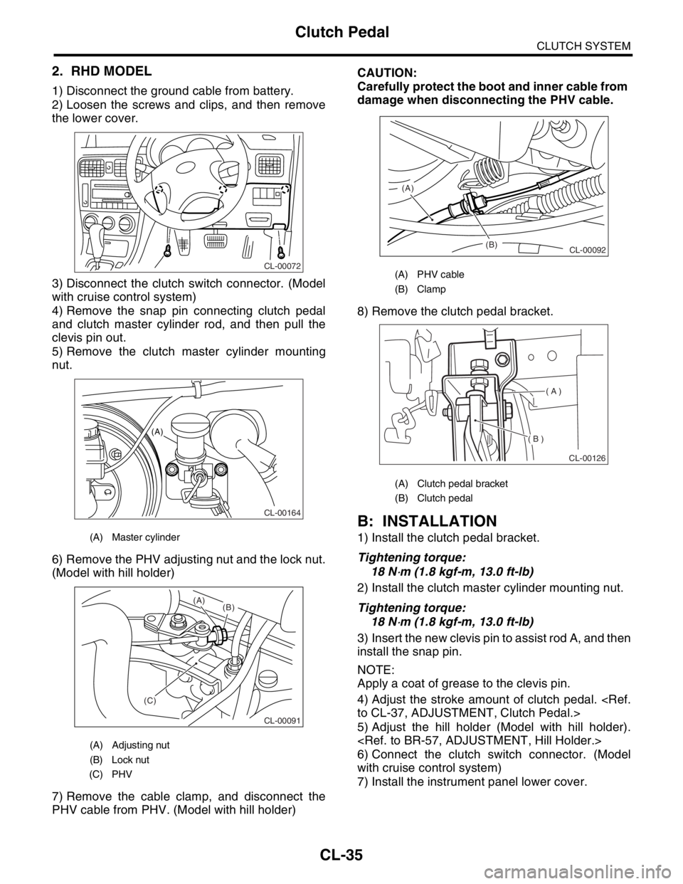
2. RHD MODEL
1) Disconnect the ground cable from battery.
2) Loosen the screws and clips, and then remove
the lower cover.
3) Disconnect the clutch switch connector. (Model
with cruise control system)
4) Remove the snap pin connecting clutch pedal
and clutch master cylinder rod, and then pull the
clevis pin out.
5) Remove the clutch master cylinder mounting
nut.
6) Remove the PHV adjusting nut and the lock nut.
(Model with hill holder)
7) Remove the cable clamp, and disconnect the
PHV cable from PHV. (Model with hill holder)CAUTION:
Carefully protect the boot and inner cable from
damage when disconnecting the PHV cable.
8) Remove the clutch pedal bracket.
B: INSTALLATION
1) Install the clutch pedal bracket.
Tightening torque:
18 N
⋅m (1.8 kgf-m, 13.0 ft-lb)
2) Install the clutch master cylinder mounting nut.
Tightening torque:
18 N
⋅m (1.8 kgf-m, 13.0 ft-lb)
3) Insert the new clevis pin to assist rod A, and then
install the snap pin.
NOTE:
Apply a coat of grease to the clevis pin.
4) Adjust the stroke amount of clutch pedal.
5) Adjust the hill holder (Model with hill holder).
6) Connect the clutch switch connector. (Model
with cruise control system)
7) Install the instrument panel lower cover.
(A) Master cylinder
(A) Adjusting nut
(B) Lock nut
(C) PHV
CL-00072
CL-00164
(A)
CL-00091
(C)(B) (A)
(A) PHV cable
(B) Clamp
(A) Clutch pedal bracket
(B) Clutch pedal
(B) (A)
CL-00092
( A )
( B )
CL-00126
Page 2862 of 2870
CL-36
CLUTCH SYSTEM
Clutch Pedal
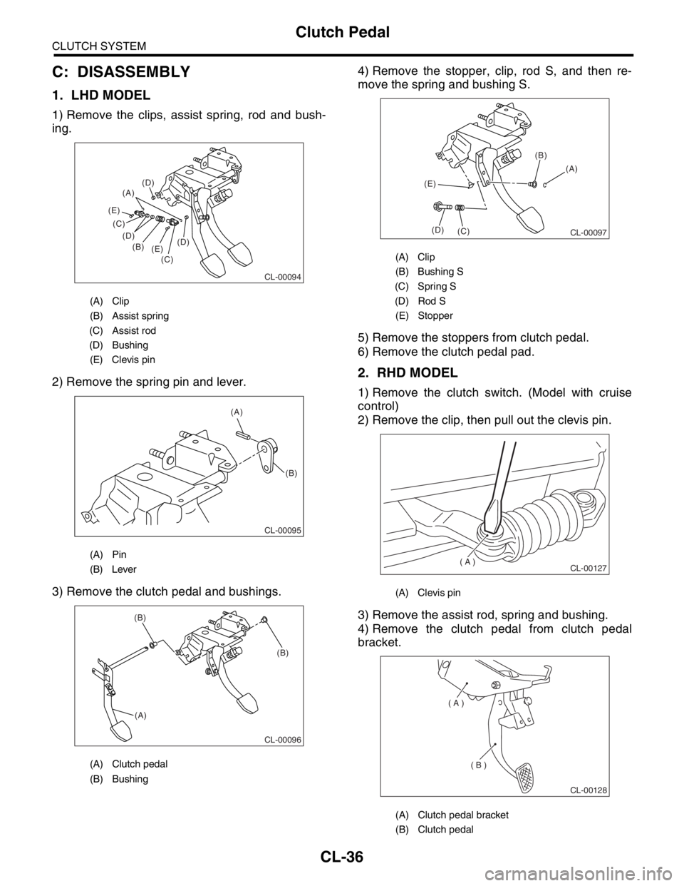
C: DISASSEMBLY
1. LHD MODEL
1) Remove the clips, assist spring, rod and bush-
ing.
2) Remove the spring pin and lever.
3) Remove the clutch pedal and bushings.4) Remove the stopper, clip, rod S, and then re-
move the spring and bushing S.
5) Remove the stoppers from clutch pedal.
6) Remove the clutch pedal pad.
2. RHD MODEL
1) Remove the clutch switch. (Model with cruise
control)
2) Remove the clip, then pull out the clevis pin.
3) Remove the assist rod, spring and bushing.
4) Remove the clutch pedal from clutch pedal
bracket.
(A) Clip
(B) Assist spring
(C) Assist rod
(D) Bushing
(E) Clevis pin
(A) Pin
(B) Lever
(A) Clutch pedal
(B) Bushing
CL-00094
(A)
(B)
(C) (C)
(D) (D)
(D)
(E) (E)
(A)
(B)
CL-00095
CL-00096
(A)(B) (B)
(A) Clip
(B) Bushing S
(C) Spring S
(D) Rod S
(E) Stopper
(A) Clevis pin
(A) Clutch pedal bracket
(B) Clutch pedal
CL-00097
(A) (B)
(C) (D) (E)
( A )
CL-00127
( A )
( B )
CL-00128
Page 2863 of 2870
CL-37
CLUTCH SYSTEM
Clutch Pedal
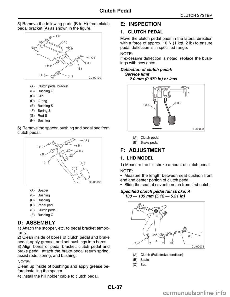
5) Remove the following parts (B to H) from clutch
pedal bracket (A) as shown in the figure.
6) Remove the spacer, bushing and pedal pad from
clutch pedal.
D: ASSEMBLY
1) Attach the stopper, etc. to pedal bracket tempo-
rarily.
2) Clean inside of bores of clutch pedal and brake
pedal, apply grease, and set bushings into bores.
3) Align bores of pedal bracket, clutch pedal and
brake pedal, attach the brake pedal return spring,
assist rods, spring, and bushing.
NOTE:
Clean up inside of bushings and apply grease be-
fore installing the spacer.
4) Install the hill holder cable to clutch pedal.
E: INSPECTION
1. CLUTCH PEDAL
Move the clutch pedal pads in the lateral direction
with a force of approx. 10 N (1 kgf, 2 lb) to ensure
pedal deflection is in specified range.
NOTE:
If excessive deflection is noted, replace the bush-
ings with new ones.
Deflection of clutch pedal:
Service limit
2.0 mm (0.079 in) or less
F: ADJUSTMENT
1. LHD MODEL
1) Measure the full stroke amount of clutch pedal.
NOTE:
Measure the length between seat cushion front
end and center portion of clutch pedal.
Slide the seat at seventh notch from first notch.
Specified clutch pedal full stroke: A
130 — 135 mm (5.12 — 5.31 in)
(A) Clutch pedal bracket
(B) Bushing C
(C) Clip
(D) O-ring
(E) Bushing S
(F) Spring S
(G) Rod S
(H) Bushing
(A) Spacer
(B) Bushing
(C) Bushing
(D) Pedal pad
(E) Clutch pedal
(F) Bushing C
( A )
( B )
( C )
( D )
( E )
( F )( G )
( H )
CL-00129
( A )
( B )
( B )
( C )
( D )
( E )
( F )
( F )
CL-00130
(A) Clutch pedal
(B) Brake pedal
(A) Clutch (Full stroke condition)
(B) Scale
(C) Seat
CL-00098
CL-00078(A)(B)(C)A
Page 2864 of 2870
CL-38
CLUTCH SYSTEM
Clutch Pedal
2) If not as specified, loosen the clutch stopper nut
to adjust it.
Tightening torque (Clutch stopper nut):
8 N
⋅m (0.8 kgf-m, 5.8 ft-lb)
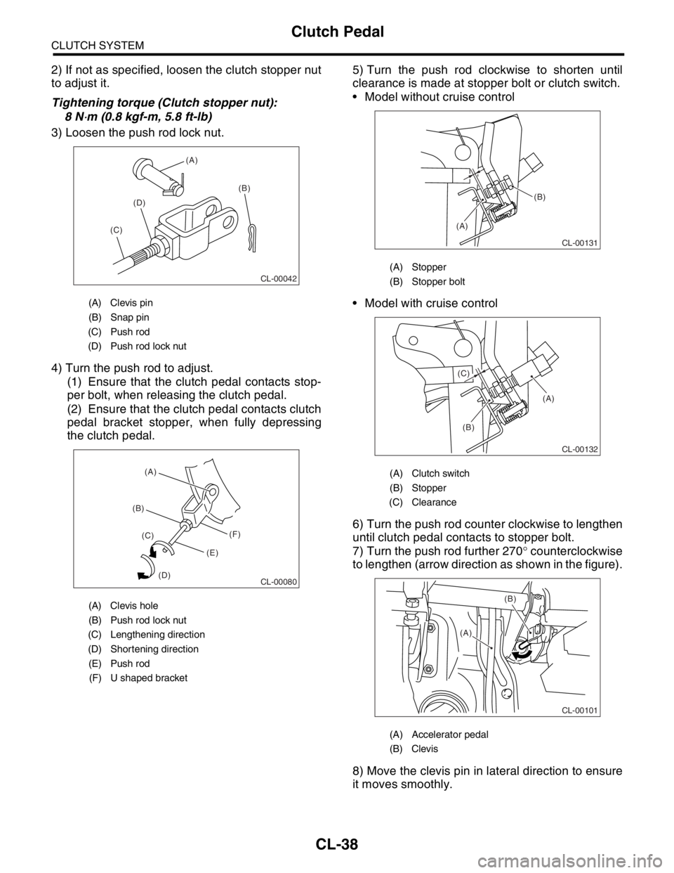
3) Loosen the push rod lock nut.
4) Turn the push rod to adjust.
(1) Ensure that the clutch pedal contacts stop-
per bolt, when releasing the clutch pedal.
(2) Ensure that the clutch pedal contacts clutch
pedal bracket stopper, when fully depressing
the clutch pedal.5) Turn the push rod clockwise to shorten until
clearance is made at stopper bolt or clutch switch.
Model without cruise control
Model with cruise control
6) Turn the push rod counter clockwise to lengthen
until clutch pedal contacts to stopper bolt.
7) Turn the push rod further 270° counterclockwise
to lengthen (arrow direction as shown in the figure).
8) Move the clevis pin in lateral direction to ensure
it moves smoothly.
(A) Clevis pin
(B) Snap pin
(C) Push rod
(D) Push rod lock nut
(A) Clevis hole
(B) Push rod lock nut
(C) Lengthening direction
(D) Shortening direction
(E) Push rod
(F) U shaped bracket
CL-00042
(A)
(B)
(C)(D)
CL-00080
(B)(A)
(C)
(D)(E)(F)
(A) Stopper
(B) Stopper bolt
(A) Clutch switch
(B) Stopper
(C) Clearance
(A) Accelerator pedal
(B) Clevis
(A)
(B)
CL-00131
(A)
(B) (C)
CL-00132
CL-00101
(B)
(A)
Page 2865 of 2870
CL-39
CLUTCH SYSTEM
Clutch Pedal
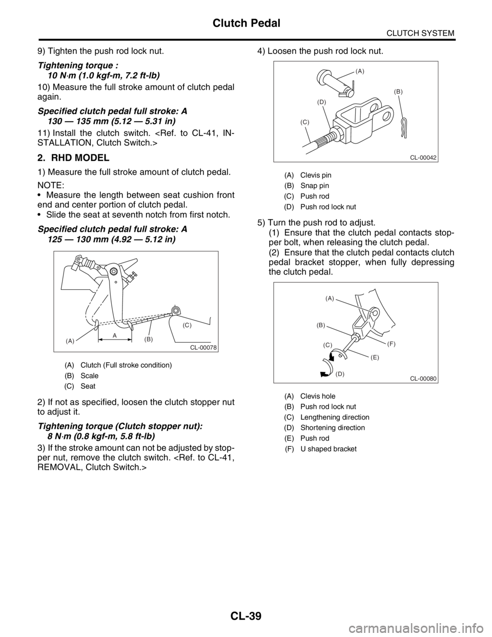
9) Tighten the push rod lock nut.
Tightening torque :
10 N
⋅m (1.0 kgf-m, 7.2 ft-lb)
10) Measure the full stroke amount of clutch pedal
again.
Specified clutch pedal full stroke: A
130 — 135 mm (5.12 — 5.31 in)
11) Install the clutch switch.
2. RHD MODEL
1) Measure the full stroke amount of clutch pedal.
NOTE:
Measure the length between seat cushion front
end and center portion of clutch pedal.
Slide the seat at seventh notch from first notch.
Specified clutch pedal full stroke: A
125 — 130 mm (4.92 — 5.12 in)
2) If not as specified, loosen the clutch stopper nut
to adjust it.
Tightening torque (Clutch stopper nut):
8 N
⋅m (0.8 kgf-m, 5.8 ft-lb)
3) If the stroke amount can not be adjusted by stop-
per nut, remove the clutch switch.
5) Turn the push rod to adjust.
(1) Ensure that the clutch pedal contacts stop-
per bolt, when releasing the clutch pedal.
(2) Ensure that the clutch pedal contacts clutch
pedal bracket stopper, when fully depressing
the clutch pedal.
(A) Clutch (Full stroke condition)
(B) Scale
(C) Seat
CL-00078(A)(B)(C)A
(A) Clevis pin
(B) Snap pin
(C) Push rod
(D) Push rod lock nut
(A) Clevis hole
(B) Push rod lock nut
(C) Lengthening direction
(D) Shortening direction
(E) Push rod
(F) U shaped bracket
CL-00042
(A)
(B)
(C)(D)
CL-00080
(B)(A)
(C)
(D)(E)(F)
Page 2866 of 2870
CL-40
CLUTCH SYSTEM
Clutch Pedal
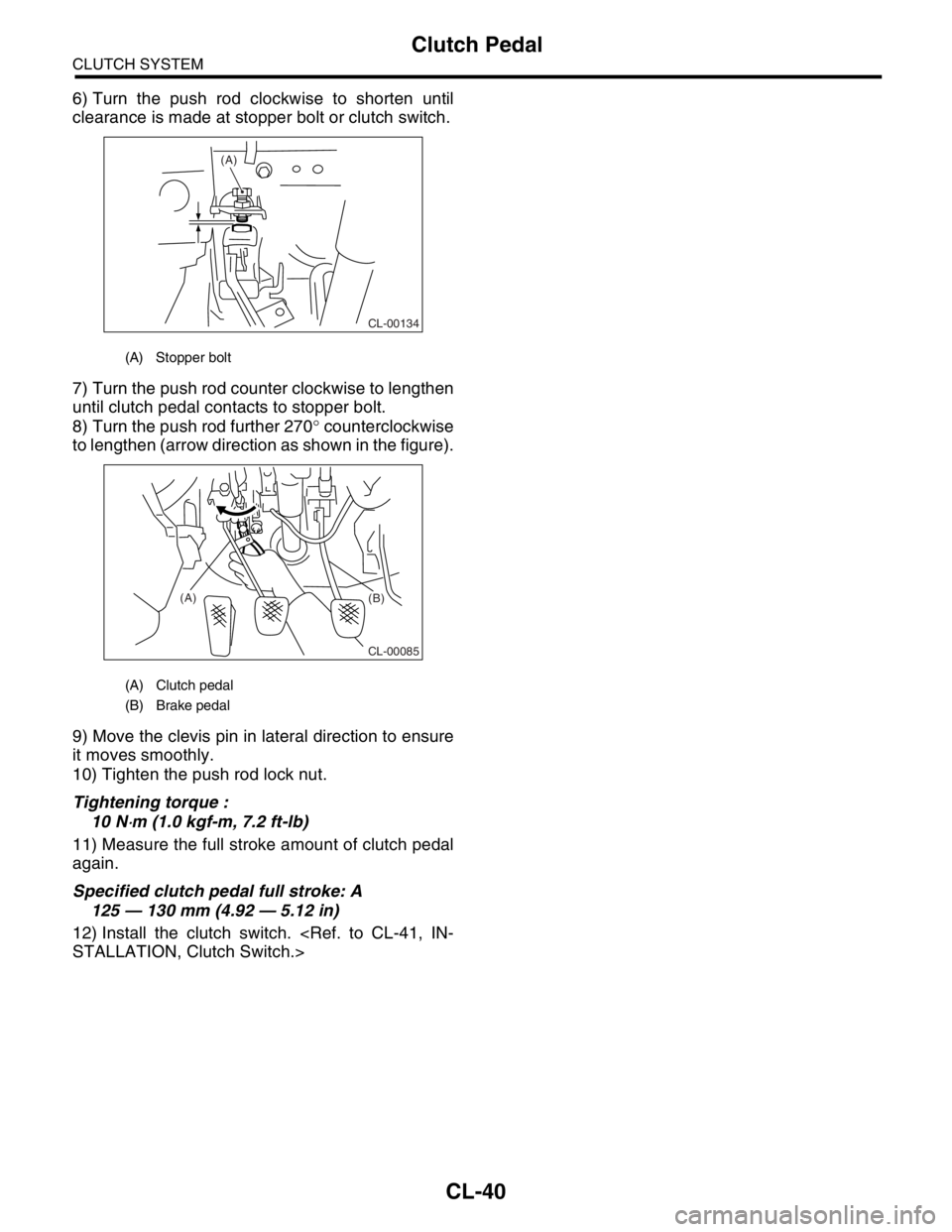
6) Turn the push rod clockwise to shorten until
clearance is made at stopper bolt or clutch switch.
7) Turn the push rod counter clockwise to lengthen
until clutch pedal contacts to stopper bolt.
8) Turn the push rod further 270° counterclockwise
to lengthen (arrow direction as shown in the figure).
9) Move the clevis pin in lateral direction to ensure
it moves smoothly.
10) Tighten the push rod lock nut.
Tightening torque :
10 N
⋅m (1.0 kgf-m, 7.2 ft-lb)
11) Measure the full stroke amount of clutch pedal
again.
Specified clutch pedal full stroke: A
125 — 130 mm (4.92 — 5.12 in)
12) Install the clutch switch.
(A) Stopper bolt
(A) Clutch pedal
(B) Brake pedal
CL-00134
(A)
CL-00085
(A)
(B)
Page 2867 of 2870
CL-41
CLUTCH SYSTEM
Clutch Switch
11.Clutch Switch
A: REMOVAL
1) Disconnect the ground cable from battery.
2) Remove the instrument panel lower cover.
3) Disconnect the connector from clutch switch.
4) Remove the clutch switch.
B: INSTALLATION
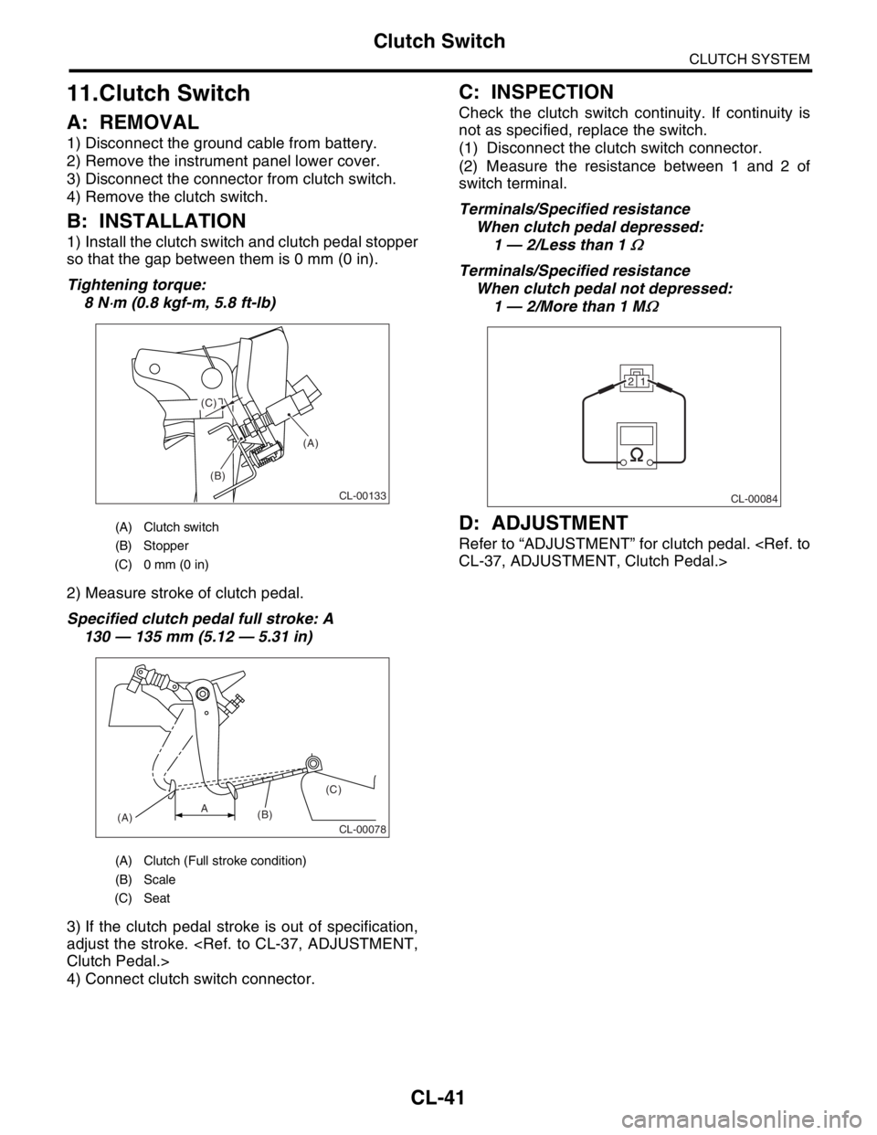
1) Install the clutch switch and clutch pedal stopper
so that the gap between them is 0 mm (0 in).
Tightening torque:
8 N
⋅m (0.8 kgf-m, 5.8 ft-lb)
2) Measure stroke of clutch pedal.
Specified clutch pedal full stroke: A
130 — 135 mm (5.12 — 5.31 in)
3) If the clutch pedal stroke is out of specification,
adjust the stroke.
4) Connect clutch switch connector.
C: INSPECTION
Check the clutch switch continuity. If continuity is
not as specified, replace the switch.
(1) Disconnect the clutch switch connector.
(2) Measure the resistance between 1 and 2 of
switch terminal.
Terminals/Specified resistance
When clutch pedal depressed:
1 — 2/Less than 1
Ω
Terminals/Specified resistance
When clutch pedal not depressed:
1 — 2/More than 1 M
Ω
D: ADJUSTMENT
Refer to “ADJUSTMENT” for clutch pedal.
(A) Clutch switch
(B) Stopper
(C) 0 mm (0 in)
(A) Clutch (Full stroke condition)
(B) Scale
(C) Seat
(A)
(B) (C)
CL-00133
CL-00078(A)(B)(C)A
CL-00084
21
Page 2868 of 2870

CL-42
CLUTCH SYSTEM
General Diagnostic Table
12.General Diagnostic Table
A: INSPECTION
1. CLUTCH
Symptom Possible cause Corrective
1. Clutch slippage.
It is hard to perceive clutch slippage in
the early stage, but pay attention to the
following symptoms
Engine speed up when shifting.
High speed driving is impossible; espe-
cially rapid acceleration impossible and
vehicle speed does not increase in pro-
portion to an increase in engine speed.
Power falls, particularly when ascend-
ing a slope, and there is a smell of burn-
ing of the clutch facing.
Method of testing: Put the vehicle in
stationary condition with parking brake
fully applied. Disengage the clutch and
shift the transmission gear into the first.
Gradually allow the clutch to engage
while gradually increasing the engine
speed. The clutch function is satisfactory
if the engine stalls. However, the clutch is
slipping if the vehicle does not start off
and the engine does not stall.(a) Clutch facing smeared by oil Replace.
(b) Worn clutch facing Replace.
(c) Deteriorated diaphragm spring Replace.
(d) Distorted pressure plate or flywheel Replace.
(e) Defective release bearing holder Replace.
2. Clutch drags.
As a symptom of this trouble, a harsh
scratching noise develops and control
becomes quite difficult when shifting
gears. The symptom becomes more
apparent when shifting into the first gear.
However, because much trouble of this
sort is due to defective synchronization
mechanism, carry out the test as
described after.
Method of testing:
DRAG, INSPECTION, General Diagnos-
tic Table.>
It may be judged as insufficient disen-
gagement of clutch if any noise occurs
during this test.(a) Worn or rusty clutch disc hub spline Replace the clutch disc.
(b) Excessive deflection of clutch disc
facingReplace.
(c) Malfunction of crankshaft pilot bearing Replace.
(d) Cracked clutch disc facing Replace.
(e) Stuck clutch disc (smeared by oil or
water)Replace.
3. Clutch chatters.
Clutch chattering is an unpleasant vibra-
tion to the whole body when the vehicle is
just started with clutch partially engaged.(a) Adhesion of oil on the facing Replace the clutch disc.
(b) Weak or broken torsion spring Replace the clutch disc.
(c) Defective facing contact or excessive
disc wornReplace the clutch disc defection.
(d) Warped pressure plate or flywheel Replace.
(e) Loose disc rivets Replace the clutch disc.
(f) Loose engine mounting Retighten or replace the mounting.
(g) Improper adjustment of pitching stop-
perAdjustment.
Page 2869 of 2870

CL-43
CLUTCH SYSTEM
General Diagnostic Table
2. CLUTCH PEDAL
3. DIAGNOSTIC DIAGRAM OF CLUTCH DRAG
4. Noisy clutch
Examine whether the noise is generated
when the clutch is disengaged, engaged,
or partially engaged.(a) Broken, worn or unlubricated release
bearingReplace the release bearing.
(b) Insufficient lubrication of pilot bearing Replace.
(c) Loose clutch disc hub Replace the clutch disc.
(d) Loose torsion spring retainer Replace the clutch disc.
(e) Deteriorated or broken torsion spring Replace the clutch disc.
5. Clutch grabs.
When starting the vehicle with the clutch
partially engaged, the clutch engages
suddenly and the vehicle jumps instead
of making a smooth start.(a) Grease or oil on facing Replace the clutch disc.
(b) Deteriorated cushioning spring Replace the clutch disc.
(c) Worn or rusted spline of clutch disc or
main shaftTake off rust, apply grease or replace the
clutch disc or main shaft.
(d) Deteriorated or broken torsion spring Replace the clutch disc.
(e) Loose engine mounting Retighten or replace the mounting.
(f) Deteriorated diaphragm spring Replace.
Trouble Corrective action
Insufficient pedal play Adjust pedal play.
Clutch pedal free play insufficient Adjust pedal free play.
Excessively worn and damaged pedal shaft and/or bushing Replace the bushing and/or shaft with a new one.
Step Check Yes No
1 CHECK GEAR NOISE.
1) Start the engine.
2) Disengage the clutch and shift quickly from
neutral to reverse in idling condition.Is there any abnormal noise
from the transmission gear?Go to step 2.Clutch is normal.
2 CHECK GEAR NOISE.
Disengage the clutch at idle and shift from neu-
tral to reverse within 0.5 — 1.0 seconds.Is there any abnormal noise
from the transmission gear?Go to step 3.Defective trans-
mission or exces-
sive clutch drag
torque. Inspect the
pilot bearing,
clutch disc, trans-
mission and clutch
disc hub spline.
3 CHECK GEAR NOISE.
1) Disengage the clutch at idle and shift from
neutral to reverse within 0.5 — 1.0 seconds.
2) With the clutch disengaged, shift from N to
R, R to N several times.Is there any abnormal noise
from the transmission gear?Defect in clutch
disengaging.
Inspect the clutch
disc, clutch cover,
clutch release, and
clutch pedal free
play.Clutch and fly-
wheel seizure.
Inspect the clutch
disc, spline of
clutch disc hub. Symptom Possible cause Corrective
Page 2870 of 2870

CL-44
CLUTCH SYSTEM
General Diagnostic Table