replace SUBARU FORESTER 2004 Service Repair Manual
[x] Cancel search | Manufacturer: SUBARU, Model Year: 2004, Model line: FORESTER, Model: SUBARU FORESTER 2004Pages: 2870, PDF Size: 38.67 MB
Page 398 of 2870
IDI-14
INSTRUMENTATION/DRIVER INFO
Tachometer
5. Tachometer
A: REMOVAL
Disassemble the combination meter, and then re-
move the tachometer.
B: INSTALLATION
Install in the reverse order of removal.
C: INSPECTION
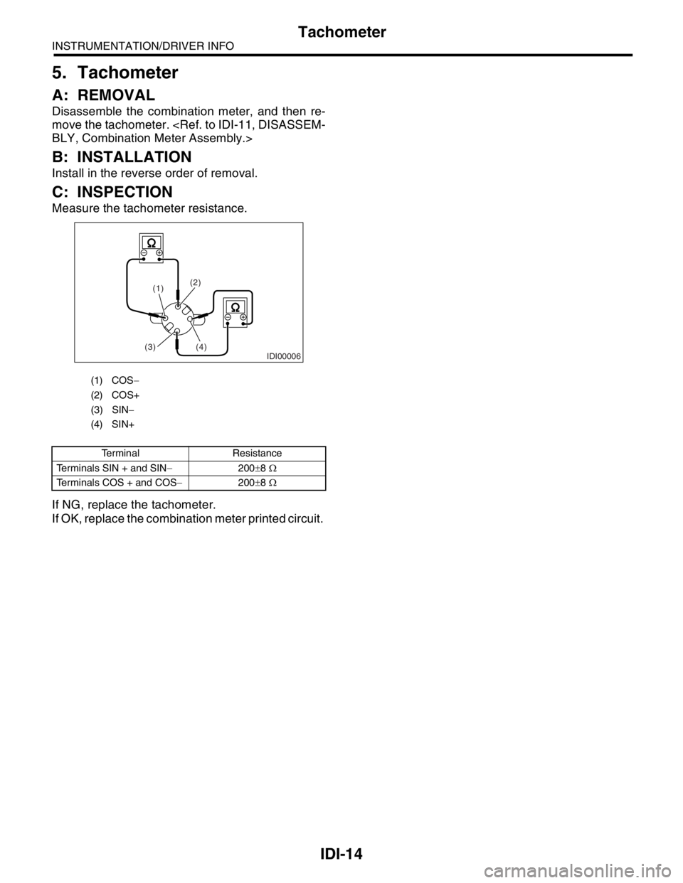
Measure the tachometer resistance.
If NG, replace the tachometer.
If OK, replace the combination meter printed circuit.
(1) COS−
(2) COS+
(3) SIN−
(4) SIN+
Terminal Resistance
Terminals SIN + and SIN−200±8 Ω
Terminals COS + and COS−200±8 Ω
IDI00006
(1)(2)
(4)
(3)
Page 399 of 2870
IDI-15
INSTRUMENTATION/DRIVER INFO
Fuel Gauge
6. Fuel Gauge
A: REMOVAL
Disassemble the combination meter, and then remove
the water temperature gauge and fuel gauge assem-
bly.
B: INSTALLATION
Install in the reverse order of removal.
C: INSPECTION
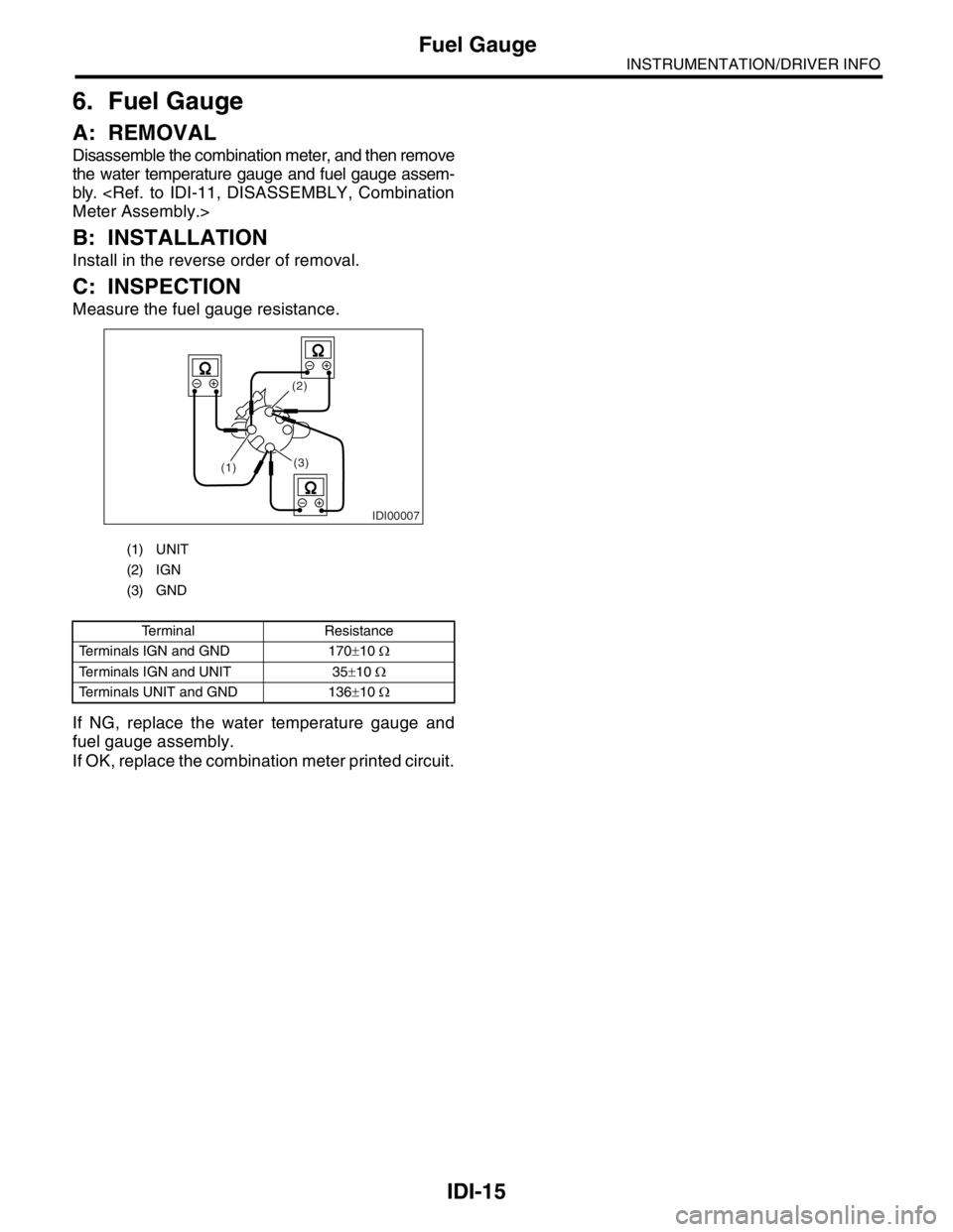
Measure the fuel gauge resistance.
If NG, replace the water temperature gauge and
fuel gauge assembly.
If OK, replace the combination meter printed circuit.
(1) UNIT
(2) IGN
(3) GND
Terminal Resistance
Terminals IGN and GND 170±10 Ω
Terminals IGN and UNIT 35±10 Ω
Terminals UNIT and GND 136±10 Ω
IDI00007
(3) (2)
(1)
Page 400 of 2870
IDI-16
INSTRUMENTATION/DRIVER INFO
Water Temperature Gauge
7. Water Temperature Gauge
A: REMOVAL
Disassemble the combination meter, and then remove
the water temperature gauge and fuel gauge assem-
bly.
B: INSTALLATION
Install in the reverse order of removal.
C: INSPECTION
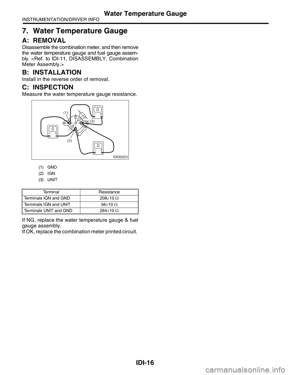
Measure the water temperature gauge resistance.
If NG, replace the water temperature gauge & fuel
gauge assembly.
If OK, replace the combination meter printed circuit.
(1) GND
(2) IGN
(3) UNIT
Terminal Resistance
Terminals IGN and GND 208±10 Ω
Terminals IGN and UNIT 56±10 Ω
Terminals UNIT and GND 264±10 Ω
IDI00023
(1)
(2)(3)
Page 401 of 2870

IDI-17
INSTRUMENTATION/DRIVER INFO
Ambient Sensor
8. Ambient Sensor
A: REMOVAL
1) Disconnect the ground cable from battery.
2) Disconnect the ambient sensor connector.
3) Remove the ambient sensor (A) from radiator lower
panel.
B: INSTALLATION
Install in the reverse order of removal.
C: INSPECTION
Measure the ambient sensor resistance.
If NG, replace the ambient sensor.
Terminal Resistance
1 and 2 3 kΩ/25°C (77°F)
IDI00008
(A)
IDI-00009
21
Page 403 of 2870
FUJI HEAVY INDUSTRIES LTD. G8080GE7
2004 FORESTER SERVICE MANUAL QUICK REFERENCE INDEX
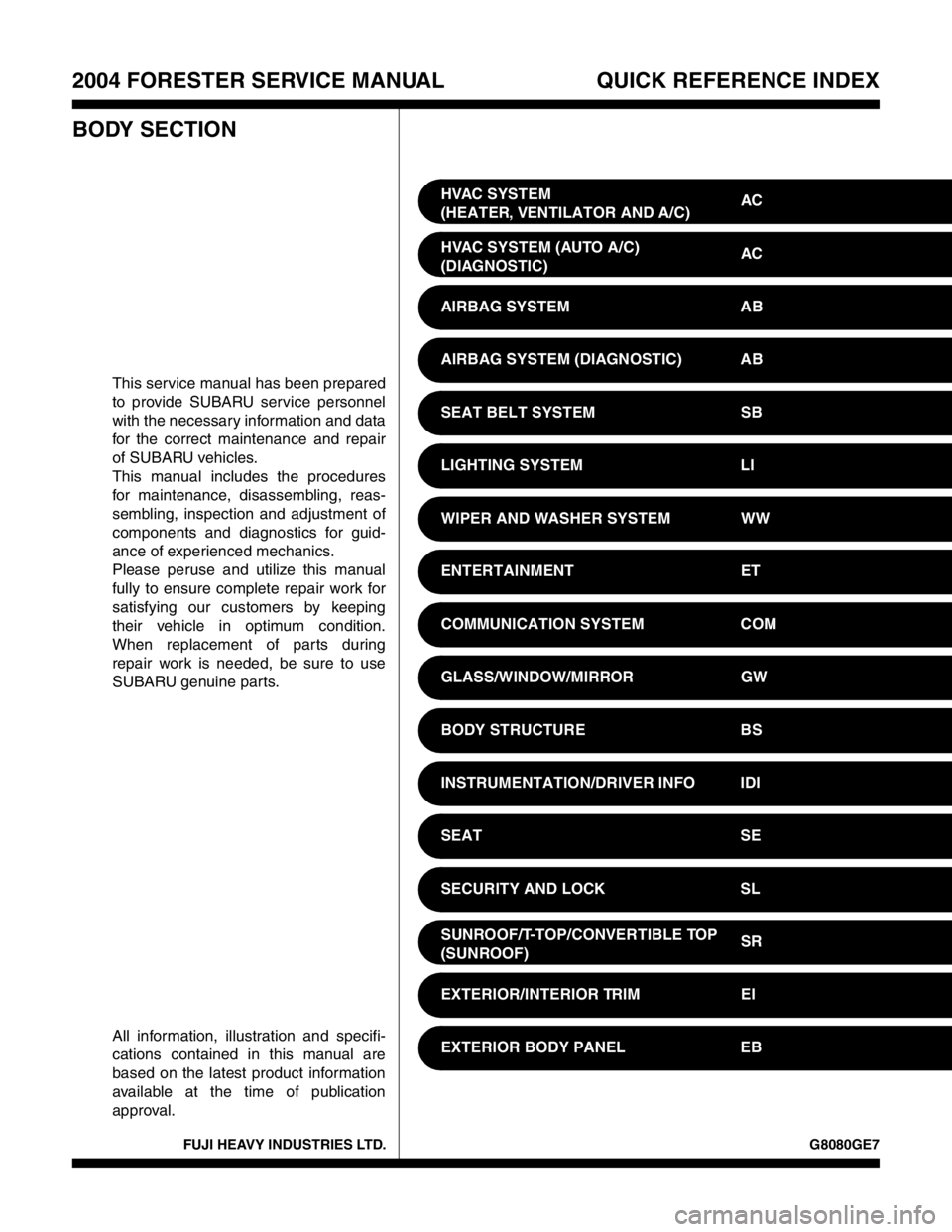
BODY SECTION
This service manual has been prepared
to provide SUBARU service personnel
with the necessary information and data
for the correct maintenance and repair
of SUBARU vehicles.
This manual includes the procedures
for maintenance, disassembling, reas-
sembling, inspection and adjustment of
components and diagnostics for guid-
ance of experienced mechanics.
Please peruse and utilize this manual
fully to ensure complete repair work for
satisfying our customers by keeping
their vehicle in optimum condition.
When replacement of parts during
repair work is needed, be sure to use
SUBARU genuine parts.
All information, illustration and specifi-
cations contained in this manual are
based on the latest product information
available at the time of publication
approval.HVAC SYSTEM
(HEATER, VENTILATOR AND A/C)AC
HVAC SYSTEM (AUTO A/C)
(DIAGNOSTIC)AC
AIRBAG SYSTEM AB
AIRBAG SYSTEM (DIAGNOSTIC) AB
SEAT BELT SYSTEM SB
LIGHTING SYSTEM LI
WIPER AND WASHER SYSTEM WW
ENTERTAINMENT ET
COMMUNICATION SYSTEM COM
GLASS/WINDOW/MIRROR GW
BODY STRUCTURE BS
INSTRUMENTATION/DRIVER INFO IDI
SEAT SE
SECURITY AND LOCK SL
SUNROOF/T-TOP/CONVERTIBLE TOP
(SUNROOF)SR
EXTERIOR/INTERIOR TRIM EI
EXTERIOR BODY PANEL EB
Page 416 of 2870

SE-12
SEAT
Front Seat
E: INSPECTION
Inspect that there is no tear and fray on backrest
cover assembly.
NOTE:
When there is tear or fray on the door side of back-
rest cover assembly, replace the backrest cover
assembly with a new one, because there is a pos-
sibility that the side airbag will not operate normally.
Page 419 of 2870
FUJI HEAVY INDUSTRIES LTD. G8080GE7
2004 FORESTER SERVICE MANUAL QUICK REFERENCE INDEX
BODY SECTION
This service manual has been prepared
to provide SUBARU service personnel
with the necessary information and data
for the correct maintenance and repair
of SUBARU vehicles.
This manual includes the procedures
for maintenance, disassembling, reas-
sembling, inspection and adjustment of
components and diagnostics for guid-
ance of experienced mechanics.
Please peruse and utilize this manual
fully to ensure complete repair work for
satisfying our customers by keeping
their vehicle in optimum condition.
When replacement of parts during
repair work is needed, be sure to use
SUBARU genuine parts.
All information, illustration and specifi-
cations contained in this manual are
based on the latest product information
available at the time of publication
approval.HVAC SYSTEM
(HEATER, VENTILATOR AND A/C)AC
HVAC SYSTEM (AUTO A/C)
(DIAGNOSTIC)AC
AIRBAG SYSTEM AB
AIRBAG SYSTEM (DIAGNOSTIC) AB
SEAT BELT SYSTEM SB
LIGHTING SYSTEM LI
WIPER AND WASHER SYSTEM WW
ENTERTAINMENT ET
COMMUNICATION SYSTEM COM
GLASS/WINDOW/MIRROR GW
BODY STRUCTURE BS
INSTRUMENTATION/DRIVER INFO IDI
SEAT SE
SECURITY AND LOCK SL
SUNROOF/T-TOP/CONVERTIBLE TOP
(SUNROOF)SR
EXTERIOR/INTERIOR TRIM EI
EXTERIOR BODY PANEL EB
Page 430 of 2870

SL-10
SECURITY AND LOCK
Door Lock Control System
2. CHECK FUSE
3. CHECK POWER SUPPLY AND GROUND CIRCUIT
Step Check Yes No
1 CHECK FUSE.
Remove and visually check the fuse No. 2 (in
the main fuse box).In the fuse blown out? Replace the fuse
with a new one.Check the power
supply and ground
circuit.
POWER SUPPLY
AND GROUND
CIRCUIT,
INSPECTION,
Door Lock Control
System.>
Step Check Yes No
1 CHECK POWER SUPPLY.
1) Disconnect the keyless entry control mod-
ule or double lock module harness connector.
2) Measure the voltage between the harness
connector terminal and chassis ground.
Connector & terminal
Without double lock:
(B176) No. 5, 16 (+) — Chassis ground (
−
):
With double lock:
(B324) No. 7, 8 (+) — Chassis ground (
−):Is the voltage more than 10 V? Go to step 2.Check the harness
for open circuits or
shorts between
the keyless entry
control module or
double lock mod-
ule and the fuse.
2 CHECK GROUND CIRCUIT.
Measure the resistance between the harness
connector terminal and chassis ground.
Connector & terminal
Without double lock:
(B176) No. 6, 14 — Chassis ground:
With double lock:
(B324) No. 9 — Chassis ground:Is the resistance less than 10
Ω?The power supply
and ground circuit
is OK.Repair the har-
ness.
Page 431 of 2870

SL-11
SECURITY AND LOCK
Door Lock Control System
4. CHECK DOOR LOCK SWITCH AND CIRCUIT
Step Check Yes No
1 CHECK DOOR LOCK SWITCH CIRCUIT.
1) Disconnect the keyless entry control mod-
ule or double lock module harness connector.
2) Measure the resistance between the har-
ness connector terminal and chassis ground
when moving the door lock switch to LOCK.
Connector & terminal
Without double lock:
(B176) No. 10 — Chassis ground:
With double lock:
(B325) No. 7 — Chassis ground:Is the resistance less than 10
Ω?Go to step 2.Go to step 3.
2 CHECK DOOR LOCK SWITCH CIRCUIT.
Measure the resistance between the harness
connector terminal and chassis ground when
the door lock switch is moved to UNLOCK.
Connector & terminal
Without double lock:
(B176) No. 8 — Chassis ground:
With double lock:
(B325) No. 4 — Chassis ground:Is the resistance less than 10
Ω?The door lock
switch is OK.Go to step 3.
3 CHECK DOOR LOCK SWITCH.
1) Disconnect the door lock switch harness
connector.
2) Measure the resistance between the door
lock switch terminals when moving the door
lock switch to LOCK.
Connector & terminal
LHD model:
(D7) No. 5 — No. 9
RHD model:
(D7) No. 15 — Switch ground:Is the resistance less than 1
Ω?Go to step 4.Replace the door
lock switch.
4 CHECK DOOR LOCK SWITCH.
Measure the resistance between the door lock
switch terminals when moving the door lock
switch to UNLOCK.
Connector & terminal
LHD model:
(D7) No. 5 — No. 8
RHD model:
(D7) No. 16 — Switch ground:Is the resistance less than 1
Ω?Check the harness
for open circuits or
shorts between
the keyless entry
control module or
double lock mod-
ule and the door
lock switch.Replace the door
lock switch.
Page 432 of 2870

SL-12
SECURITY AND LOCK
Door Lock Control System
5. CHECK DOOR LOCK ACTUATOR AND CIRCUIT
6. CHECK KEY CYLINDER LOCK SWITCH AND CIRCUIT
Step Check Yes No
1 CHECK OUTPUT SIGNAL.
Measure the voltage between the harness con-
nector terminal of keyless entry control module
or double lock module and chassis ground
when moving the door lock switch to LOCK.
Connector & terminal
Without double lock:
(B176) No. 18 (+) — Chassis ground (
−):
With double lock:
(B324) No. 3 (+) — Chassis ground (
−):Is the voltage more than 10 V? Go to step 2.Replace the key-
less entry control
module or double
lock module.
2 CHECK OUTPUT SIGNAL.
Measure the voltage between the harness con-
nector terminal of keyless entry control module
or double lock module and chassis ground
when moving the door lock switch to UNLOCK.
Connector & terminal
Without double lock:
(B176) No. 17 (+) — Chassis ground (
−):
With double lock:
(B324) No. 5 (+) — Chassis ground (
−):Is the voltage more than 10 V? Go to step 3.Replace the key-
less entry control
module or double
lock module.
3 CHECK DOOR LOCK ACTUATOR.
Check the door lock actuator.
Front door lock actuator:
Rear door lock actuator:
Rear gate latch lock actuator:
for open circuits or
shorts between
the keyless entry
control module or
double lock mod-
ule and the door
lock actuator.Replace the door
lock actuator.
Step Check Yes No
1 CHECK KEY CYLINDER LOCK SWITCH CIR-
CUIT.
1) Disconnect the double lock module har-
ness connector.
2) Measure the resistance between harness
connector terminal and chassis ground when
turning the key cylinder lock switch to lock
position.
Connector & terminal
(B325) No. 2 — Chassis ground:Is the resistance less than 10
Ω?Go to step 2.Go to step 3.
2 CHECK KEY CYLINDER LOCK SWITCH CIR-
CUIT.
Measure the resistance between harness con-
nector terminal and chassis ground when turn-
ing the key cylinder lock switch to unlock
position.
Connector & terminal
(B325) No. 3 — Chassis ground:Is the resistance less than 10
Ω?Key cylinder lock
switch is nor mal.Go to step 3.