engine repair SUBARU FORESTER 2004 Service User Guide
[x] Cancel search | Manufacturer: SUBARU, Model Year: 2004, Model line: FORESTER, Model: SUBARU FORESTER 2004Pages: 2870, PDF Size: 38.67 MB
Page 313 of 2870
ET-3
ENTERTAINMENT
Radio System
2. Radio System
A: WIRING DIAGRAM
1. RADIO
B: INSPECTION
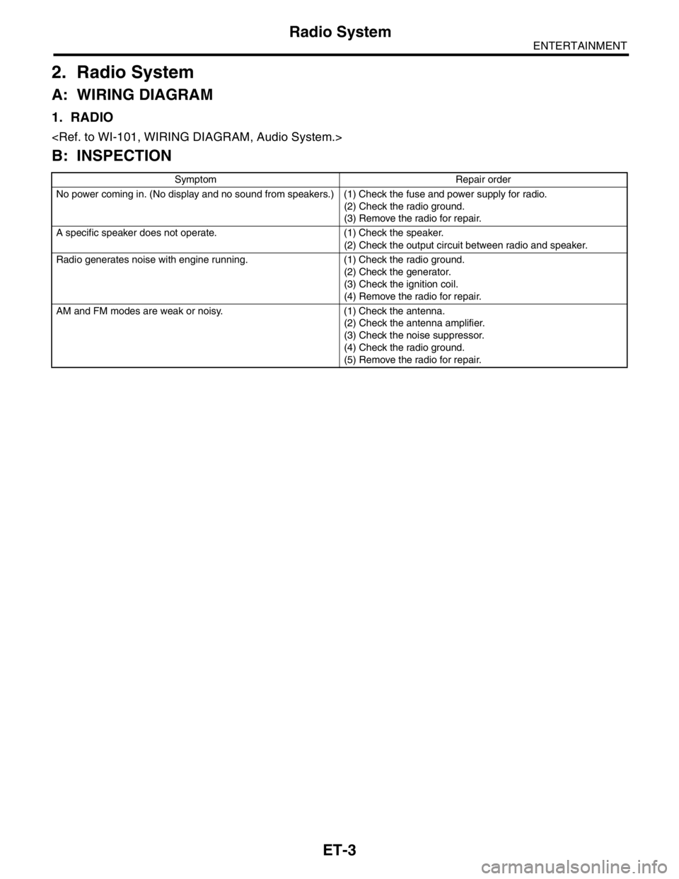
Symptom Repair order
No power coming in. (No display and no sound from speakers.) (1) Check the fuse and power supply for radio.
(2) Check the radio ground.
(3) Remove the radio for repair.
A specific speaker does not operate. (1) Check the speaker.
(2) Check the output circuit between radio and speaker.
Radio generates noise with engine running. (1) Check the radio ground.
(2) Check the generator.
(3) Check the ignition coil.
(4) Remove the radio for repair.
AM and FM modes are weak or noisy. (1) Check the antenna.
(2) Check the antenna amplifier.
(3) Check the noise suppressor.
(4) Check the radio ground.
(5) Remove the radio for repair.
Page 388 of 2870
IDI-4
INSTRUMENTATION/DRIVER INFO
Combination Meter System
B: INSPECTION
CAUTION:
When measuring voltage and resistance of the ECM, TCM, or each sensor, use a tapered pin with a
diameter of less than 0.64 mm (0.025 in) in order to avoid poor contact. Do not insert the pin more
than 2 mm (0.08 in).
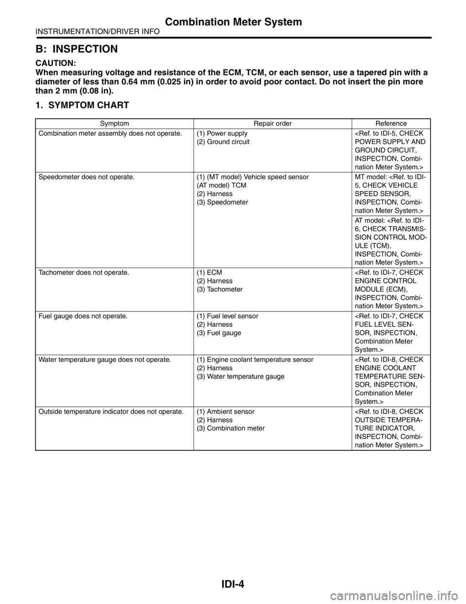
1. SYMPTOM CHART
Symptom Repair order Reference
Combination meter assembly does not operate. (1) Power supply
(2) Ground circuit
GROUND CIRCUIT,
INSPECTION, Combi-
nation Meter System.>
Speedometer does not operate. (1) (MT model) Vehicle speed sensor
(AT model) TCM
(2) Harness
(3) SpeedometerMT model:
SPEED SENSOR,
INSPECTION, Combi-
nation Meter System.>
AT model:
SION CONTROL MOD-
ULE (TCM),
INSPECTION, Combi-
nation Meter System.>
Tachometer does not operate. (1) ECM
(2) Harness
(3) Tachometer
MODULE (ECM),
INSPECTION, Combi-
nation Meter System.>
Fuel gauge does not operate. (1) Fuel level sensor
(2) Harness
(3) Fuel gauge
SOR, INSPECTION,
Combination Meter
System.>
Water temperature gauge does not operate. (1) Engine coolant temperature sensor
(2) Harness
(3) Water temperature gauge
TEMPERATURE SEN-
SOR, INSPECTION,
Combination Meter
System.>
Outside temperature indicator does not operate. (1) Ambient sensor
(2) Harness
(3) Combination meter
TURE INDICATOR,
INSPECTION, Combi-
nation Meter System.>
Page 389 of 2870
IDI-5
INSTRUMENTATION/DRIVER INFO
Combination Meter System
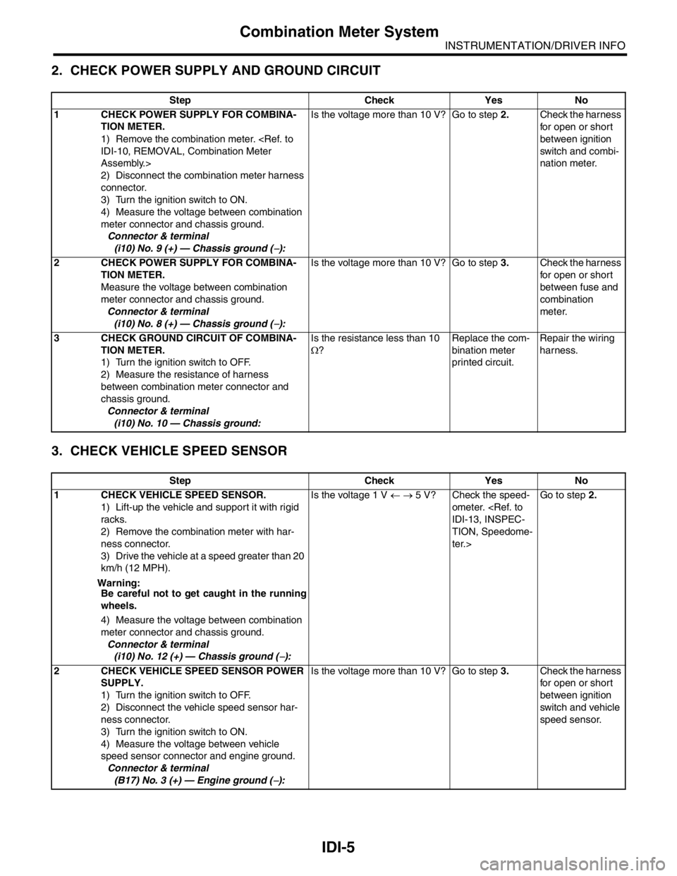
2. CHECK POWER SUPPLY AND GROUND CIRCUIT
3. CHECK VEHICLE SPEED SENSOR
Step Check Yes No
1 CHECK POWER SUPPLY FOR COMBINA-
TION METER.
1) Remove the combination meter.
Assembly.>
2) Disconnect the combination meter harness
connector.
3) Turn the ignition switch to ON.
4) Measure the voltage between combination
meter connector and chassis ground.
Connector & terminal
(i10) No. 9 (+) — Chassis ground (
−):Is the voltage more than 10 V? Go to step 2.Check the harness
for open or short
between ignition
switch and combi-
nation meter.
2 CHECK POWER SUPPLY FOR COMBINA-
TION METER.
Measure the voltage between combination
meter connector and chassis ground.
Connector & terminal
(i10) No. 8 (+) — Chassis ground (
−):Is the voltage more than 10 V? Go to step 3.Check the harness
for open or short
between fuse and
combination
meter.
3 CHECK GROUND CIRCUIT OF COMBINA-
TION METER.
1) Turn the ignition switch to OFF.
2) Measure the resistance of harness
between combination meter connector and
chassis ground.
Connector & terminal
(i10) No. 10 — Chassis ground:Is the resistance less than 10
Ω?Replace the com-
bination meter
printed circuit.Repair the wiring
harness.
Step Check Yes No
1 CHECK VEHICLE SPEED SENSOR.
1) Lift-up the vehicle and support it with rigid
racks.
2) Remove the combination meter with har-
ness connector.
3) Drive the vehicle at a speed greater than 20
km/h (12 MPH).
Warning:
Be careful not to get caught in the running
wheels.
4) Measure the voltage between combination
meter connector and chassis ground.
Connector & terminal
(i10) No. 12 (+) — Chassis ground (
−):Is the voltage 1 V ← → 5 V? Check the speed-
ometer.
TION, Speedome-
ter.>Go to step 2.
2 CHECK VEHICLE SPEED SENSOR POWER
SUPPLY.
1) Turn the ignition switch to OFF.
2) Disconnect the vehicle speed sensor har-
ness connector.
3) Turn the ignition switch to ON.
4) Measure the voltage between vehicle
speed sensor connector and engine ground.
Connector & terminal
(B17) No. 3 (+) — Engine ground (
−):Is the voltage more than 10 V? Go to step 3.Check the harness
for open or short
between ignition
switch and vehicle
speed sensor.
Page 390 of 2870
IDI-6
INSTRUMENTATION/DRIVER INFO
Combination Meter System
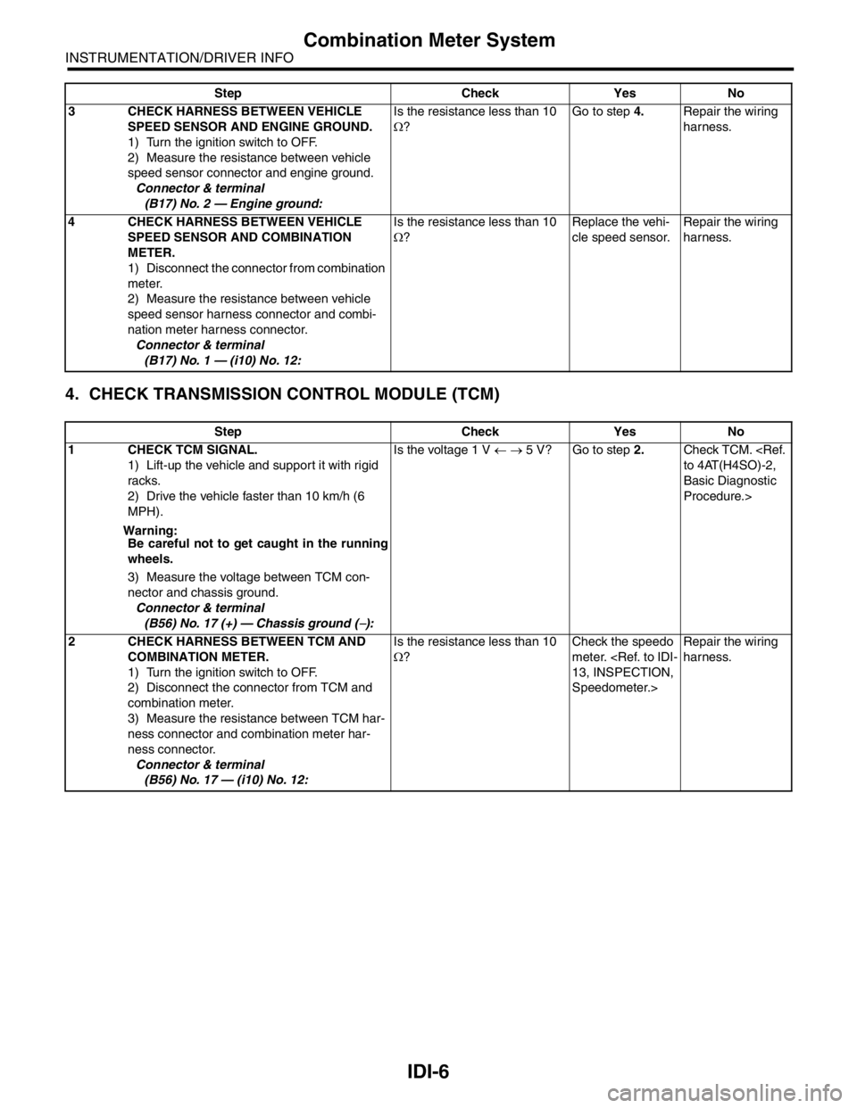
4. CHECK TRANSMISSION CONTROL MODULE (TCM)
3 CHECK HARNESS BETWEEN VEHICLE
SPEED SENSOR AND ENGINE GROUND.
1) Turn the ignition switch to OFF.
2) Measure the resistance between vehicle
speed sensor connector and engine ground.
Connector & terminal
(B17) No. 2 — Engine ground:Is the resistance less than 10
Ω?Go to step 4.Repair the wiring
harness.
4 CHECK HARNESS BETWEEN VEHICLE
SPEED SENSOR AND COMBINATION
METER.
1) Disconnect the connector from combination
meter.
2) Measure the resistance between vehicle
speed sensor harness connector and combi-
nation meter harness connector.
Connector & terminal
(B17) No. 1 — (i10) No. 12:Is the resistance less than 10
Ω?Replace the vehi-
cle speed sensor.Repair the wiring
harness.
Step Check Yes No
1 CHECK TCM SIGNAL.
1) Lift-up the vehicle and support it with rigid
racks.
2) Drive the vehicle faster than 10 km/h (6
MPH).
Warning:
Be careful not to get caught in the running
wheels.
3) Measure the voltage between TCM con-
nector and chassis ground.
Connector & terminal
(B56) No. 17 (+) — Chassis ground (
−):Is the voltage 1 V ← → 5 V? Go to step 2.Check TCM.
Basic Diagnostic
Procedure.>
2 CHECK HARNESS BETWEEN TCM AND
COMBINATION METER.
1) Turn the ignition switch to OFF.
2) Disconnect the connector from TCM and
combination meter.
3) Measure the resistance between TCM har-
ness connector and combination meter har-
ness connector.
Connector & terminal
(B56) No. 17 — (i10) No. 12:Is the resistance less than 10
Ω?Check the speedo
meter.
Speedometer.>Repair the wiring
harness. Step Check Yes No
Page 391 of 2870
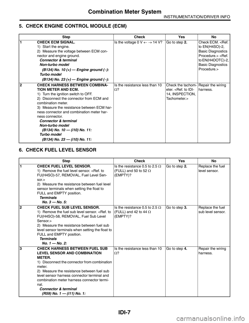
IDI-7
INSTRUMENTATION/DRIVER INFO
Combination Meter System
5. CHECK ENGINE CONTROL MODULE (ECM)
6. CHECK FUEL LEVEL SENSOR
Step Check Yes No
1 CHECK ECM SIGNAL.
1) Start the engine.
2) Measure the voltage between ECM con-
nector and engine ground.
Connector & terminal
Non-turbo model
(B134) No. 10 (+) — Engine ground (
−):
Turbo model
(B134) No. 23 (+) — Engine ground (
−):Is the voltage 0 V ← → 14 V? Go to step 2.Check ECM.
Basic Diagnostics
Procedure.>
Basic Diagnostics
Procedure.>
2 CHECK HARNESS BETWEEN COMBINA-
TION METER AND ECM.
1) Turn the ignition switch to OFF.
2) Disconnect the connector from ECM and
combination meter.
3) Measure the resistance between ECM har-
ness connector and combination meter har-
ness connector.
Connector & terminal
Non-turbo model
(B134) No. 10 — (i10) No. 11:
Turbo model
(B134) No. 23 — (i10) No. 11:Is the resistance less than 10
Ω?Check the tachom-
eter.
Tachometer.>Repair the wiring
harness.
Step Check Yes No
1 CHECK FUEL LEVEL SENSOR.
1) Remove the fuel level sensor.
sor.>
2) Measure the resistance between fuel level
sensor terminals when setting the float to
FULL and EMPTY position.
Te r m i n a l s
No. 3 — No. 5:Is the resistance 0.5 to 2.5 Ω
(FULL) and 50 to 52 Ω
(EMPTY)?Go to step 2.Replace the fuel
level sensor.
2 CHECK FUEL SUB LEVEL SENSOR.
1) Remove the fuel sub level sensor.
Sensor.>
2) Measure the resistance between fuel sub
level sensor terminals when setting the float to
FULL and EMPTY position.
Te r m i n a l s
No. 1 — No. 2:Is the resistance 0.5 to 2.5 Ω
(FULL) and 42 to 44 Ω
(EMPTY)?Go to step 3.Replace the fuel
sub level sensor.
3 CHECK HARNESS BETWEEN FUEL SUB
LEVEL SENSOR AND COMBINATION
METER.
1) Disconnect the connector from combination
meter.
2) Measure the resistance between fuel sub
level sensor harness connector terminal and
combination meter harness connector termi-
nal.
Connector & terminal
(R59) No. 1 — (i11) No. 1:Is the resistance less than 10
Ω?Go to step 4.Repair the wiring
harness.
Page 392 of 2870
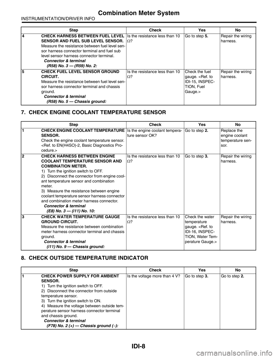
IDI-8
INSTRUMENTATION/DRIVER INFO
Combination Meter System
7. CHECK ENGINE COOLANT TEMPERATURE SENSOR
8. CHECK OUTSIDE TEMPERATURE INDICATOR
4 CHECK HARNESS BETWEEN FUEL LEVEL
SENSOR AND FUEL SUB LEVEL SENSOR.
Measure the resistance between fuel level sen-
sor harness connector terminal and fuel sub
level sensor harness connector terminal.
Connector & terminal
(R58) No. 3 — (R59) No. 2:Is the resistance less than 10
Ω?Go to step 5.Repair the wiring
harness.
5 CHECK FUEL LEVEL SENSOR GROUND
CIRCUIT.
Measure the resistance between fuel level sen-
sor harness connector terminal and chassis
ground.
Connector & terminal
(R58) No. 5 — Chassis ground:Is the resistance less than 10
Ω?Check the fuel
gauge.
TION, Fuel
Gauge.>Repair the wiring
harness.
Step Check Yes No
1 CHECK ENGINE COOLANT TEMPERATURE
SENSOR.
Check the engine coolant temperature sensor.
ture sensor OK?Go to step 2.Replace the
engine coolant
temperature sen-
sor.
2 CHECK HARNESS BETWEEN ENGINE
COOLANT TEMPERATURE SENSOR AND
COMBINATION METER.
1) Turn the ignition switch to OFF.
2) Disconnect the connector from engine cool-
ant temperature sensor and combination
meter.
3) Measure the resistance between engine
coolant temperature sensor harness connector
and combination meter harness connector.
Connector & terminal
(E8) No. 3 — (i11) No. 10:Is the resistance less than 10
Ω?Go to step 3.Repair the wiring
harness.
3 CHECK WATER TEMPERATURE GAUGE
GROUND CIRCUIT.
Measure the resistance between combination
meter harness connector terminal and chassis
ground.
Connector & terminal
(i11) No. 9 — Chassis ground:Is the resistance less than 10
Ω?Check the water
temperature
gauge.
TION, Water Tem-
perature Gauge.>Repair the wiring
harness.
Step Check Yes No
1 CHECK POWER SUPPLY FOR AMBIENT
SENSOR.
1) Turn the ignition switch to OFF.
2) Disconnect the connector from outside
temperature sensor.
3) Turn the ignition switch to ON.
4) Measure the voltage between outside tem-
perature sensor harness connector terminal
and chassis ground.
Connector & terminal
(F78) No. 2 (+) — Chassis ground (
−):Is the voltage more than 4 V? Go to step 3.Go to step 2. Step Check Yes No
Page 599 of 2870
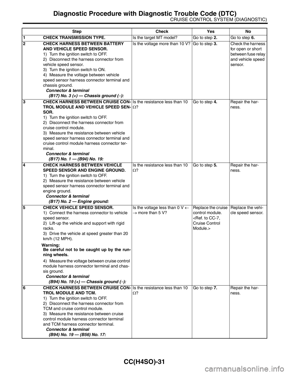
CC(H4SO)-31
CRUISE CONTROL SYSTEM (DIAGNOSTIC)
Diagnostic Procedure with Diagnostic Trouble Code (DTC)
Step Check Yes No
1 CHECK TRANSMISSION TYPE.Is the target MT model? Go to step 2.Go to step 6.
2 CHECK HARNESS BETWEEN BATTERY
AND VEHICLE SPEED SENSOR.
1) Turn the ignition switch to OFF.
2) Disconnect the harness connector from
vehicle speed sensor.
3) Turn the ignition switch to ON.
4) Measure the voltage between vehicle
speed sensor harness connector terminal and
chassis ground.
Connector & terminal
(B17) No. 3 (+) — Chassis ground (
−):Is the voltage more than 10 V? Go to step 3.Check the harness
for open or short
between fuse relay
and vehicle speed
sensor.
3 CHECK HARNESS BETWEEN CRUISE CON-
TROL MODULE AND VEHICLE SPEED SEN-
SOR.
1) Turn the ignition switch to OFF.
2) Disconnect the harness connector from
cruise control module.
3) Measure the resistance between vehicle
speed sensor harness connector terminal and
cruise control module harness connector ter-
minal.
Connector & terminal
(B17) No. 1 — (B94) No. 19:Is the resistance less than 10
Ω?Go to step 4.Repair the har-
ness.
4 CHECK HARNESS BETWEEN VEHICLE
SPEED SENSOR AND ENGINE GROUND.
1) Turn the ignition switch to OFF.
2) Measure the resistance between vehicle
speed sensor harness connector terminal and
engine ground.
Connector & terminal
(B17) No. 2 — Engine ground:Is the resistance less than 10
Ω?Go to step 5.Repair the har-
ness.
5 CHECK VEHICLE SPEED SENSOR.
1) Connect the harness connector to vehicle
speed sensor.
2) Lift-up the vehicle and support with rigid
racks.
3) Drive the vehicle at speed greater than 20
km/h (12 MPH).
Warning:
Be careful not to be caught up by the run-
ning wheels.
4) Measure the voltage between cruise control
module harness connector terminal and chas-
sis ground.
Connector & terminal
(B94) No. 19 (+) — Chassis ground (
−):Is the voltage less than 0 V ←
→ more than 5 V?Replace the cruise
control module.
Module.>Replace the vehi-
cle speed sensor.
6 CHECK HARNESS BETWEEN CRUISE CON-
TROL MODULE AND TCM.
1) Turn the ignition switch to OFF.
2) Disconnect the harness connector from
TCM and cruise control module.
3) Measure the resistance between cruise
control module harness connector terminal
and TCM harness connector terminal.
Connector & terminal
(B94) No. 19 — (B56) No. 17:Is the resistance less than 10
Ω?Go to step 7.Repair the har-
ness.
Page 639 of 2870
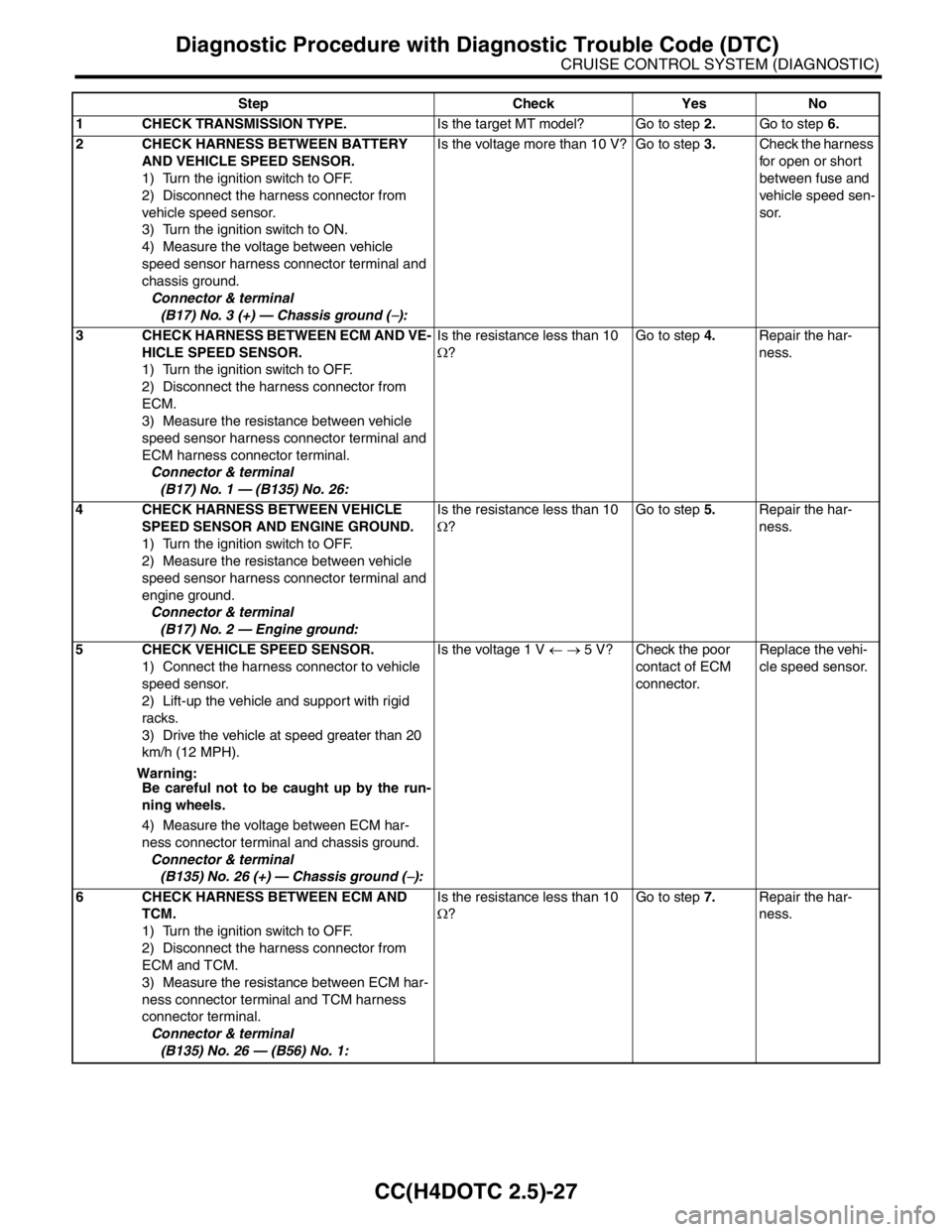
CC(H4DOTC 2.5)-27
CRUISE CONTROL SYSTEM (DIAGNOSTIC)
Diagnostic Procedure with Diagnostic Trouble Code (DTC)
Step Check Yes No
1 CHECK TRANSMISSION TYPE.Is the target MT model? Go to step 2.Go to step 6.
2 CHECK HARNESS BETWEEN BATTERY
AND VEHICLE SPEED SENSOR.
1) Turn the ignition switch to OFF.
2) Disconnect the harness connector from
vehicle speed sensor.
3) Turn the ignition switch to ON.
4) Measure the voltage between vehicle
speed sensor harness connector terminal and
chassis ground.
Connector & terminal
(B17) No. 3 (+) — Chassis ground (
−):Is the voltage more than 10 V? Go to step 3.Check the harness
for open or short
between fuse and
vehicle speed sen-
sor.
3 CHECK HARNESS BETWEEN ECM AND VE-
HICLE SPEED SENSOR.
1) Turn the ignition switch to OFF.
2) Disconnect the harness connector from
ECM.
3) Measure the resistance between vehicle
speed sensor harness connector terminal and
ECM harness connector terminal.
Connector & terminal
(B17) No. 1 — (B135) No. 26:Is the resistance less than 10
Ω?Go to step 4.Repair the har-
ness.
4 CHECK HARNESS BETWEEN VEHICLE
SPEED SENSOR AND ENGINE GROUND.
1) Turn the ignition switch to OFF.
2) Measure the resistance between vehicle
speed sensor harness connector terminal and
engine ground.
Connector & terminal
(B17) No. 2 — Engine ground:Is the resistance less than 10
Ω?Go to step 5.Repair the har-
ness.
5 CHECK VEHICLE SPEED SENSOR.
1) Connect the harness connector to vehicle
speed sensor.
2) Lift-up the vehicle and support with rigid
racks.
3) Drive the vehicle at speed greater than 20
km/h (12 MPH).
Warning:
Be careful not to be caught up by the run-
ning wheels.
4) Measure the voltage between ECM har-
ness connector terminal and chassis ground.
Connector & terminal
(B135) No. 26 (+) — Chassis ground (
−):Is the voltage 1 V ← → 5 V? Check the poor
contact of ECM
connector.Replace the vehi-
cle speed sensor.
6 CHECK HARNESS BETWEEN ECM AND
TCM.
1) Turn the ignition switch to OFF.
2) Disconnect the harness connector from
ECM and TCM.
3) Measure the resistance between ECM har-
ness connector terminal and TCM harness
connector terminal.
Connector & terminal
(B135) No. 26 — (B56) No. 1:Is the resistance less than 10
Ω?Go to step 7.Repair the har-
ness.
Page 644 of 2870
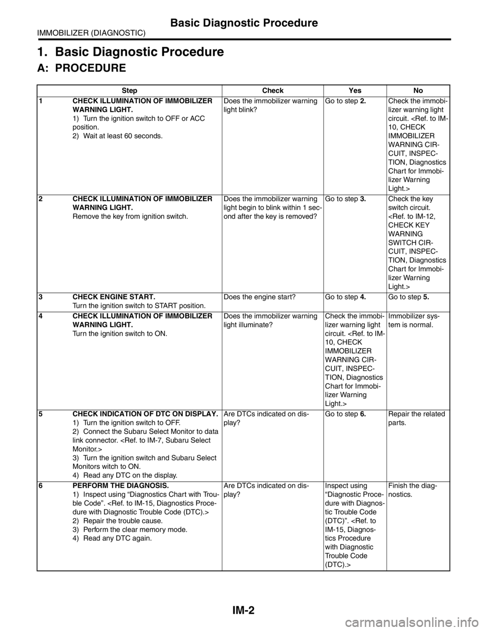
IM-2
IMMOBILIZER (DIAGNOSTIC)
Basic Diagnostic Procedure
1. Basic Diagnostic Procedure
A: PROCEDURE
Step Check Yes No
1 CHECK ILLUMINATION OF IMMOBILIZER
WARNING LIGHT.
1) Turn the ignition switch to OFF or ACC
position.
2) Wait at least 60 seconds.Does the immobilizer warning
light blink?Go to step 2.Check the immobi-
lizer warning light
circuit.
IMMOBILIZER
WARNING CIR-
CUIT, INSPEC-
TION, Diagnostics
Chart for Immobi-
lizer Warning
Light.>
2 CHECK ILLUMINATION OF IMMOBILIZER
WARNING LIGHT.
Remove the key from ignition switch.Does the immobilizer warning
light begin to blink within 1 sec-
ond after the key is removed?Go to step 3.Check the key
switch circuit.
WARNING
SWITCH CIR-
CUIT, INSPEC-
TION, Diagnostics
Chart for Immobi-
lizer Warning
Light.>
3 CHECK ENGINE START.
Turn the ignition switch to START position.Does the engine start? Go to step 4.Go to step 5.
4 CHECK ILLUMINATION OF IMMOBILIZER
WARNING LIGHT.
Turn the ignition switch to ON.Does the immobilizer warning
light illuminate?Check the immobi-
lizer warning light
circuit.
IMMOBILIZER
WARNING CIR-
CUIT, INSPEC-
TION, Diagnostics
Chart for Immobi-
lizer Warning
Light.>Immobilizer sys-
tem is normal.
5 CHECK INDICATION OF DTC ON DISPLAY.
1) Turn the ignition switch to OFF.
2) Connect the Subaru Select Monitor to data
link connector.
3) Turn the ignition switch and Subaru Select
Monitors witch to ON.
4) Read any DTC on the display. Are DTCs indicated on dis-
play?Go to step 6.Repair the related
parts.
6 PERFORM THE DIAGNOSIS.
1) Inspect using “Diagnostics Chart with Trou-
ble Code”.
2) Repair the trouble cause.
3) Perform the clear memory mode.
4) Read any DTC again.Are DTCs indicated on dis-
play?Inspect using
“Diagnostic Proce-
dure with Diagnos-
tic Trouble Code
(DTC)”.
tics Procedure
with Diagnostic
Trouble Code
(DTC).>Finish the diag-
nostics.
Page 649 of 2870
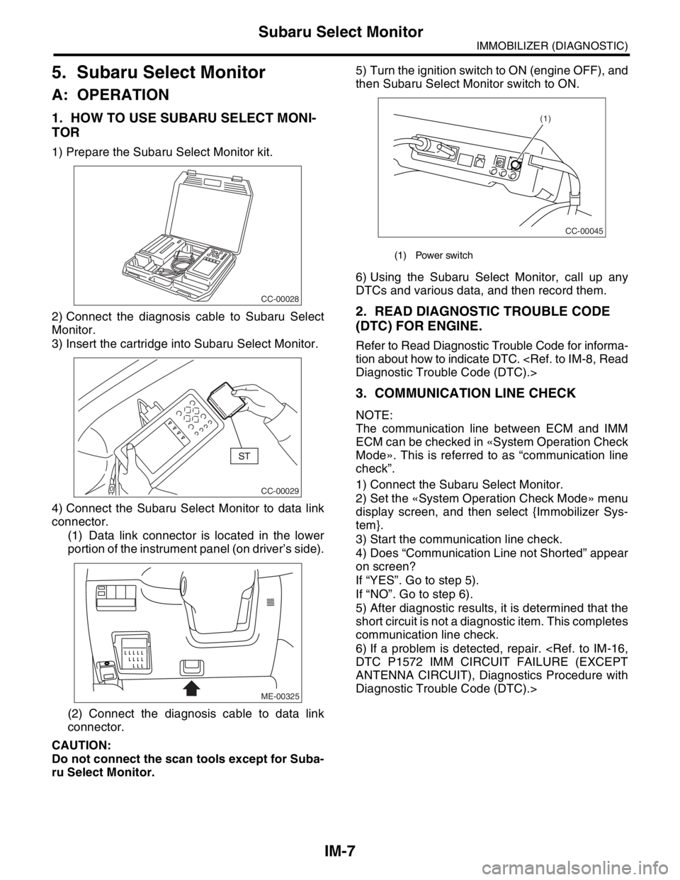
IM-7
IMMOBILIZER (DIAGNOSTIC)
Subaru Select Monitor
5. Subaru Select Monitor
A: OPERATION
1. HOW TO USE SUBARU SELECT MONI-
TOR
1) Prepare the Subaru Select Monitor kit.
2) Connect the diagnosis cable to Subaru Select
Monitor.
3) Insert the cartridge into Subaru Select Monitor.
4) Connect the Subaru Select Monitor to data link
connector.
(1) Data link connector is located in the lower
portion of the instrument panel (on driver’s side).
(2) Connect the diagnosis cable to data link
connector.
CAUTION:
Do not connect the scan tools except for Suba-
ru Select Monitor.5) Turn the ignition switch to ON (engine OFF), and
then Subaru Select Monitor switch to ON.
6) Using the Subaru Select Monitor, call up any
DTCs and various data, and then record them.
2. READ DIAGNOSTIC TROUBLE CODE
(DTC) FOR ENGINE.
Refer to Read Diagnostic Trouble Code for informa-
tion about how to indicate DTC.
3. COMMUNICATION LINE CHECK
NOTE:
The communication line between ECM and IMM
ECM can be checked in «System Operation Check
Mode». This is referred to as “communication line
check”.
1) Connect the Subaru Select Monitor.
2) Set the «System Operation Check Mode» menu
display screen, and then select {Immobilizer Sys-
tem}.
3) Start the communication line check.
4) Does “Communication Line not Shorted” appear
on screen?
If “YES”. Go to step 5).
If “NO”. Go to step 6).
5) After diagnostic results, it is determined that the
short circuit is not a diagnostic item. This completes
communication line check.
6) If a problem is detected, repair.
ANTENNA CIRCUIT), Diagnostics Procedure with
Diagnostic Trouble Code (DTC).>
CC-00028
CC-00029
ME-00325
(1) Power switch
CC-00045
(1)