relay box SUBARU FORESTER 2004 Service Owner's Manual
[x] Cancel search | Manufacturer: SUBARU, Model Year: 2004, Model line: FORESTER, Model: SUBARU FORESTER 2004Pages: 2870, PDF Size: 38.67 MB
Page 633 of 2870
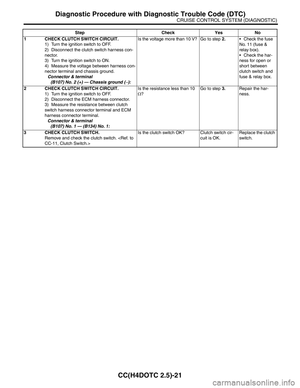
CC(H4DOTC 2.5)-21
CRUISE CONTROL SYSTEM (DIAGNOSTIC)
Diagnostic Procedure with Diagnostic Trouble Code (DTC)
Step Check Yes No
1 CHECK CLUTCH SWITCH CIRCUIT.
1) Turn the ignition switch to OFF.
2) Disconnect the clutch switch harness con-
nector.
3) Turn the ignition switch to ON.
4) Measure the voltage between harness con-
nector terminal and chassis ground.
Connector & terminal
(B107) No. 2 (+) — Chassis ground (
−):Is the voltage more than 10 V? Go to step 2. Check the fuse
No. 11 (fuse &
relay box).
Check the har-
ness for open or
short between
clutch switch and
fuse & relay box.
2 CHECK CLUTCH SWITCH CIRCUIT.
1) Turn the ignition switch to OFF.
2) Disconnect the ECM harness connector.
3) Measure the resistance between clutch
switch harness connector terminal and ECM
harness connector terminal.
Connector & terminal
(B107) No. 1 — (B134) No. 1:Is the resistance less than 10
Ω? Go to step 3.Repair the har-
ness.
3 CHECK CLUTCH SWITCH.
Remove and check the clutch switch.
cuit is OK.Replace the clutch
switch.
Page 637 of 2870
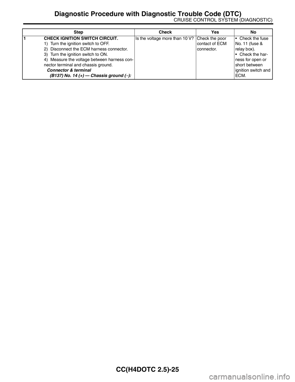
CC(H4DOTC 2.5)-25
CRUISE CONTROL SYSTEM (DIAGNOSTIC)
Diagnostic Procedure with Diagnostic Trouble Code (DTC)
Step Check Yes No
1 CHECK IGNITION SWITCH CIRCUIT.
1) Turn the ignition switch to OFF.
2) Disconnect the ECM harness connector.
3) Turn the ignition switch to ON.
4) Measure the voltage between harness con-
nector terminal and chassis ground.
Connector & terminal
(B137) No. 14 (+) — Chassis ground (
−): Is the voltage more than 10 V? Check the poor
contact of ECM
connector. Check the fuse
No. 11 (fuse &
relay box).
Check the har-
ness for open or
short between
ignition switch and
ECM.
Page 1300 of 2870

EN(H4SO)-202
ENGINE (DIAGNOSTIC)
Diagnostic Procedure with Diagnostic Trouble Code (DTC)
Step Check Yes No
1 CHECK OUTPUT SIGNAL FROM ECM.
1) Turn the ignition switch to OFF.
2) Connect the test mode connector at the
lower portion of instrument panel (on the
driver’s side).
3) Turn the ignition switch to ON.
4) While operating the radiator fan relay, mea-
sure the voltage between ECM and chassis
ground.
N
OTE:
Radiator fan relay operation can be executed
using Subaru Select Monitor. For procedure,
refer to “Compulsory Valve Operation Check
Mode”.
Connector & terminal
(B134) No. 14 (+) — Chassis ground (
−):Is the voltage 0 — 10 V? Repair the poor
contact in ECM
connector.Go to step 2.
2 CHECK GROUND SHORT CIRCUIT IN RADI-
ATOR MAIN FAN RELAY CONTROL CIR-
CUIT.
1) Turn the ignition switch to OFF.
2) Disconnect the connector from ECM.
3) Measure the resistance of harness
between ECM connector and chassis ground.
Connector & terminal
(B134) No. 14 — Chassis ground:Is the resistance less than 10
Ω?Repair the ground
short circuit in
radiator main fan
relay control cir-
cuit.Go to step 3.
3 CHECK POWER SUPPLY FOR RELAY.
1) Remove the main fan relay from A/C relay
holder.
2) Turn the ignition switch to ON.
3) Measure the voltage between fuse and
relay box (F/B) connector and chassis ground.
Connector & terminal
(F27) No. 34 (+) — Chassis ground (
−):Is the voltage more than 10 V? Go to step 4.Repair open circuit
in harness
between ignition
switch and fuse
and relay box (F/B)
connector.
4 CHECK MAIN FAN RELAY.
1) Turn the ignition switch to OFF.
2) Measure the resistance between main fan
relay terminals.
Te r m i n a l s
No. 32 — No. 34:Is the resistance 87 — 107 Ω? Go to step 5.Replace the main
fan relay.
5 CHECK OPEN CIRCUIT IN MAIN FAN RE-
LAY CONTROL CIRCUIT.
Measure the resistance of harness between
ECM and main fan relay connector.
Connector & terminal
(B134) No. 14 — (F27) No. 32:Is the resistance less than 1
Ω?Go to step 6.Repair harness
and connector.
NOTE:
In this case repair
the following:
Open circuit in
harness between
ECM and main fan
relay connector
Poor contact in
coupling connector
6 CHECK POOR CONTACT.
Check poor contact in ECM or main fan relay
connector. Is there poor contact in ECM or
main fan relay connector?Repair the poor
contact in ECM or
main fan relay con-
nector.Contact the SUB-
ARU dealer.
Page 1406 of 2870

FU(H4DOTC)-51
FUEL INJECTION (FUEL SYSTEM)
Main Relay
21.Main Relay
A: REMOVAL
1) Disconnect the ground cable from battery.
2) Remove the glove box.
3) Remove the bolt which holds the main relay
bracket on body.
4) Disconnect the connectors from main relay.
B: INSTALLATION
Install in the reverse order of removal.
FU-00009
FU-00317
Page 1407 of 2870

FU(H4DOTC)-52
FUEL INJECTION (FUEL SYSTEM)
Fuel Pump Relay
22.Fuel Pump Relay
A: REMOVAL
1) Disconnect the ground cable from battery.
2) Remove the glove box.
3) Remove the bolt which holds the fuel pump relay
bracket on body.
4) Disconnect the connector from fuel pump relay.
5) Remove the fuel pump relay from mounting
bracket.
B: INSTALLATION
Install in the reverse order of removal.
FU-00009
FU-00262
Page 1867 of 2870
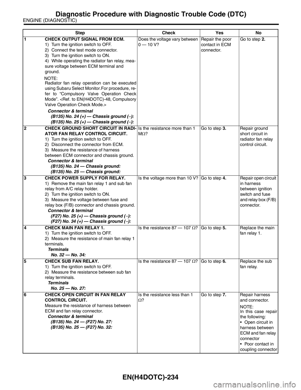
EN(H4DOTC)-234
ENGINE (DIAGNOSTIC)
Diagnostic Procedure with Diagnostic Trouble Code (DTC)
Step Check Yes No
1 CHECK OUTPUT SIGNAL FROM ECM.
1) Turn the ignition switch to OFF.
2) Connect the test mode connector.
3) Turn the ignition switch to ON.
4) While operating the radiator fan relay, mea-
sure voltage between ECM terminal and
ground.
N
OTE:
Radiator fan relay operation can be executed
using Subaru Select Monitor.For procedure, re-
fer to “Compulsory Valve Operation Check
Mode”.
Connector & terminal
(B135) No. 24 (+) — Chassis ground (
−):
(B135) No. 25 (+) — Chassis ground (
−):Does the voltage vary between
0 — 10 V?Repair the poor
contact in ECM
connector.Go to step 2.
2 CHECK GROUND SHORT CIRCUIT IN RADI-
ATOR FAN RELAY CONTROL CIRCUIT.
1) Turn the ignition switch to OFF.
2) Disconnect the connector from ECM.
3) Measure the resistance of harness
between ECM connector and chassis ground.
Connector & terminal
(B135) No. 24 — Chassis ground:
(B135) No. 25 — Chassis ground:Is the resistance more than 1
MΩ?Go to step 3.Repair ground
short circuit in
radiator fan relay
control circuit.
3 CHECK POWER SUPPLY FOR RELAY.
1) Remove the main fan relay 1 and sub fan
relay from A/C relay holder.
2) Turn the ignition switch to ON.
3) Measure the voltage between fuse and
relay box (F/B) connector and chassis ground.
Connector & terminal
(F27) No. 25 (+) — Chassis ground (
−):
(F27) No. 34 (+) — Chassis ground (
−):Is the voltage more than 10 V? Go to step 4.Repair open circuit
in harness
between ignition
switch and fuse
and relay box (F/B)
connector.
4 CHECK MAIN FAN RELAY 1.
1) Turn the ignition switch to OFF.
2) Measure the resistance of main fan relay 1
terminals.
Te r m i n a l s
No. 32 — No. 34:Is the resistance 87 — 107 Ω? Go to step 5.Replace the main
fan relay 1.
5 CHECK SUB FAN RELAY.
1) Turn the ignition switch to OFF.
2) Measure the resistance between sub fan
relay terminals.
Te r m i n a l s
No. 25 — No. 27:Is the resistance 87 — 107 Ω? Go to step 6.Replace the sub
fan relay.
6 CHECK OPEN CIRCUIT IN FAN RELAY
CONTROL CIRCUIT.
Measure the resistance of harness between
ECM and fan relay connector.
Connector & terminal
(B135) No. 24 — (F27) No. 27:
(B135) No. 25 — (F27) No. 32:Is the resistance less than 1
Ω?Go to step 7.Repair harness
and connector.
N
OTE:
In this case repair
the following:
Open circuit in
harness between
ECM and fan relay
connector
Poor contact in
coupling connector
Page 1972 of 2870

FU(H4DOTC 2.5)-42
FUEL INJECTION (FUEL SYSTEM)
Main Relay
18.Main Relay
A: REMOVAL
1) Disconnect the ground cable from battery.
2) Remove the glove box.
3) Remove the bolt which holds the main relay
bracket on the body.
4) Disconnect the connectors from the main relay.
B: INSTALLATION
Install in the reverse order of removal.
FU-00009
FU-00317
Page 1973 of 2870

FU(H4DOTC 2.5)-43
FUEL INJECTION (FUEL SYSTEM)
Fuel Pump Relay
19.Fuel Pump Relay
A: REMOVAL
1) Disconnect the ground cable from battery.
2) Remove the glove box.
3) Remove the bolt which holds fuel pump relay
bracket on the body.
4) Disconnect the connector from the fuel pump re-
lay.
5) Remove the fuel pump relay from the mounting
bracket.
B: INSTALLATION
Install in the reverse order of removal.
FU-00009
FU-00262
Page 2199 of 2870
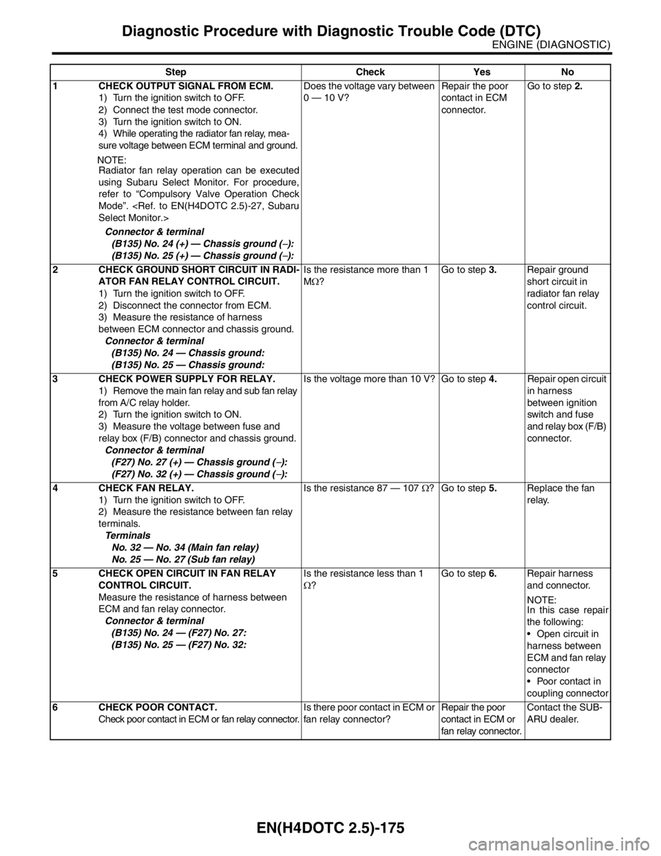
EN(H4DOTC 2.5)-175
ENGINE (DIAGNOSTIC)
Diagnostic Procedure with Diagnostic Trouble Code (DTC)
Step Check Yes No
1 CHECK OUTPUT SIGNAL FROM ECM.
1) Turn the ignition switch to OFF.
2) Connect the test mode connector.
3) Turn the ignition switch to ON.
4) While operating the radiator fan relay, mea-
sure voltage between ECM terminal and ground.
N
OTE:
Radiator fan relay operation can be executed
using Subaru Select Monitor. For procedure,
refer to “Compulsory Valve Operation Check
Mode”.
Connector & terminal
(B135) No. 24 (+) — Chassis ground (
−):
(B135) No. 25 (+) — Chassis ground (
−):Does the voltage vary between
0 — 10 V?Repair the poor
contact in ECM
connector.Go to step 2.
2 CHECK GROUND SHORT CIRCUIT IN RADI-
ATOR FAN RELAY CONTROL CIRCUIT.
1) Turn the ignition switch to OFF.
2) Disconnect the connector from ECM.
3) Measure the resistance of harness
between ECM connector and chassis ground.
Connector & terminal
(B135) No. 24 — Chassis ground:
(B135) No. 25 — Chassis ground:Is the resistance more than 1
MΩ?Go to step 3.Repair ground
short circuit in
radiator fan relay
control circuit.
3 CHECK POWER SUPPLY FOR RELAY.
1) Remove the main fan relay and sub fan relay
from A/C relay holder.
2) Turn the ignition switch to ON.
3) Measure the voltage between fuse and
relay box (F/B) connector and chassis ground.
Connector & terminal
(F27) No. 27 (+) — Chassis ground (
−):
(F27) No. 32 (+) — Chassis ground (
−):Is the voltage more than 10 V? Go to step 4.Repair open circuit
in harness
between ignition
switch and fuse
and relay box (F/B)
connector.
4 CHECK FAN RELAY.
1) Turn the ignition switch to OFF.
2) Measure the resistance between fan relay
terminals.
Te r m i n a l s
No. 32 — No. 34 (Main fan relay)
No. 25 — No. 27 (Sub fan relay)Is the resistance 87 — 107 Ω? Go to step 5.Replace the fan
relay.
5 CHECK OPEN CIRCUIT IN FAN RELAY
CONTROL CIRCUIT.
Measure the resistance of harness between
ECM and fan relay connector.
Connector & terminal
(B135) No. 24 — (F27) No. 27:
(B135) No. 25 — (F27) No. 32:Is the resistance less than 1
Ω?Go to step 6.Repair harness
and connector.
NOTE:
In this case repair
the following:
Open circuit in
harness between
ECM and fan relay
connector
Poor contact in
coupling connector
6 CHECK POOR CONTACT.
Check poor contact in ECM or fan relay connector.Is there poor contact in ECM or
fan relay connector?Repair the poor
contact in ECM or
fan relay connector.Contact the SUB-
ARU dealer.