oil pressure SUBARU FORESTER 2004 Service Manual PDF
[x] Cancel search | Manufacturer: SUBARU, Model Year: 2004, Model line: FORESTER, Model: SUBARU FORESTER 2004Pages: 2870, PDF Size: 38.67 MB
Page 1582 of 2870
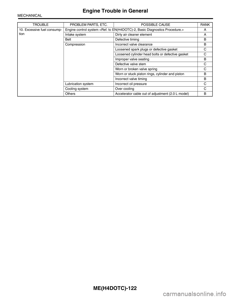
ME(H4DOTC)-122
MECHANICAL
Engine Trouble in General
10. Excessive fuel consump-
tionEngine control system
Intake system Dirty air cleaner element A
Belt Defective timing B
Compression Incorrect valve clearance B
Loosened spark plugs or defective gasket C
Loosened cylinder head bolts or defective gasket C
Improper valve seating B
Defective valve stem C
Worn or broken valve spring C
Worn or stuck piston rings, cylinder and piston B
Incorrect valve timing B
Lubrication system Incorrect oil pressure C
Cooling system Over cooling C
Others Accelerator cable out of adjustment (2.0 L model) B TROUBLE PROBLEM PARTS, ETC. POSSIBLE CAUSE RANK
Page 1583 of 2870
ME(H4DOTC)-123
MECHANICAL
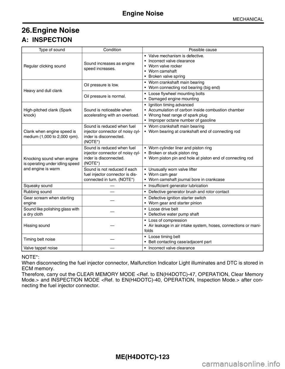
Engine Noise
26.Engine Noise
A: INSPECTION
NOTE*:
When disconnecting the fuel injector connector, Malfunction Indicator Light illuminates and DTC is stored in
ECM memory.
Therefore, carry out the CLEAR MEMORY MODE
necting the fuel injector connector.
Type of sound Condition Possible cause
Regular clicking soundSound increases as engine
speed increases. Valve mechanism is defective.
Incorrect valve clearance
Worn valve rocker
Worn camshaft
Broken valve spring
Heavy and dull clankOil pressure is low. Worn crankshaft main bearing
Worn connecting rod bearing (big end)
Oil pressure is normal. Loose flywheel mounting bolts
Damaged engine mounting
High-pitched clank (Spark
knock)Sound is noticeable when
accelerating with an overload. Ignition timing advanced
Accumulation of carbon inside combustion chamber
Wrong heat range of spark plug
Improper octane number of gasoline
Clank when engine speed is
medium (1,000 to 2,000 rpm).Sound is reduced when fuel
injector connector of noisy cyl-
inder is disconnected.
(NOTE*) Worn crankshaft main bearing
Worn bearing at crankshaft end of connecting rod
Knocking sound when engine
is operating under idling speed
and engine is warmSound is reduced when fuel
injector connector of noisy cyl-
inder is disconnected.
(NOTE*) Worn cylinder liner and piston ring
Broken or stuck piston ring
Worn piston pin and hole at piston end of connecting rod
Sound is not reduced if each
fuel injector connector is dis-
connected in turn. (NOTE*) Unusually worn valve lifter
Worn cam gear
Worn camshaft journal bore in crankcase
Squeaky sound — Insufficient generator lubrication
Rubbing sound — Defective generator brush and rotor contact
Gear scream when starting
engine— Defective ignition starter switch
Worn gear and starter pinion
Sound like polishing glass with
a dry cloth— Loose drive belt
Defective water pump shaft
Hissing sound — Loss of compression
Air leakage in air intake system, hoses, connections or mani-
folds
Timing belt noise — Loose timing belt
Belt contacting case/adjacent part
Valve tappet noise — Incorrect valve clearance
Page 1633 of 2870
EN(H4DOTC)-3
ENGINE (DIAGNOSTIC)
Basic Diagnostics Procedure
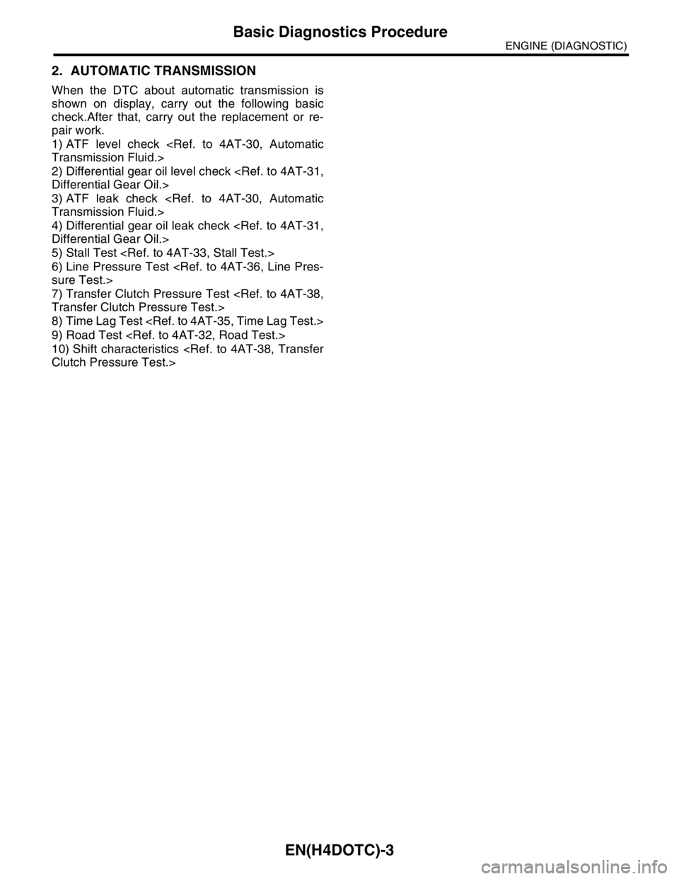
2. AUTOMATIC TRANSMISSION
When the DTC about automatic transmission is
shown on display, carry out the following basic
check.After that, carry out the replacement or re-
pair work.
1) ATF level check
2) Differential gear oil level check
3) ATF leak check
4) Differential gear oil leak check
5) Stall Test
6) Line Pressure Test
7) Transfer Clutch Pressure Test
8) Time Lag Test
9) Road Test
10) Shift characteristics
Page 1635 of 2870
EN(H4DOTC)-5
ENGINE (DIAGNOSTIC)
Check List for Interview
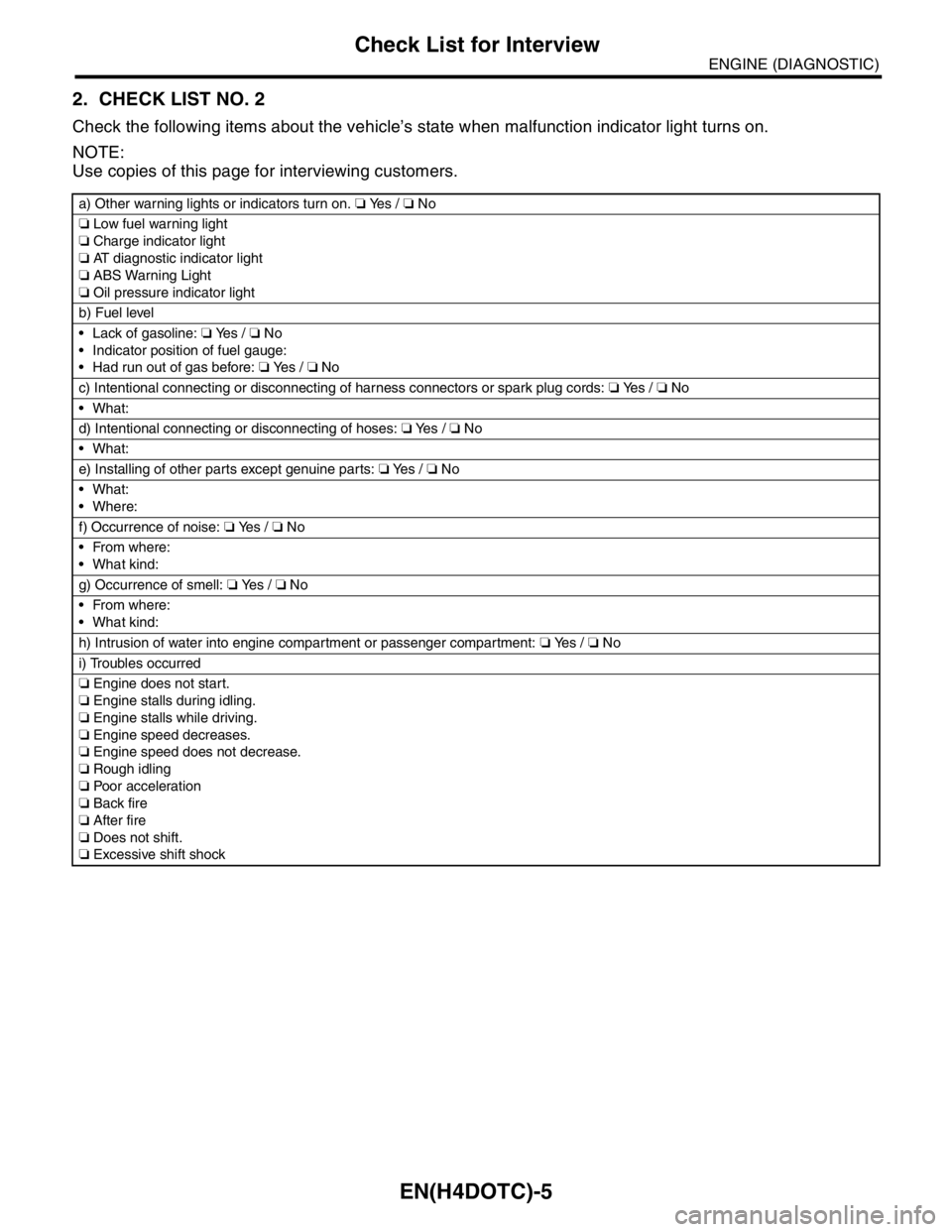
2. CHECK LIST NO. 2
Check the following items about the vehicle’s state when malfunction indicator light turns on.
NOTE:
Use copies of this page for interviewing customers.
a) Other warning lights or indicators turn on. ❏ Yes / ❏ No
❏ Low fuel warning light
❏ Charge indicator light
❏ AT diagnostic indicator light
❏ ABS Warning Light
❏ Oil pressure indicator light
b) Fuel level
Lack of gasoline: ❏ Yes / ❏ No
Indicator position of fuel gauge:
Had run out of gas before: ❏ Ye s / ❏ No
c) Intentional connecting or disconnecting of harness connectors or spark plug cords: ❏ Yes / ❏ No
What:
d) Intentional connecting or disconnecting of hoses: ❏ Ye s / ❏ No
What:
e) Installing of other parts except genuine parts: ❏ Ye s / ❏ No
What:
Where:
f) Occurrence of noise: ❏ Yes / ❏ No
From where:
What kind:
g) Occurrence of smell: ❏ Yes / ❏ No
From where:
What kind:
h) Intrusion of water into engine compartment or passenger compartment: ❏ Yes / ❏ No
i) Troubles occurred
❏ Engine does not start.
❏ Engine stalls during idling.
❏ Engine stalls while driving.
❏ Engine speed decreases.
❏ Engine speed does not decrease.
❏ Rough idling
❏ Poor acceleration
❏ Back fire
❏ After fire
❏ Does not shift.
❏ Excessive shift shock
Page 1655 of 2870
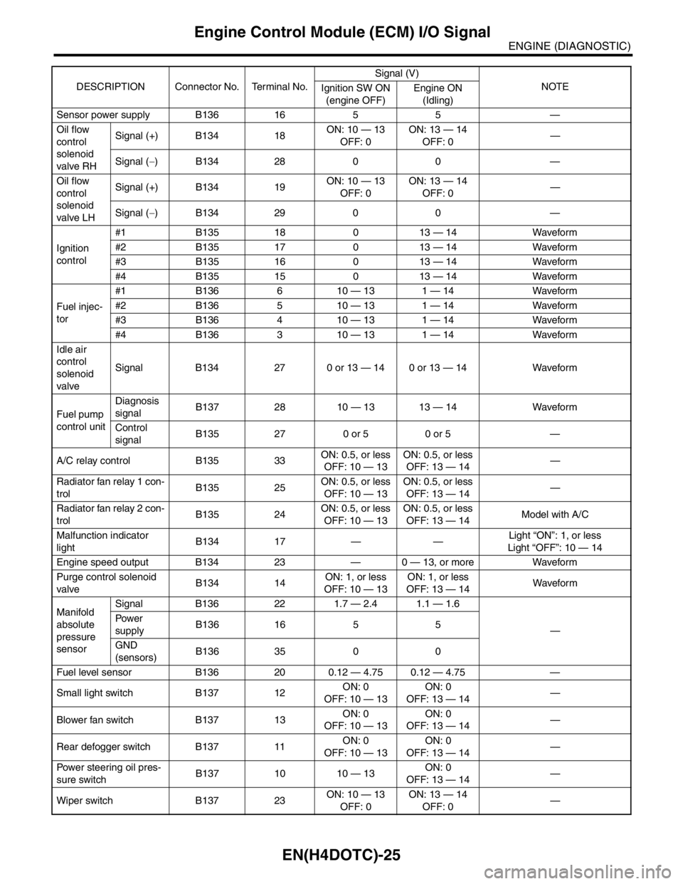
EN(H4DOTC)-25
ENGINE (DIAGNOSTIC)
Engine Control Module (ECM) I/O Signal
Sensor power supply B136 16 5 5 —
Oil flow
control
solenoid
valve RHSignal (+) B134 18ON: 10 — 13
OFF: 0ON: 13 — 14
OFF: 0—
Signal (−) B134 28 0 0 —
Oil flow
control
solenoid
valve LHSignal (+) B134 19ON: 10 — 13
OFF: 0ON: 13 — 14
OFF: 0—
Signal (−) B134 29 0 0 —
Ignition
control#1 B135 18 0 13 — 14 Waveform
#2 B135 17 0 13 — 14 Waveform
#3 B135 16 0 13 — 14 Waveform
#4 B135 15 0 13 — 14 Waveform
Fuel injec-
tor#1 B136 6 10 — 13 1 — 14 Waveform
#2 B136 5 10 — 13 1 — 14 Waveform
#3 B136 4 10 — 13 1 — 14 Waveform
#4 B136 3 10 — 13 1 — 14 Waveform
Idle air
control
solenoid
valveSignal B134 27 0 or 13 — 14 0 or 13 — 14 Waveform
Fuel pump
control unitDiagnosis
signalB137 28 10 — 13 13 — 14 Waveform
Control
signalB135 27 0 or 5 0 or 5 —
A/C relay control B135 33ON: 0.5, or less
OFF: 10 — 13ON: 0.5, or less
OFF: 13 — 14—
Radiator fan relay 1 con-
trolB135 25ON: 0.5, or less
OFF: 10 — 13ON: 0.5, or less
OFF: 13 — 14—
Radiator fan relay 2 con-
trolB135 24ON: 0.5, or less
OFF: 10 — 13ON: 0.5, or less
OFF: 13 — 14Model with A/C
Malfunction indicator
lightB134 17 — —Light “ON”: 1, or less
Light “OFF”: 10 — 14
Engine speed output B134 23 — 0 — 13, or more Waveform
Purge control solenoid
valveB134 14ON: 1, or less
OFF: 10 — 13ON: 1, or less
OFF: 13 — 14Wavefor m
Manifold
absolute
pressure
sensorSignal B136 22 1.7 — 2.4 1.1 — 1.6
— Pow er
supplyB136 16 5 5
GND
(sensors)B136 35 0 0
Fuel level sensor B136 20 0.12 — 4.75 0.12 — 4.75 —
Small light switch B137 12ON: 0
OFF: 10 — 13ON: 0
OFF: 13 — 14—
Blower fan switch B137 13ON: 0
OFF: 10 — 13ON: 0
OFF: 13 — 14—
Rear defogger switch B137 11ON: 0
OFF: 10 — 13ON: 0
OFF: 13 — 14—
Power steering oil pres-
sure switchB137 10 10 — 13ON: 0
OFF: 13 — 14—
Wiper switch B137 23ON: 10 — 13
OFF: 0ON: 13 — 14
OFF: 0— DESCRIPTION Connector No. Terminal No.Signal (V)
NOTE
Ignition SW ON
(engine OFF)Engine ON
(Idling)
Page 1664 of 2870

EN(H4DOTC)-34
ENGINE (DIAGNOSTIC)
Subaru Select Monitor
4. READ CURRENT DATA FOR ENGINE. (NORMAL MODE)
1) On the «Main Menu» display screen, select the {Each System Check} and press the [YES] key.
2) On the «System Selection Menu» display screen, select the {Engine} and press the [YES] key.
3) Press the [YES] key after the information of engine type was displayed.
4) On the «Engine Diagnosis» screen, select the {Current Data Display/Save}, and then press the [YES] key.
5) On the «Data Display Menu» screen, select the {Data Display} and press the [YES] key.
6) Using the scroll key, move the display screen up or down until the desired data is shown.
A list of the support data is shown in the following table.
Remarks Display Unit of measure
Battery voltage Battery Voltage V
Vehicle speed signal Vehicle Speed km/h or MPH
Engine speed signal Engine Speed rpm
Engine coolant temperature signal Coolant Temp.°C or °F
Ignition timing signal Ignition Timing deg
Throttle position signal Throttle Opening Angle %
Throttle position signal Throttle Sensor Voltage V
Injection pulse width Fuel Injection #1 Pulse ms
Idle air control signal ISC Valve Duty Ratio %
generated duty control signal ALT Duty %
Fuel pump duty control signal Fuel Pump Duty %
A/F sensor current A/F Sensor #1 Current mA
A/F sensor resistance A/F Sensor #1 ResistanceΩ
Front oxygen (A/F) sensor output signal A/F Sensor #1 —
Rear oxygen sensor output signalRear O
2 Sensor
V
Short term fuel trim A/F Correction #1 %
Knock sensor correction Knocking Correction deg
Atmospheric pressure signal Atmosphere Pressure mmHg, kPa, inHg or psi
Intake manifold relative pressure signal Mani. Relative Pressure mmHg, kPa, inHg or psi
Intake manifold absolute pressure signal Mani. Absolute Pressure mmHg, kPa, inHg or psi
A/F correction (short term fuel trim) by rear oxygen sensor A/F Correction #3 %
Long term whole fuel trim A/F Learning #1 %
Canister purge control solenoid valve duty ratio CPC Valve Duty Ratio %
Primary supercharged pressure control signal Primary Control %
Tumble generated valve position sensor signal (RH side) TGV Position Sensor R V
Tumble generated valve position sensor signal (LH side) TGV Position Sensor L V
Tumble generated valve drive signal TGV Drive OPEN or CLOSE
Fuel level signal Fuel Level Voltage V
Intake air temperature signal Intake Air Temp.°C or °F
Mass air flow sensor signal Mass Air Flow g/s
Mass air flow sensor signal Air Flow Sensor Voltage V
Valve Timing Signal VVT Adv. Ang. amount R deg
Valve Timing Signal VVT Adv. Ang. amount L deg
Oil flow control solenoid valve signal OCV Duty R %
Oil flow control solenoid valve signal OCV Duty L %
Oil flow control solenoid valve current OCV current R mA
Oil flow control solenoid valve current OCV Current L mA
AT/MT identification signal AT Vehicle ID Signal AT or MT
Test Mode Signal Test Mode Signal ON or OFF
Load switch signal Electric Load Signal ON or OFF
Ignition switch signal Ignition Switch ON or OFF
Neutral position switch signal Neutral Position Switch ON or OFF
Air conditioning switch signal A/C Switch ON or OFF
Page 1697 of 2870
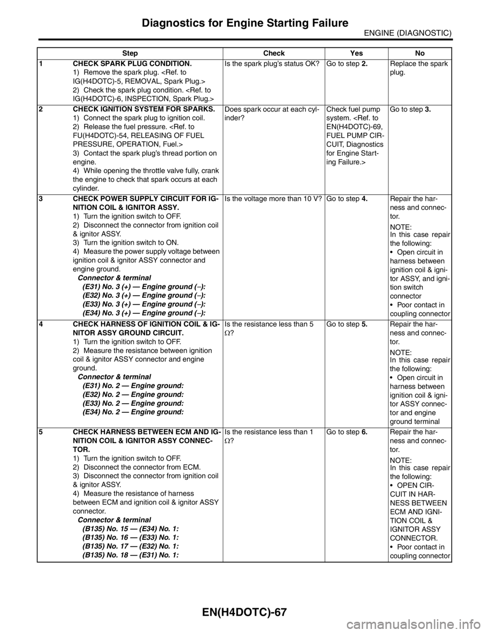
EN(H4DOTC)-67
ENGINE (DIAGNOSTIC)
Diagnostics for Engine Starting Failure
Step Check Yes No
1 CHECK SPARK PLUG CONDITION.
1) Remove the spark plug.
2) Check the spark plug condition.
plug.
2 CHECK IGNITION SYSTEM FOR SPARKS.
1) Connect the spark plug to ignition coil.
2) Release the fuel pressure.
PRESSURE, OPERATION, Fuel.>
3) Contact the spark plug’s thread portion on
engine.
4) While opening the throttle valve fully, crank
the engine to check that spark occurs at each
cylinder.Does spark occur at each cyl-
inder?Check fuel pump
system.
FUEL PUMP CIR-
CUIT, Diagnostics
for Engine Start-
ing Failure.>Go to step 3.
3 CHECK POWER SUPPLY CIRCUIT FOR IG-
NITION COIL & IGNITOR ASSY.
1) Turn the ignition switch to OFF.
2) Disconnect the connector from ignition coil
& ignitor ASSY.
3) Turn the ignition switch to ON.
4) Measure the power supply voltage between
ignition coil & ignitor ASSY connector and
engine ground.
Connector & terminal
(E31) No. 3 (+) — Engine ground (
−):
(E32) No. 3 (+) — Engine ground (
−):
(E33) No. 3 (+) — Engine ground (
−):
(E34) No. 3 (+) — Engine ground (
−):Is the voltage more than 10 V? Go to step 4.Repair the har-
ness and connec-
tor.
N
OTE:
In this case repair
the following:
Open circuit in
harness between
ignition coil & igni-
tor ASSY, and igni-
tion switch
connector
Poor contact in
coupling connector
4 CHECK HARNESS OF IGNITION COIL & IG-
NITOR ASSY GROUND CIRCUIT.
1) Turn the ignition switch to OFF.
2) Measure the resistance between ignition
coil & ignitor ASSY connector and engine
ground.
Connector & terminal
(E31) No. 2 — Engine ground:
(E32) No. 2 — Engine ground:
(E33) No. 2 — Engine ground:
(E34) No. 2 — Engine ground:Is the resistance less than 5
Ω?Go to step 5.Repair the har-
ness and connec-
tor.
NOTE:
In this case repair
the following:
Open circuit in
harness between
ignition coil & igni-
tor ASSY connec-
tor and engine
ground terminal
5 CHECK HARNESS BETWEEN ECM AND IG-
NITION COIL & IGNITOR ASSY CONNEC-
TOR.
1) Turn the ignition switch to OFF.
2) Disconnect the connector from ECM.
3) Disconnect the connector from ignition coil
& ignitor ASSY.
4) Measure the resistance of harness
between ECM and ignition coil & ignitor ASSY
connector.
Connector & terminal
(B135) No. 15 — (E34) No. 1:
(B135) No. 16 — (E33) No. 1:
(B135) No. 17 — (E32) No. 1:
(B135) No. 18 — (E31) No. 1:Is the resistance less than 1
Ω?Go to step 6.Repair the har-
ness and connec-
tor.
N
OTE:
In this case repair
the following:
OPEN CIR-
CUIT IN HAR-
NESS BETWEEN
ECM AND IGNI-
TION COIL &
IGNITOR ASSY
CONNECTOR.
Poor contact in
coupling connector
Page 1818 of 2870
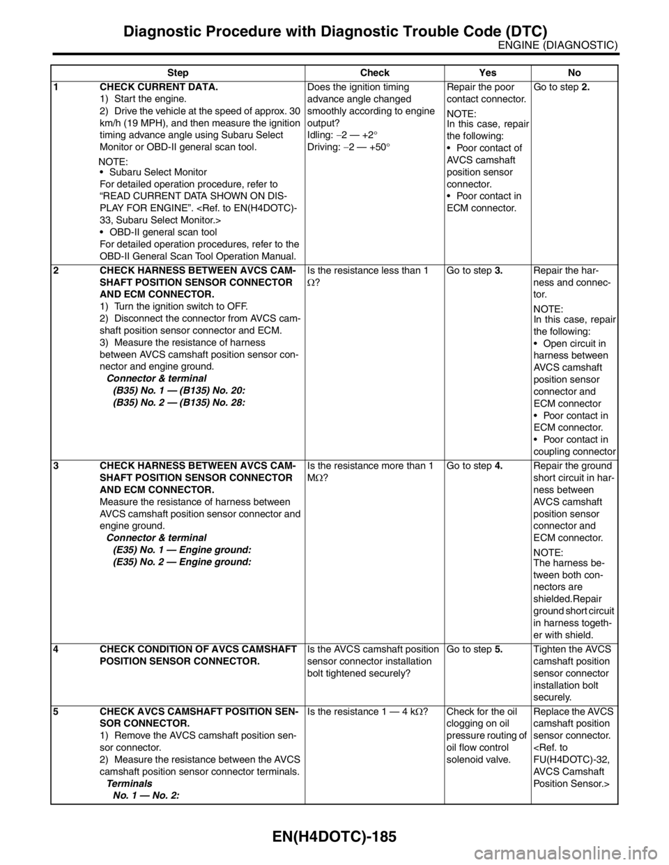
EN(H4DOTC)-185
ENGINE (DIAGNOSTIC)
Diagnostic Procedure with Diagnostic Trouble Code (DTC)
Step Check Yes No
1 CHECK CURRENT DATA.
1) Start the engine.
2) Drive the vehicle at the speed of approx. 30
km/h (19 MPH), and then measure the ignition
timing advance angle using Subaru Select
Monitor or OBD-II general scan tool.
N
OTE:
Subaru Select Monitor
For detailed operation procedure, refer to
“READ CURRENT DATA SHOWN ON DIS-
PLAY FOR ENGINE”.
OBD-II general scan tool
For detailed operation procedures, refer to the
OBD-II General Scan Tool Operation Manual.Does the ignition timing
advance angle changed
smoothly according to engine
output?
Idling: −2 — +2°
Driving: −2 — +50°Repair the poor
contact connector.
N
OTE:
In this case, repair
the following:
Poor contact of
AVCS camshaft
position sensor
connector.
Poor contact in
ECM connector.Go to step 2.
2 CHECK HARNESS BETWEEN AVCS CAM-
SHAFT POSITION SENSOR CONNECTOR
AND ECM CONNECTOR.
1) Turn the ignition switch to OFF.
2) Disconnect the connector from AVCS cam-
shaft position sensor connector and ECM.
3) Measure the resistance of harness
between AVCS camshaft position sensor con-
nector and engine ground.
Connector & terminal
(B35) No. 1 — (B135) No. 20:
(B35) No. 2 — (B135) No. 28:Is the resistance less than 1
Ω?Go to step 3.Repair the har-
ness and connec-
tor.
N
OTE:
In this case, repair
the following:
Open circuit in
harness between
AVCS camshaft
position sensor
connector and
ECM connector
Poor contact in
ECM connector.
Poor contact in
coupling connector
3 CHECK HARNESS BETWEEN AVCS CAM-
SHAFT POSITION SENSOR CONNECTOR
AND ECM CONNECTOR.
Measure the resistance of harness between
AVCS camshaft position sensor connector and
engine ground.
Connector & terminal
(E35) No. 1 — Engine ground:
(E35) No. 2 — Engine ground:Is the resistance more than 1
MΩ?Go to step 4.Repair the ground
short circuit in har-
ness between
AVCS camshaft
position sensor
connector and
ECM connector.
NOTE:
The harness be-
tween both con-
nectors are
shielded.Repair
ground short circuit
in harness togeth-
er with shield.
4 CHECK CONDITION OF AVCS CAMSHAFT
POSITION SENSOR CONNECTOR.Is the AVCS camshaft position
sensor connector installation
bolt tightened securely?Go to step 5.Tighten the AVCS
camshaft position
sensor connector
installation bolt
securely.
5 CHECK AVCS CAMSHAFT POSITION SEN-
SOR CONNECTOR.
1) Remove the AVCS camshaft position sen-
sor connector.
2) Measure the resistance between the AVCS
camshaft position sensor connector terminals.
Te r m i n a l s
No. 1 — No. 2:Is the resistance 1 — 4 kΩ? Check for the oil
clogging on oil
pressure routing of
oil flow control
solenoid valve.Replace the AVCS
camshaft position
sensor connector.
AVCS Camshaft
Position Sensor.>
Page 1929 of 2870
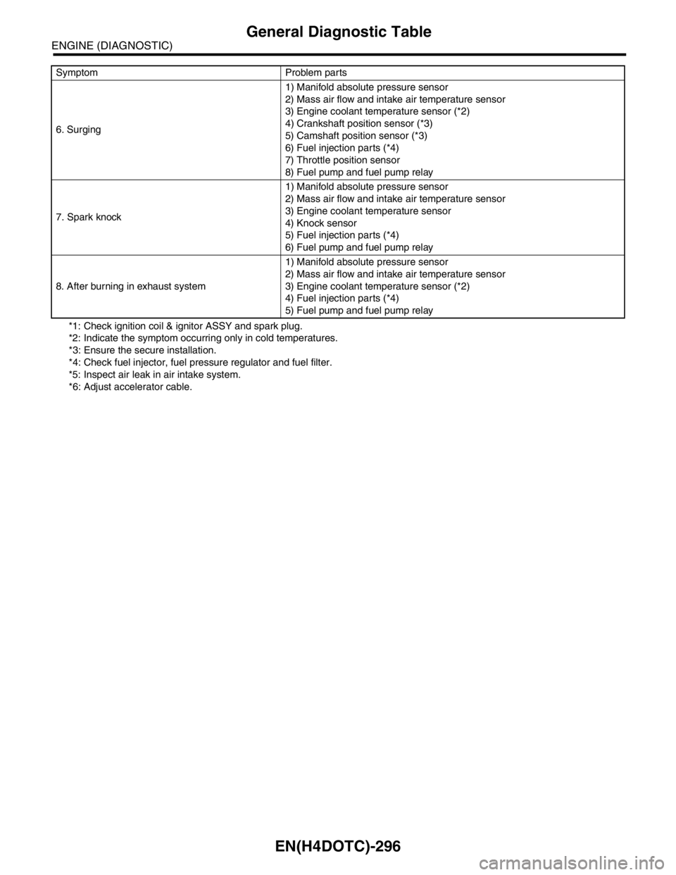
EN(H4DOTC)-296
ENGINE (DIAGNOSTIC)
General Diagnostic Table
*1: Check ignition coil & ignitor ASSY and spark plug.
*2: Indicate the symptom occurring only in cold temperatures.
*3: Ensure the secure installation.
*4: Check fuel injector, fuel pressure regulator and fuel filter.
*5: Inspect air leak in air intake system.
*6: Adjust accelerator cable. 6. Surging1) Manifold absolute pressure sensor
2) Mass air flow and intake air temperature sensor
3) Engine coolant temperature sensor (*2)
4) Crankshaft position sensor (*3)
5) Camshaft position sensor (*3)
6) Fuel injection parts (*4)
7) Throttle position sensor
8) Fuel pump and fuel pump relay
7. Spark knock1) Manifold absolute pressure sensor
2) Mass air flow and intake air temperature sensor
3) Engine coolant temperature sensor
4) Knock sensor
5) Fuel injection parts (*4)
6) Fuel pump and fuel pump relay
8. After burning in exhaust system1) Manifold absolute pressure sensor
2) Mass air flow and intake air temperature sensor
3) Engine coolant temperature sensor (*2)
4) Fuel injection parts (*4)
5) Fuel pump and fuel pump relay Symptom Problem parts
Page 1945 of 2870
FU(H4DOTC 2.5)-15
FUEL INJECTION (FUEL SYSTEM)
Intake Manifold
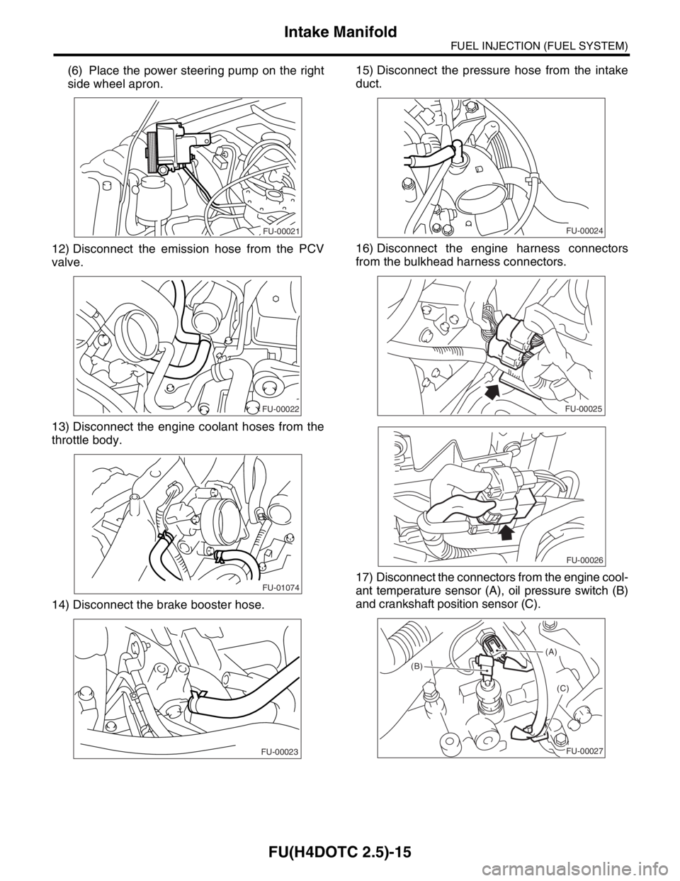
(6) Place the power steering pump on the right
side wheel apron.
12) Disconnect the emission hose from the PCV
valve.
13) Disconnect the engine coolant hoses from the
throttle body.
14) Disconnect the brake booster hose.15) Disconnect the pressure hose from the intake
duct.
16) Disconnect the engine harness connectors
from the bulkhead harness connectors.
17) Disconnect the connectors from the engine cool-
ant temperature sensor (A), oil pressure switch (B)
and crankshaft position sensor (C).
FU-00021
FU-00022
FU-01074
FU-00023
FU-00024
FU-00025
FU-00026
(A)
(B)
(C)
FU-00027