SUBARU FORESTER 2004 Service Repair Manual
FORESTER 2004
SUBARU
SUBARU
https://www.carmanualsonline.info/img/17/57426/w960_57426-0.png
SUBARU FORESTER 2004 Service Repair Manual
Trending: keyless, turn signal, warning light, sport mode, transmission, instrument panel, wipers
Page 811 of 2870
FU(H4SO)-29
FUEL INJECTION (FUEL SYSTEM)
Throttle Position Sensor
8. Throttle Position Sensor
A: REMOVAL
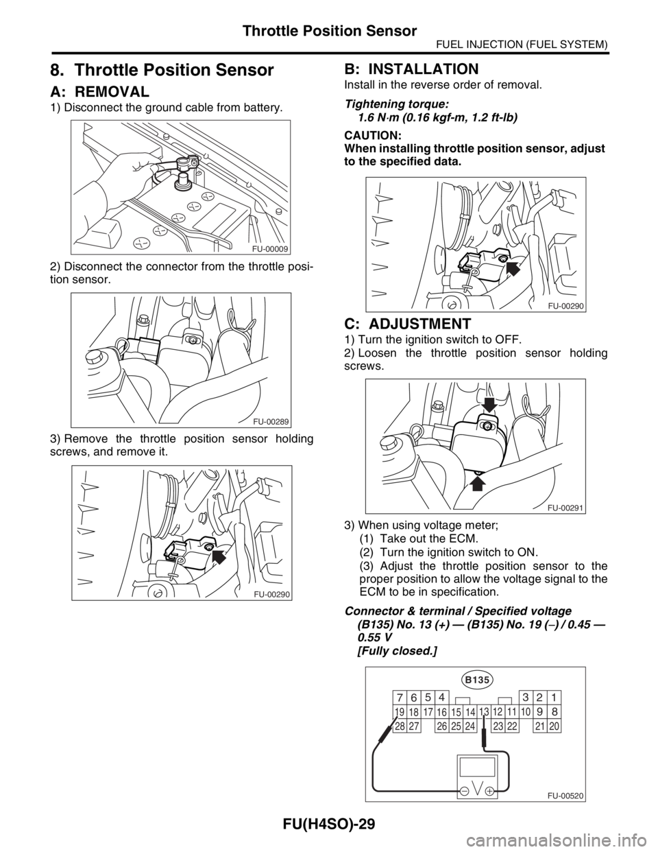
1) Disconnect the ground cable from battery.
2) Disconnect the connector from the throttle posi-
tion sensor.
3) Remove the throttle position sensor holding
screws, and remove it.
B: INSTALLATION
Install in the reverse order of removal.
Tightening torque:
1.6 N
⋅m (0.16 kgf-m, 1.2 ft-lb)
CAUTION:
When installing throttle position sensor, adjust
to the specified data.
C: ADJUSTMENT
1) Turn the ignition switch to OFF.
2) Loosen the throttle position sensor holding
screws.
3) When using voltage meter;
(1) Take out the ECM.
(2) Turn the ignition switch to ON.
(3) Adjust the throttle position sensor to the
proper position to allow the voltage signal to the
ECM to be in specification.
Connector & terminal / Specified voltage
(B135) No. 13 (+) — (B135) No. 19 (
−) / 0.45 —
0.55 V
[Fully closed.]
FU-00009
FU-00289
FU-00290
FU-00290
FU-00291
FU-00520
4
1 526
18 1516
7
891011
17
19
20121314
B135
3
2122232425262728
Page 812 of 2870
FU(H4SO)-30
FUEL INJECTION (FUEL SYSTEM)
Throttle Position Sensor
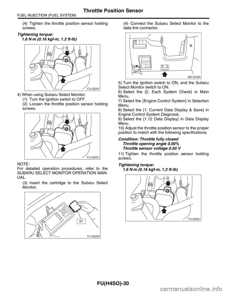
(4) Tighten the throttle position sensor holding
screws.
Tightening torque:
1.6 N
⋅m (0.16 kgf-m, 1.2 ft-lb)
4) When using Subaru Select Monitor;
(1) Turn the ignition switch to OFF.
(2) Loosen the throttle position sensor holding
screws.
NOTE:
For detailed operation procedures, refer to the
SUBARU SELECT MONITOR OPERATION MAN-
UAL.
(3) Insert the cartridge to the Subaru Select
Monitor.(4) Connect the Subaru Select Monitor to the
data link connector.
5) Turn the ignition switch to ON, and the Subaru
Select Monitor switch to ON.
6) Select the {2. Each System Check} in Main
Menu.
7) Select the {Engine Control System} in Selection
Menu.
8) Select the {1. Current Data Display & Save} in
Engine Control System Diagnosis.
9) Select the {1.12 Data Display} in Data Display
Menu.
10) Adjust the throttle position sensor to the proper
position to match with the following specifications.
Condition: Throttle fully closed
Throttle opening angle 0.00%
Throttle sensor voltage 0.50 V
11) Tighten the throttle position sensor holding
screws.
Tightening torque:
1.6 N
⋅m (0.16 kgf-m, 1.2 ft-lb)
FU-00291
FU-00291
FU-00293
ST
ME-00325
FU-00291
Page 813 of 2870
FU(H4SO)-31
FUEL INJECTION (FUEL SYSTEM)
Manifold Absolute Pressure Sensor
9. Manifold Absolute Pressure
Sensor
A: REMOVAL
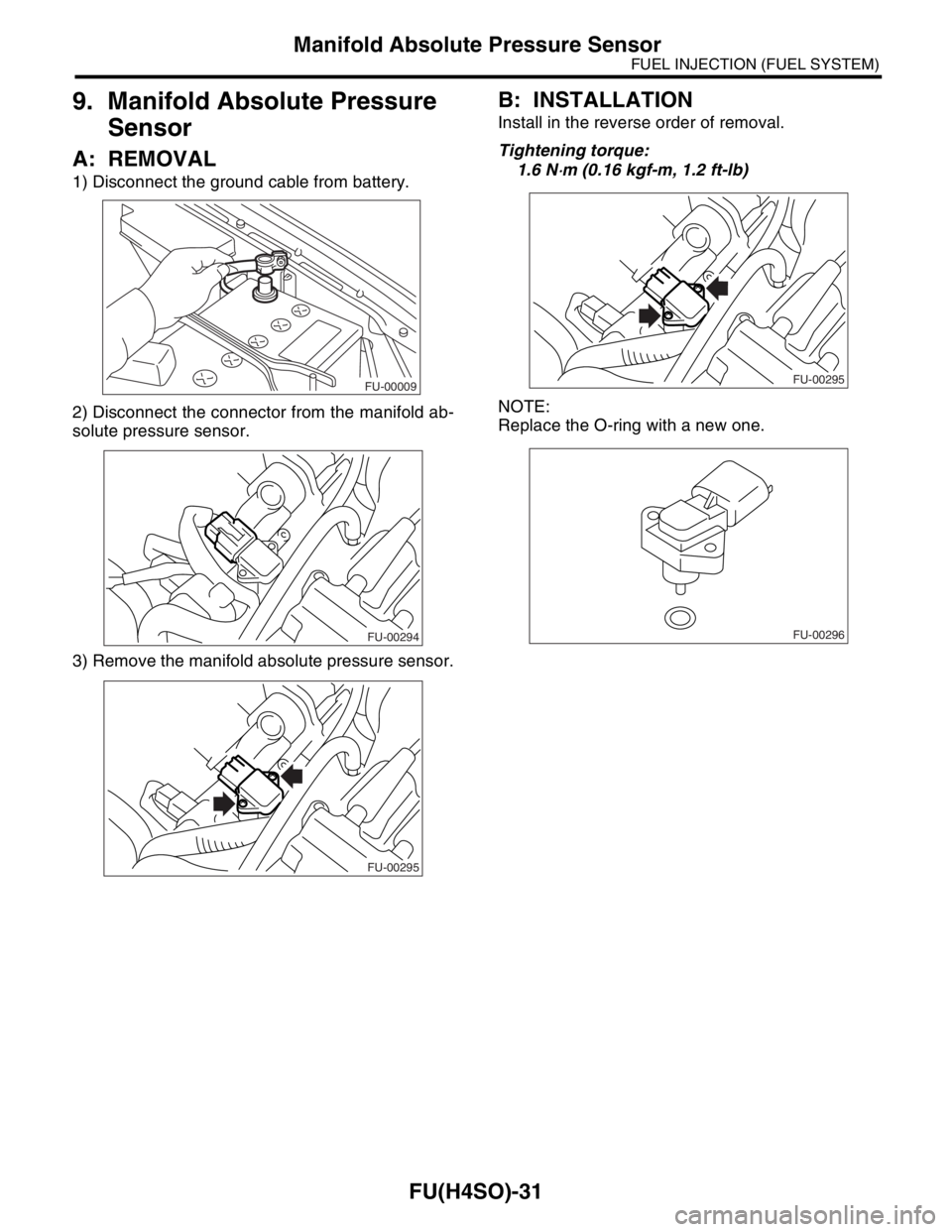
1) Disconnect the ground cable from battery.
2) Disconnect the connector from the manifold ab-
solute pressure sensor.
3) Remove the manifold absolute pressure sensor.
B: INSTALLATION
Install in the reverse order of removal.
Tightening torque:
1.6 N
⋅m (0.16 kgf-m, 1.2 ft-lb)
NOTE:
Replace the O-ring with a new one.
FU-00009
FU-00294
FU-00295
FU-00295
FU-00296
Page 814 of 2870
FU(H4SO)-32
FUEL INJECTION (FUEL SYSTEM)
Intake Air Temperature Sensor
10.Intake Air Temperature Sen-
sor
A: REMOVAL
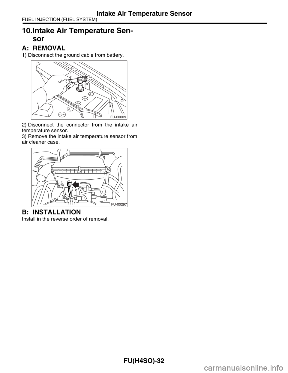
1) Disconnect the ground cable from battery.
2) Disconnect the connector from the intake air
temperature sensor.
3) Remove the intake air temperature sensor from
air cleaner case.
B: INSTALLATION
Install in the reverse order of removal.
FU-00009
FU-00297
Page 815 of 2870
FU(H4SO)-33
FUEL INJECTION (FUEL SYSTEM)
Idle Air Control Solenoid Valve
11.Idle Air Control Solenoid
Valve
A: REMOVAL
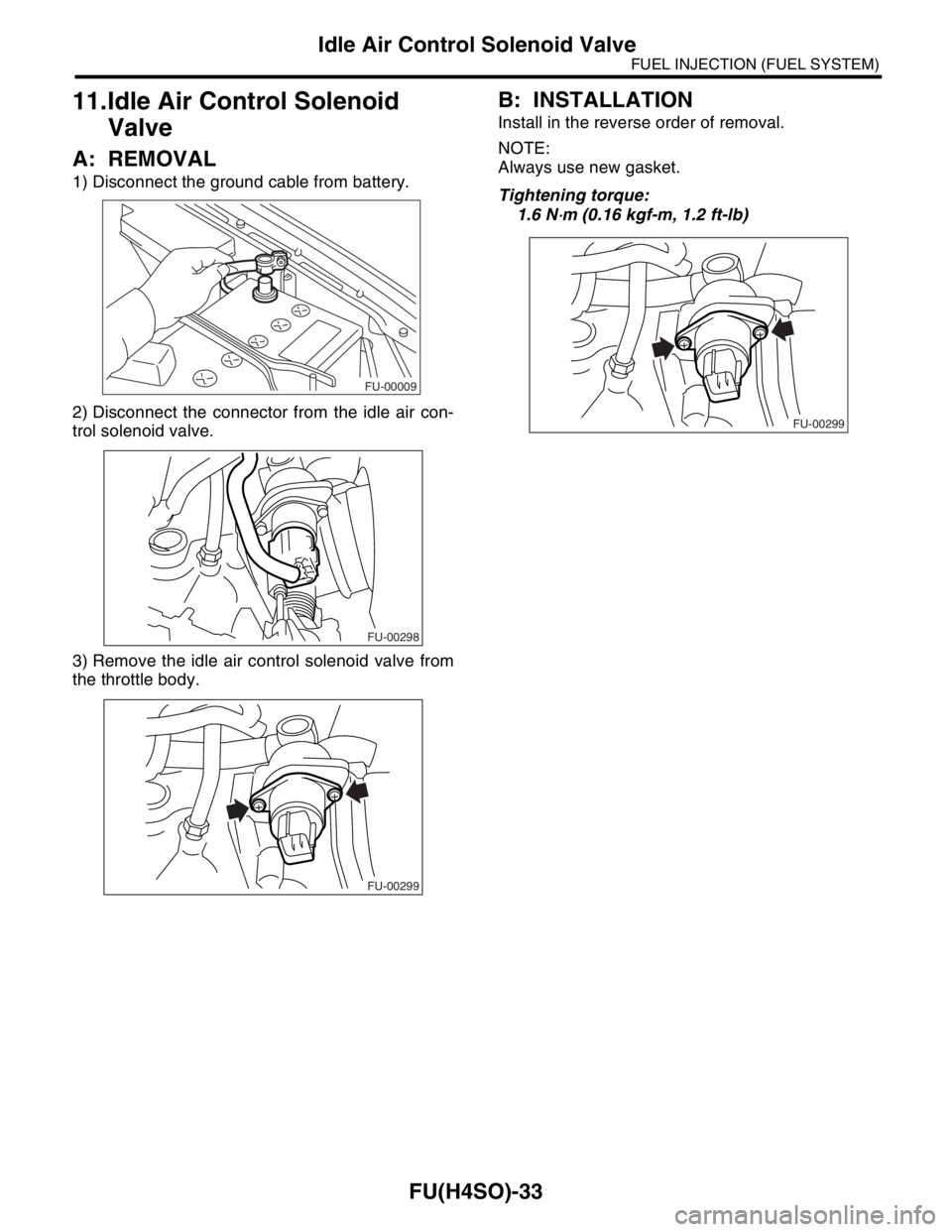
1) Disconnect the ground cable from battery.
2) Disconnect the connector from the idle air con-
trol solenoid valve.
3) Remove the idle air control solenoid valve from
the throttle body.
B: INSTALLATION
Install in the reverse order of removal.
NOTE:
Always use new gasket.
Tightening torque:
1.6 N
⋅m (0.16 kgf-m, 1.2 ft-lb)
FU-00009
FU-00298
FU-00299
FU-00299
Page 816 of 2870
FU(H4SO)-34
FUEL INJECTION (FUEL SYSTEM)
EGR Valve
12.EGR Valve
A: REMOVAL
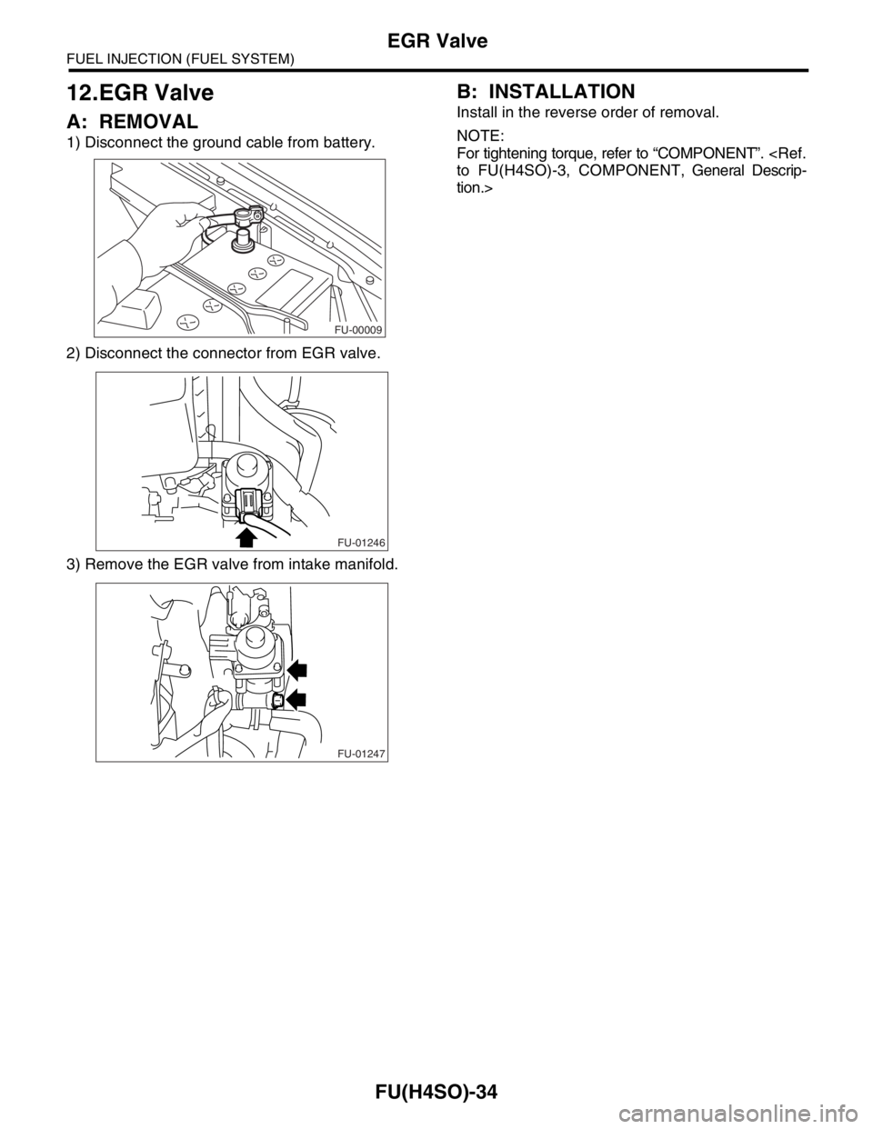
1) Disconnect the ground cable from battery.
2) Disconnect the connector from EGR valve.
3) Remove the EGR valve from intake manifold.
B: INSTALLATION
Install in the reverse order of removal.
NOTE:
For tightening torque, refer to “COMPONENT”.
to FU(H4SO)-3, COMPONENT, General Descrip-
tion.>
FU-00009
FU-01246
FU-01247
Page 817 of 2870
FU(H4SO)-35
FUEL INJECTION (FUEL SYSTEM)
Fuel Injector
13.Fuel Injector
A: REMOVAL
1. RH SIDE
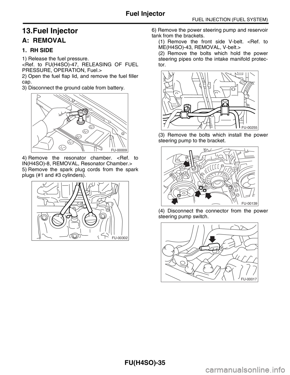
1) Release the fuel pressure.
PRESSURE, OPERATION, Fuel.>
2) Open the fuel flap lid, and remove the fuel filler
cap.
3) Disconnect the ground cable from battery.
4) Remove the resonator chamber.
IN(H4SO)-8, REMOVAL, Resonator Chamber.>
5) Remove the spark plug cords from the spark
plugs (#1 and #3 cylinders).6) Remove the power steering pump and reservoir
tank from the brackets.
(1) Remove the front side V-belt.
ME(H4SO)-43, REMOVAL, V-belt.>
(2) Remove the bolts which hold the power
steering pipes onto the intake manifold protec-
tor.
(3) Remove the bolts which install the power
steering pump to the bracket.
(4) Disconnect the connector from the power
steering pump switch.
FU-00009
FU-00302
FU-00255
FU-00139
FU-00017
Page 818 of 2870
FU(H4SO)-36
FUEL INJECTION (FUEL SYSTEM)
Fuel Injector
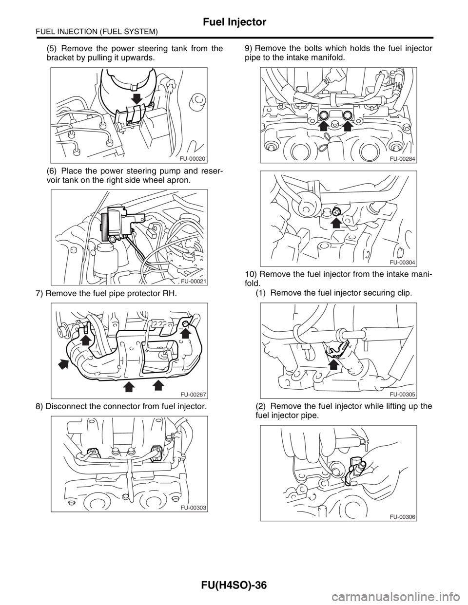
(5) Remove the power steering tank from the
bracket by pulling it upwards.
(6) Place the power steering pump and reser-
voir tank on the right side wheel apron.
7) Remove the fuel pipe protector RH.
8) Disconnect the connector from fuel injector.9) Remove the bolts which holds the fuel injector
pipe to the intake manifold.
10) Remove the fuel injector from the intake mani-
fold.
(1) Remove the fuel injector securing clip.
(2) Remove the fuel injector while lifting up the
fuel injector pipe.
FU-00020
FU-00021
FU-00267
FU-00303
FU-00284
FU-00304
FU-00305
FU-00306
Page 819 of 2870
FU(H4SO)-37
FUEL INJECTION (FUEL SYSTEM)
Fuel Injector
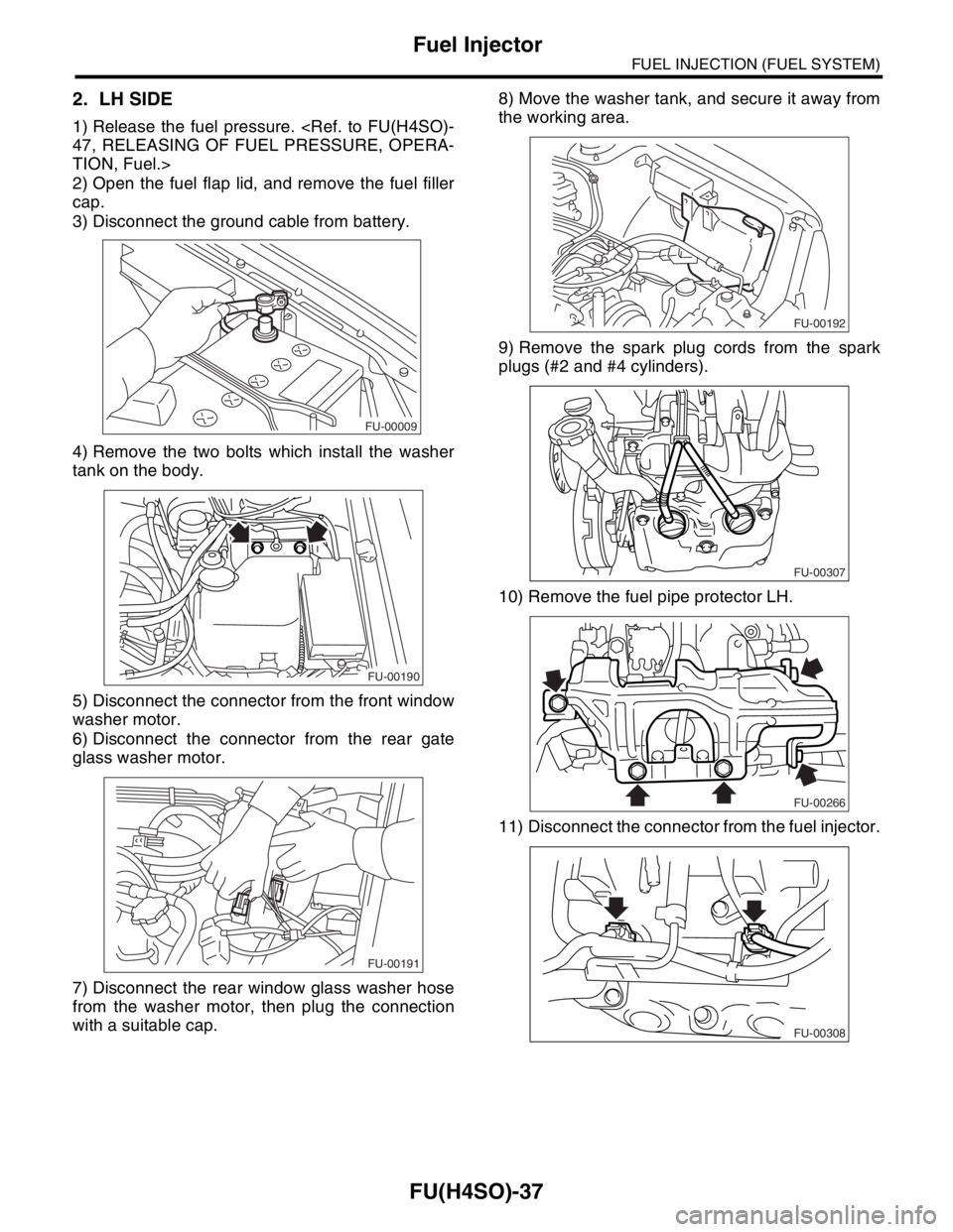
2. LH SIDE
1) Release the fuel pressure.
47, RELEASING OF FUEL PRESSURE, OPERA-
TION, Fuel.>
2) Open the fuel flap lid, and remove the fuel filler
cap.
3) Disconnect the ground cable from battery.
4) Remove the two bolts which install the washer
tank on the body.
5) Disconnect the connector from the front window
washer motor.
6) Disconnect the connector from the rear gate
glass washer motor.
7) Disconnect the rear window glass washer hose
from the washer motor, then plug the connection
with a suitable cap.8) Move the washer tank, and secure it away from
the working area.
9) Remove the spark plug cords from the spark
plugs (#2 and #4 cylinders).
10) Remove the fuel pipe protector LH.
11) Disconnect the connector from the fuel injector.
FU-00009
FU-00190
FU-00191
FU-00192
FU-00307
FU-00266
FU-00308
Page 820 of 2870
FU(H4SO)-38
FUEL INJECTION (FUEL SYSTEM)
Fuel Injector
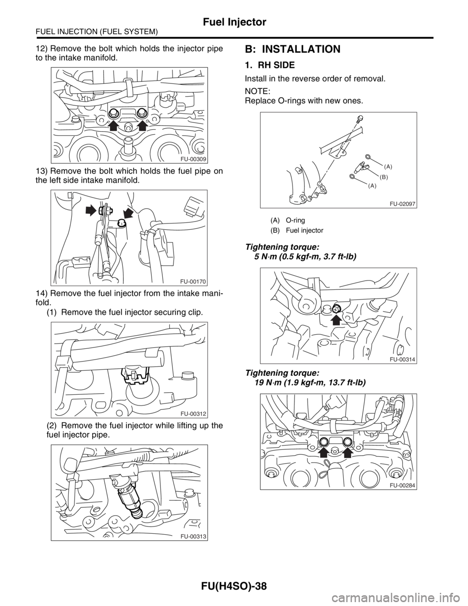
12) Remove the bolt which holds the injector pipe
to the intake manifold.
13) Remove the bolt which holds the fuel pipe on
the left side intake manifold.
14) Remove the fuel injector from the intake mani-
fold.
(1) Remove the fuel injector securing clip.
(2) Remove the fuel injector while lifting up the
fuel injector pipe.B: INSTALLATION
1. RH SIDE
Install in the reverse order of removal.
NOTE:
Replace O-rings with new ones.
Tightening torque:
5 N
⋅m (0.5 kgf-m, 3.7 ft-lb)
Tightening torque:
19 N
⋅m (1.9 kgf-m, 13.7 ft-lb)
FU-00309
FU-00170
FU-00312
FU-00313
(A) O-ring
(B) Fuel injector
FU-02097
(A)
(A)(B)
FU-00314
FU-00284
Trending: seat adjustment, clock setting, wiring diagram, catalytic converter, spare wheel, child seat, fuel pressure


