SUBARU FORESTER 2004 Service Repair Manual
FORESTER 2004
SUBARU
SUBARU
https://www.carmanualsonline.info/img/17/57426/w960_57426-0.png
SUBARU FORESTER 2004 Service Repair Manual
Trending: battery, maintenance schedule, combination meter, coolant reservoir, driver seat adjustment, Engine mount, wheel size
Page 781 of 2870
PM-44
PERIODIC MAINTENANCE SERVICE
Steering System (Power Steering)
Page 782 of 2870
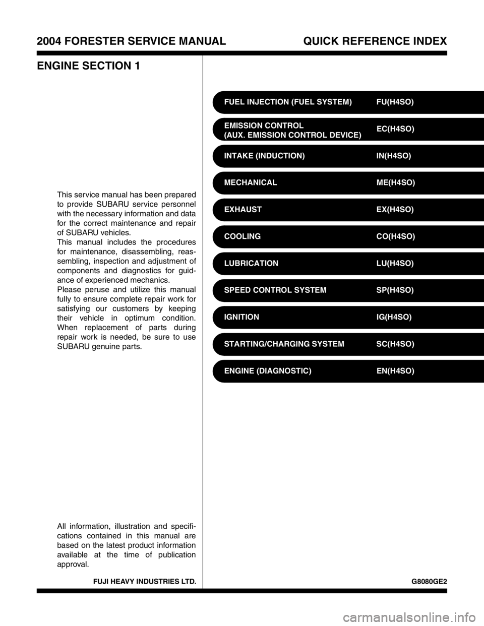
FUJI HEAVY INDUSTRIES LTD. G8080GE2
2004 FORESTER SERVICE MANUAL QUICK REFERENCE INDEX
ENGINE SECTION 1
This service manual has been prepared
to provide SUBARU service personnel
with the necessary information and data
for the correct maintenance and repair
of SUBARU vehicles.
This manual includes the procedures
for maintenance, disassembling, reas-
sembling, inspection and adjustment of
components and diagnostics for guid-
ance of experienced mechanics.
Please peruse and utilize this manual
fully to ensure complete repair work for
satisfying our customers by keeping
their vehicle in optimum condition.
When replacement of parts during
repair work is needed, be sure to use
SUBARU genuine parts.
All information, illustration and specifi-
cations contained in this manual are
based on the latest product information
available at the time of publication
approval.FUEL INJECTION (FUEL SYSTEM) FU(H4SO)
EMISSION CONTROL
(AUX. EMISSION CONTROL DEVICE)EC(H4SO)
INTAKE (INDUCTION) IN(H4SO)
MECHANICAL ME(H4SO)
EXHAUST EX(H4SO)
COOLING CO(H4SO)
LUBRICATION LU(H4SO)
SPEED CONTROL SYSTEM SP(H4SO)
IGNITION IG(H4SO)
STARTING/CHARGING SYSTEM SC(H4SO)
ENGINE (DIAGNOSTIC) EN(H4SO)
Page 783 of 2870

FUEL INJECTION (FUEL SYSTEM)
FU(H4SO)
Page
1. General Description ....................................................................................2
2. Throttle Body .............................................................................................13
3. Intake Manifold ..........................................................................................14
4. Engine Coolant Temperature Sensor........................................................25
5. Crankshaft Position Sensor.......................................................................26
6. Camshaft Position Sensor.........................................................................27
7. Knock Sensor ............................................................................................28
8. Throttle Position Sensor ............................................................................29
9. Manifold Absolute Pressure Sensor ..........................................................31
10. Intake Air Temperature Sensor .................................................................32
11. Idle Air Control Solenoid Valve .................................................................33
12. EGR Valve ................................................................................................34
13. Fuel Injector ..............................................................................................35
14. Front Oxygen (A/F) Sensor .......................................................................40
15. Rear Oxygen Sensor.................................................................................42
16. Engine Control Module (ECM) ..................................................................44
17. Main Relay ................................................................................................45
18. Fuel Pump Relay.......................................................................................46
19. Fuel ...........................................................................................................47
20. Fuel Tank ..................................................................................................48
21. Fuel Filler Pipe ..........................................................................................51
22. Fuel Pump .................................................................................................55
23. Fuel Level Sensor .....................................................................................57
24. Fuel Sub Level Sensor ..............................................................................58
25. Fuel Filter ..................................................................................................60
26. Fuel Cut Valve...........................................................................................61
27. Fuel Damper Valve ...................................................................................62
28. Fuel Delivery, Return and Evaporation Lines............................................63
29. Fuel System Trouble in General ...............................................................66
Page 784 of 2870
FU(H4SO)-2
FUEL INJECTION (FUEL SYSTEM)
General Description
1. General Description
A: SPECIFICATION
ModelSpecification
Fuel tankCapacity 602 (15.9 US gal, 13.2 Imp gal)
Location Under rear seat
Fuel pumpType Impeller
Shutoff discharge pressure
370 — 677 kPa (3.77 — 6.9 kg/cm
2, 53.6 — 98 psi)
Discharge flowMore than 652 (17.2 US gal, 14.3 Imp gal) /h
[12 V at 300 kPa (3.06 kg/cm
2, 43.5 psi)]
Fuel filterCartridge type
Page 785 of 2870
FU(H4SO)-3
FUEL INJECTION (FUEL SYSTEM)
General Description
B: COMPONENT
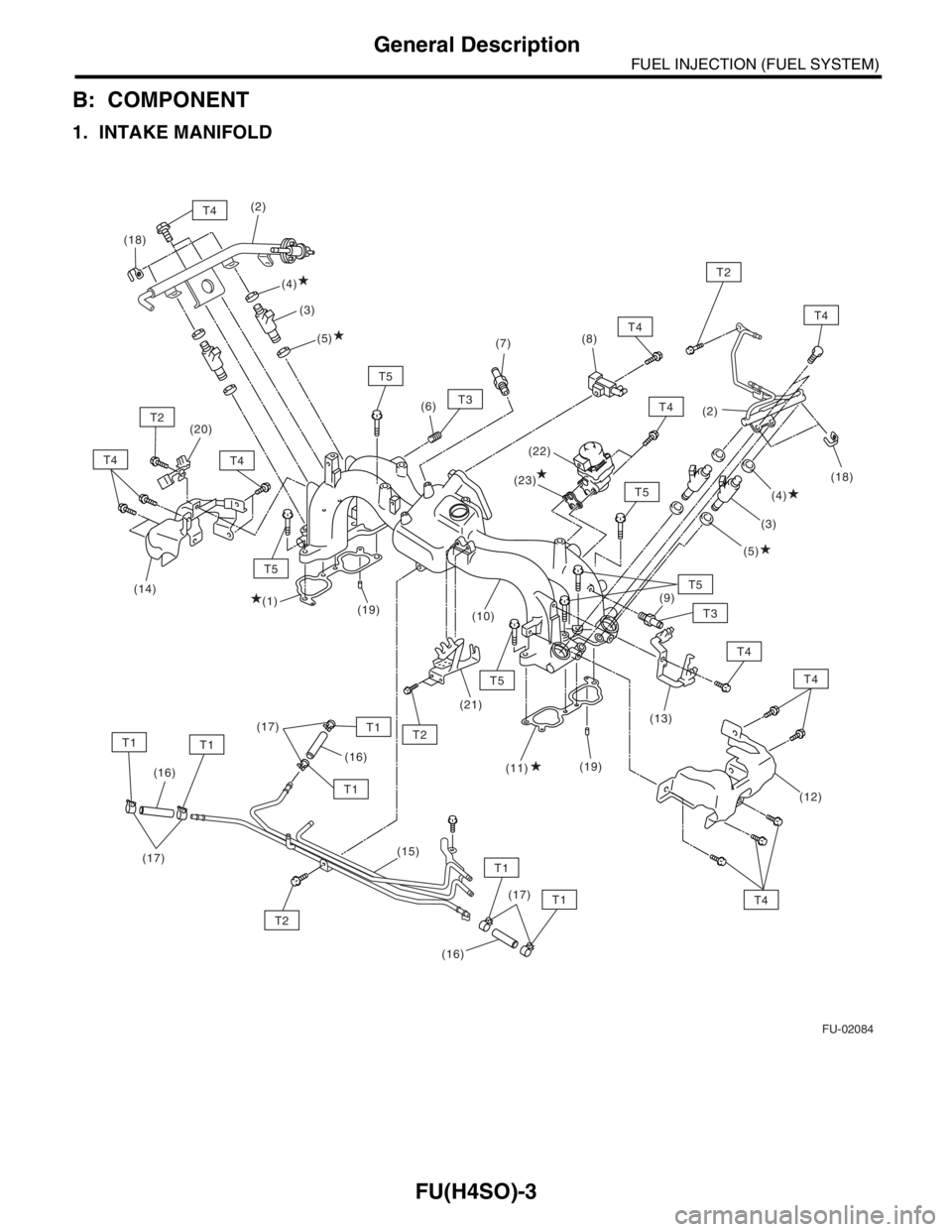
1. INTAKE MANIFOLD
FU-02084
T2
T2
T1T1
T1
T1
T1
T1
T5
T4T4
T4
T2
T5
T4
T4
T3
T3
T5
T5
T5T4
T4
T4
T2
T4
(5) (3) (2)
(4)
(1)(4)
(3)
(5) (2)
(19) (20)(6)(7)(8)
(9)
(16)(16)
(16)(19) (21)
(17)(17)(13)
(15)
(17)(12) (11) (18)
(14)
(10)(22)
(18)
(23)
Page 786 of 2870
FU(H4SO)-4
FUEL INJECTION (FUEL SYSTEM)
General Description
(1) Intake manifold gasket RH (11) Intake manifold gasket LH (21) Accelerator cable bracket
(2) Fuel injector pipe (12) Fuel pipe protector LH (22) EGR valve
(3) Fuel injector (13) Plug cord holder LH (23) Gasket
(4) O-ring (14) Fuel pipe protector RH
(5) O-ring (15) Fuel pipe ASSYTightening torque: N
⋅m (kgf-m, ft-lb)
(6) Plug (16) Fuel hoseT1: 1.5 (0.15, 1.1)
(7) PCV valve (17) ClipT2: 6.4 (0.7, 4.7)
(8) Purge control solenoid valve (18) ClipT3: 17 (1.7, 12.5)
(9) Nipple (19) Guide pinT4: 19 (1.9, 13.7)
(10) Intake manifold (20) Plug cord holder RHT5: 25 (2.5, 18.1)
Page 787 of 2870
FU(H4SO)-5
FUEL INJECTION (FUEL SYSTEM)
General Description
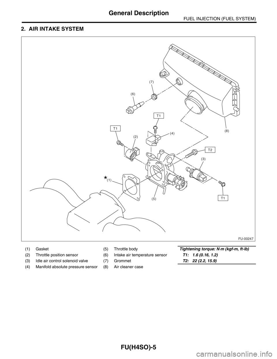
2. AIR INTAKE SYSTEM
(1) Gasket (5) Throttle bodyTightening torque: N⋅m (kgf-m, ft-lb)
(2) Throttle position sensor (6) Intake air temperature sensorT1: 1.6 (0.16, 1.2)
(3) Idle air control solenoid valve (7) GrommetT2: 22 (2.2, 15.9)
(4) Manifold absolute pressure sensor (8) Air cleaner case
FU-00247
(2)
(3) (4)
(5) (1)
T1
T1
T1
T2
(8) (6)(7)
Page 788 of 2870
FU(H4SO)-6
FUEL INJECTION (FUEL SYSTEM)
General Description
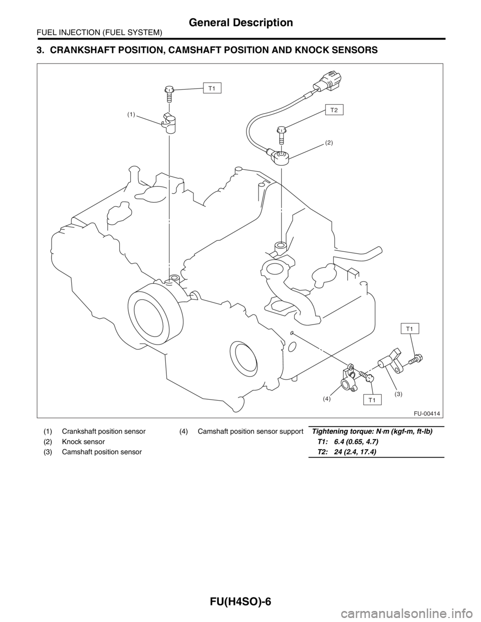
3. CRANKSHAFT POSITION, CAMSHAFT POSITION AND KNOCK SENSORS
(1) Crankshaft position sensor (4) Camshaft position sensor supportTightening torque: N⋅m (kgf-m, ft-lb)
(2) Knock sensorT1: 6.4 (0.65, 4.7)
(3) Camshaft position sensorT2: 24 (2.4, 17.4)
FU-00414
T1
(1)
(2)
T1
T1(3)
(4)
T2
Page 789 of 2870
FU(H4SO)-7
FUEL INJECTION (FUEL SYSTEM)
General Description
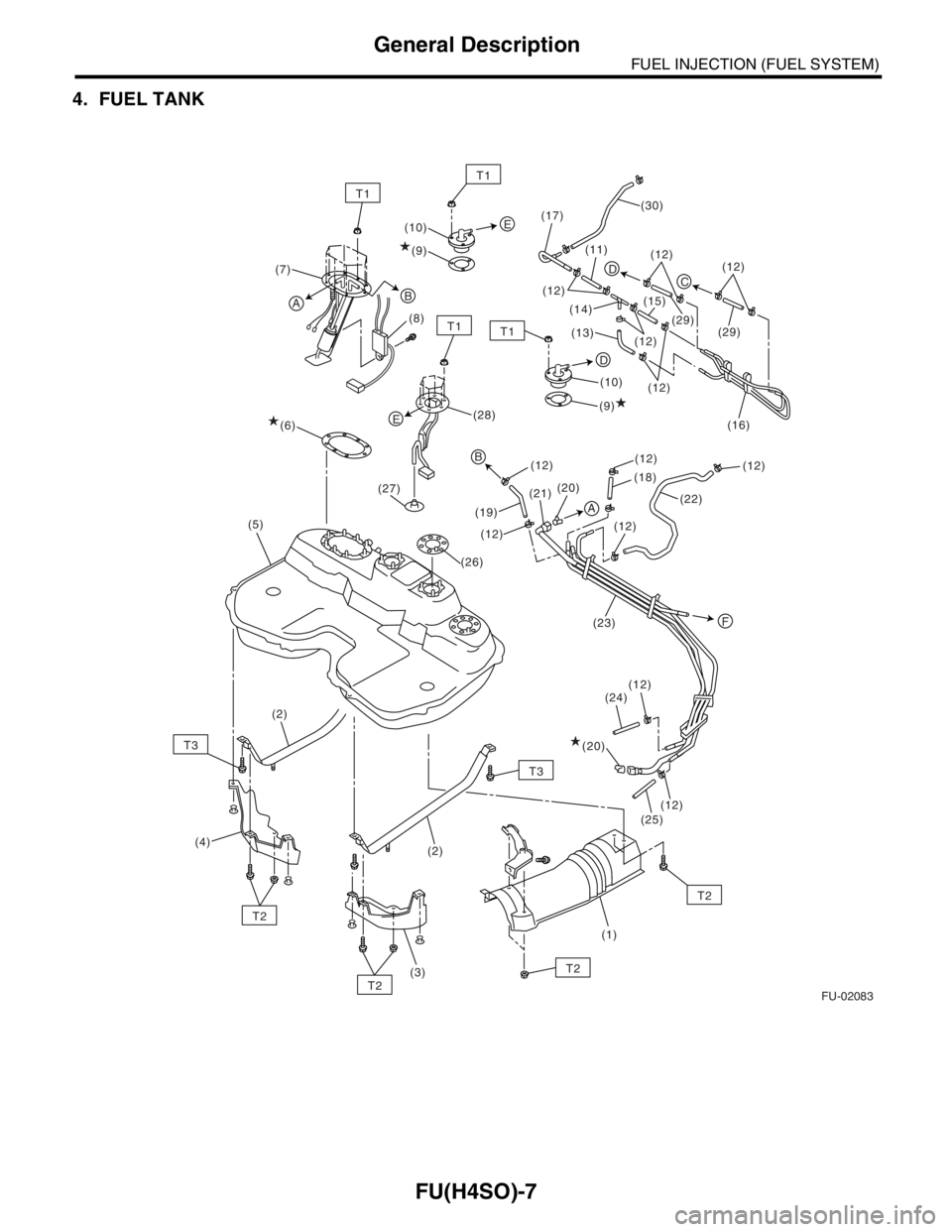
4. FUEL TANK
FU-02083
T1
T1
T3
T2
T2
T2
T2
T3 (7)
(6)(8)(9) (10)
(10)
(9)
(19)(18)
(22) (12)(12)
(12)
(23)
(12)
(12) (24)
(25) (12)(21)(20)
(1) (2)
(3) (4)(2) (5)
AB
(28)
(29)
(16)
E
F
A
B
T1T1
DC
E
D
(20)
(12)(12)
(12)
(12)
(12)
(29)
(13) (14)(11) (17)(30)
(15)
(27)
(26)
(12)
Page 790 of 2870
FU(H4SO)-8
FUEL INJECTION (FUEL SYSTEM)
General Description
(1) Heat shield cover (13) Evaporation hose B (25) Fuel return hose B
(2) Fuel tank band (14) Joint pipe (26) Fuel sub level sensor gasket
(3) Protector LH (15) Evaporation hose C (27) Jet pump filter
(4) Protector RH (16) Evaporation pipe ASSY (28) Fuel sub level sensor
(5) Fuel tank (17) Evaporation pipe (29) Evaporation hose G
(6) Fuel pump gasket (18) Evaporation hose D (30) Evaporation hose H
(7) Fuel pump ASSY (19) Fuel return hose A
(8) Fuel level sensor (20) RetainerTightening torque: N
⋅m (kgf-m, ft-lb)
(9) Fuel cut valve gasket (21) Quick connectorT1: 4.4 (0.45, 3.3)
(10) Fuel cut valve (22) Evaporation hose ET2: 7.4 (0.75, 5.4)
(11) Evaporation hose A (23) Fuel pipe ASSYT3: 33 (3.4, 24.3)
(12) Clip (24) Evaporation hose F
Trending: air suspension, engine repair, oil change, door lock, fuel cap release, cruise control, washer fluid


