Shifter SUBARU FORESTER 2004 Service Repair Manual
[x] Cancel search | Manufacturer: SUBARU, Model Year: 2004, Model line: FORESTER, Model: SUBARU FORESTER 2004Pages: 2870, PDF Size: 38.67 MB
Page 2713 of 2870

MANUAL TRANSMISSION AND
DIFFERENTIAL
5MT
Page
1. General Description ....................................................................................2
2. Transmission Gear Oil ..............................................................................31
3. Manual Transmission Assembly ...............................................................32
4. Transmission Mounting System ................................................................39
5. Oil Seal......................................................................................................41
6. Differential Side Retainer Oil Seal.............................................................42
7. Switches and Harness ..............................................................................43
8. Vehicle Speed Sensor...............................................................................46
9. Preparation for Overhaul ...........................................................................47
10. Oil Pump ...................................................................................................48
11. Transfer Case and Extension Case Assembly..........................................50
12. Transfer Drive Gear ..................................................................................54
13. Transfer Driven Gear ................................................................................56
14. Center Differential .....................................................................................58
15. Reverse Check Sleeve..............................................................................59
16. Transmission Case ...................................................................................62
17. Main Shaft Assembly For Single-Range ...................................................69
18. Main Shaft Assembly For Dual-Range ......................................................77
19. Input Shaft Assembly ................................................................................83
20. Drive Pinion Shaft Assembly .....................................................................87
21. Front Differential Assembly .......................................................................96
22. Speedometer Gear..................................................................................103
23. Reverse Idler Gear ..................................................................................104
24. Shifter Fork and Rod ...............................................................................106
25. Counter Gear ..........................................................................................109
26. General Diagnostic..................................................................................111
Page 2716 of 2870

5MT-4
MANUAL TRANSMISSION AND DIFFERENTIAL
General Description
7. REVERSE IDLER GEAR
Adjustment of reverse idler gear position
Reverse idler gear to transmission case (LH)
wall clearance :
6.0 — 7.5 mm (0.236 — 0.295 in)
After installing a suitable reverse shifter lever, ad-
just the clearance using washers.
Reverse idler gear to transmission case wall
clearance:
0 — 0.5 mm (0 — 0.020 in)
8. SHIFTER FORK AND ROD
Select the suitable shifter forks so that both cou-
pling sleeve and reverse driven gear are positioned
in the center of their synchromesh mechanisms.
Rod end clearance :
A: 1st-2nd — 3rd-4th
0.4 — 1.4 mm (0.016 — 0.055 in)
B: 3rd-4th — 5th
0.5 — 1.3 mm (0.020 — 0.051 in)
9. TRANSFER CASE OR REAR CASE
Neutral position adjustment
Reverse check plate adjustment
Reverse shifter lever
Part No. Mark Remarks
32820AA070 7 Further from case wall
32820AA080 8 Standard
32820AA090 9 Closer to the case wall
Washer (20.5×26×t)
Par t No.Thickness
mm (in)Par t No.Thickness
mm (in)
803020151 0.4 (0.016) 803020154 1.9 (0.075)
803020152 1.1 (0.043) 803020155 2.3 (0.091)
803020153 1.5 (0.059) — —
1st-2nd shifter fork
Part No. Mark Remarks
32804AA060 1Approach to 1st gear
by 0.2 mm (0.008 in)
32804AA070 No mark Standard
32804AA080 3 Approach to 2nd gear
by 0.2 mm (0.008 in)
3rd-4th shifter fork
Part No. Mark Remarks
32810AA061 1Approach to 4th gear
by 0.2 mm (0.008 in)
32810AA071 No mark Standard
32810AA101 3 Approach to 3rd gear
by 0.2 mm (0.008 in)
5th shifter fork (Non-turbo)
Part No. Mark Remarks
32812AA201 7Approach to 5th gear
by 0.2 mm (0.008 in)
32812AA211 No mark Standard
32812AA221 9Become distant from
5th gear by 0.2 mm
(0.008 in)
5th shifter fork (Turbo)
Part No. Mark Remarks
32812AA231 7Approach to 5th gear
by 0.2 mm (0.008 in)
32812AA241 No mark Standard
32812AA251 9Become distant from
5th gear by 0.2 mm
(0.008 in)
Adjustment shim
Part No. Thickness mm (in)
32190AA000 0.15 (0.0059)
32190AA010 0.30 (0.0118)
Reverse accent shaft
Part No. Mark Remarks
32188AA130 SNeutral position is
closer to 1st.
32188AA140 T Standard
32188AA150 UNeutral position is
closer to reverse gear.
Reverse check plate
Par t No. Mar kAngle
θRemarks
32189AA000 0 28°Arm stops closer to
5th gear.
32189AA010 1 31°Arm stops closer to
5th gear.
33189AA020 2 34°Arm stops in the cen-
ter.
32189AA030 3 37°Arm stops closer to
reverse gear.
32189AA040 4 40°Arm stops closer to
reverse gear.
Page 2723 of 2870
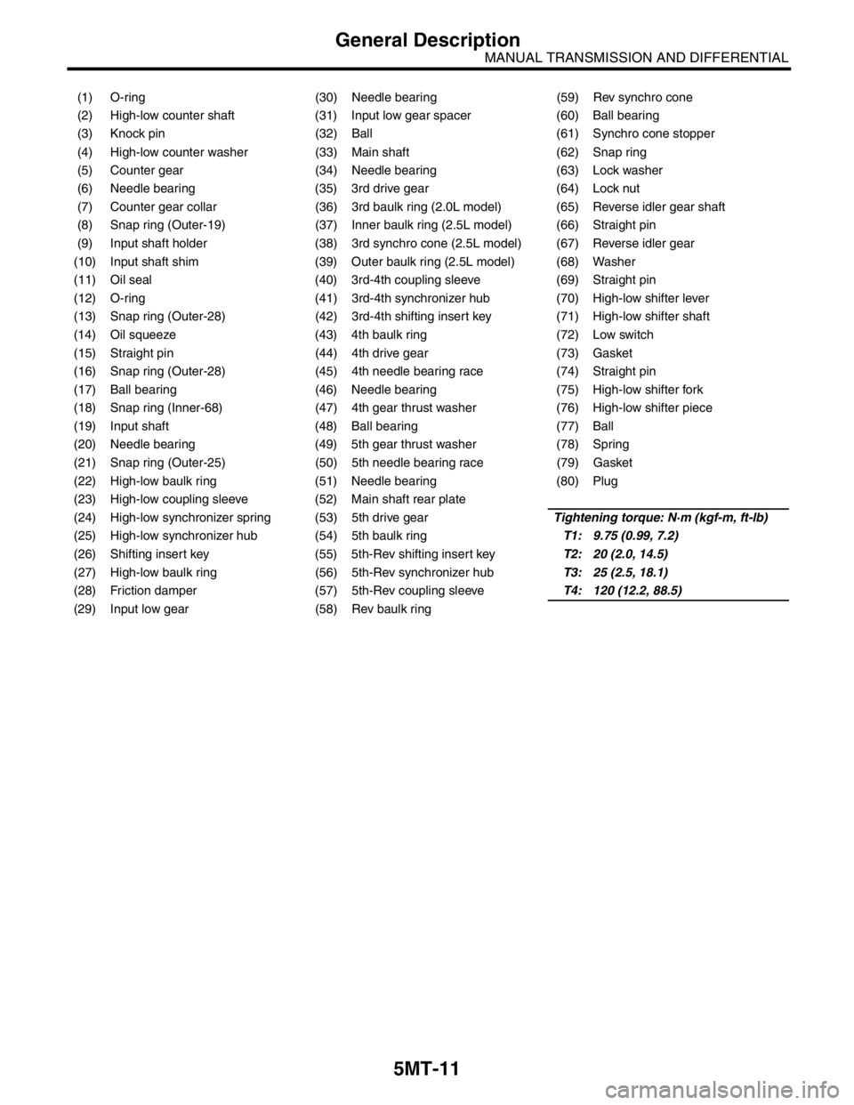
5MT-11
MANUAL TRANSMISSION AND DIFFERENTIAL
General Description
(1) O-ring (30) Needle bearing (59) Rev synchro cone
(2) High-low counter shaft (31) Input low gear spacer (60) Ball bearing
(3) Knock pin (32) Ball (61) Synchro cone stopper
(4) High-low counter washer (33) Main shaft (62) Snap ring
(5) Counter gear (34) Needle bearing (63) Lock washer
(6) Needle bearing (35) 3rd drive gear (64) Lock nut
(7) Counter gear collar (36) 3rd baulk ring (2.0L model) (65) Reverse idler gear shaft
(8) Snap ring (Outer-19) (37) Inner baulk ring (2.5L model) (66) Straight pin
(9) Input shaft holder (38) 3rd synchro cone (2.5L model) (67) Reverse idler gear
(10) Input shaft shim (39) Outer baulk ring (2.5L model) (68) Washer
(11) Oil seal (40) 3rd-4th coupling sleeve (69) Straight pin
(12) O-ring (41) 3rd-4th synchronizer hub (70) High-low shifter lever
(13) Snap ring (Outer-28) (42) 3rd-4th shifting insert key (71) High-low shifter shaft
(14) Oil squeeze (43) 4th baulk ring (72) Low switch
(15) Straight pin (44) 4th drive gear (73) Gasket
(16) Snap ring (Outer-28) (45) 4th needle bearing race (74) Straight pin
(17) Ball bearing (46) Needle bearing (75) High-low shifter fork
(18) Snap ring (Inner-68) (47) 4th gear thrust washer (76) High-low shifter piece
(19) Input shaft (48) Ball bearing (77) Ball
(20) Needle bearing (49) 5th gear thrust washer (78) Spring
(21) Snap ring (Outer-25) (50) 5th needle bearing race (79) Gasket
(22) High-low baulk ring (51) Needle bearing (80) Plug
(23) High-low coupling sleeve (52) Main shaft rear plate
(24) High-low synchronizer spring (53) 5th drive gearTightening torque: N·m (kgf-m, ft-lb)
(25) High-low synchronizer hub (54) 5th baulk ringT1: 9.75 (0.99, 7.2)
(26) Shifting insert key (55) 5th-Rev shifting insert keyT2: 20 (2.0, 14.5)
(27) High-low baulk ring (56) 5th-Rev synchronizer hubT3: 25 (2.5, 18.1)
(28) Friction damper (57) 5th-Rev coupling sleeveT4: 120 (12.2, 88.5)
(29) Input low gear (58) Rev baulk ring
Page 2724 of 2870
5MT-12
MANUAL TRANSMISSION AND DIFFERENTIAL
General Description
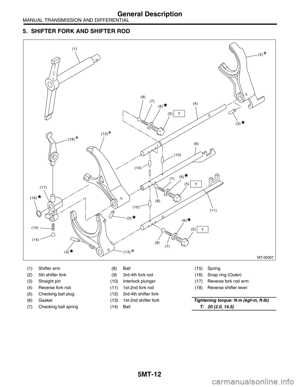
5. SHIFTER FORK AND SHIFTER ROD
(1) Shifter arm (8) Ball (15) Spring
(2) 5th shifter fork (9) 3rd-4th fork rod (16) Snap ring (Outer)
(3) Straight pin (10) Interlock plunger (17) Reverse fork rod arm
(4) Reverse fork rod (11) 1st-2nd fork rod (18) Reverse shifter lever
(5) Checking ball plug (12) 3rd-4th shifter fork
(6) Gasket (13) 1st-2nd shifter forkTightening torque: N·m (kgf-m, ft-lb)
(7) Checking ball spring (14) BallT: 20 (2.0, 14.5)
MT-00007
T
T
T (1)
(2)
(3)
(3)(3) (4)
(5)
(5)
(5) (6)
(6) (6) (7)
(7)
(7) (8)
(8)(8)(9)
(10)(10)
(10)
(11) (12)
(13) (14) (15) (16)(17)(18)
Page 2729 of 2870
5MT-17
MANUAL TRANSMISSION AND DIFFERENTIAL
General Description
C: CAUTION
Wear working clothing, including a cap, protec-
tive goggles, and protective shoes during opera-
tion.
Remove contamination including dirt and corro-
sion before removal, installation, and disassembly.
Keep the disassembled parts in order and pro-
tect them from dust or dirt.
Until the oil pan is removed, do not place with the
oil pan side facing up to prevent foreign matter from
entering the valve body.
Before removal, installation or disassembly, be
sure to clarify the failure. Avoid unnecessary re-
moval, installation, disassembly and replacement.
When disassembling the case and other light al-
loy parts, use a plastic hammer to force it apart. Do
not pry it apart with a screwdriver or other tool.
Be careful not to burn your hands, because each
part on the vehicle is hot after running. Use SUBARU genuine gear oil, grease etc. or
the equivalent. Do not mix gear oil, grease etc. with
that of another grade or from other manufacturers.
Be sure to tighten fasteners including bolts and
nuts to the specified torque.
Place shop jacks or rigid racks at the specified
points.
Apply gear oil onto sliding or revolution surfaces
before installation.
Replace deformed or otherwise damaged snap
rings with new ones.
Before installing O-rings or oil seals, apply suffi-
cient amount of gear oil to avoid damage and defor-
mation.
Be careful not to incorrectly install or fail to install
O-rings, snap rings and other such parts.
Before securing a part on a vise, place cushion-
ing material such as wood blocks, aluminum plate,
or shop cloth between the part and the vis e.
Avoid damaging the mating surface of the case.
Before applying sealant, completely remove the
old seal.
D: PREPARATION TOOL
1. SPECIAL TOOL
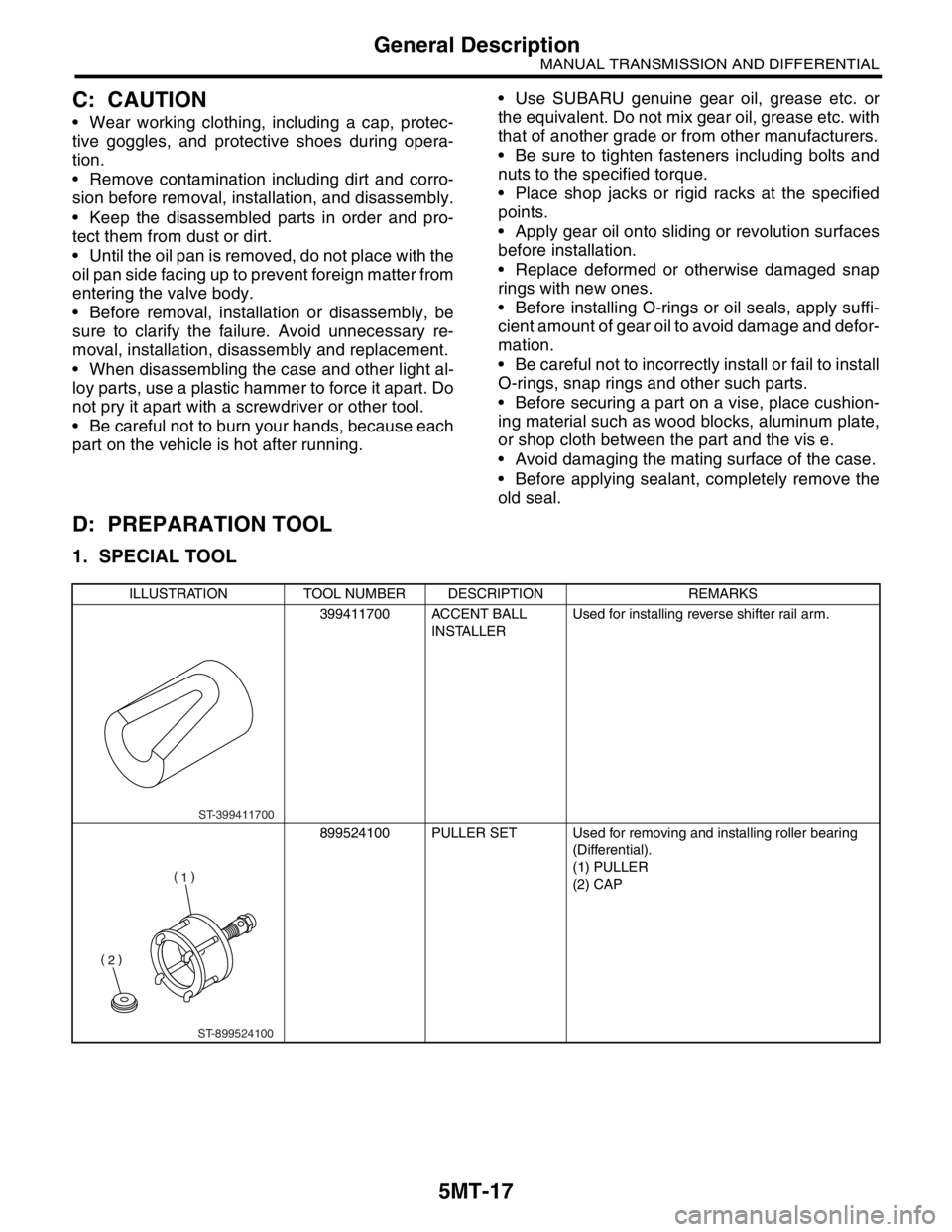
ILLUSTRATION TOOL NUMBER DESCRIPTION REMARKS
399411700 ACCENT BALL
INSTALLERUsed for installing reverse shifter rail arm.
899524100 PULLER SET Used for removing and installing roller bearing
(Differential).
(1) PULLER
(2) CAP
ST-399411700
ST-899524100
Page 2762 of 2870

5MT-50
MANUAL TRANSMISSION AND DIFFERENTIAL
Transfer Case and Extension Case Assembly
11.Transfer Case and Extension
Case Assembly
A: REMOVAL
1) Remove the manual transmission assembly
from vehicle.
2) Remove the back-up light switch and neutral po-
sition switch.
3) Remove the transfer case with extension case
assembly.
4) Remove the shifter arm.
5) Remove the extension case assembly.
B: INSTALLATION
1) Install the center differential and transfer driven
gear into transfer case.2) Remove the bearing outer race from extension
case.
3) While pressing the bearing outer race horizontal-
ly, turn the driven shaft ten rotations.
4) Measure the height “W” between transfer case
and taper roller bearing on the transfer driven gear.
5) Measure the depth “X”.
NOTE:
Measure with bearing cone and thrust washer re-
moved.
6) Calculate the space “t” using the following equa-
tion: t = X−W+0.2 to 0.3 mm (0.008 to 0.012 in)
7) Select the nearest washer in the following table:
Standard clearance between thrust washer and
taper roller bearing:
0.2 — 0.3 mm (0.008 — 0.012 in)
NOTE:
Set the clearance within standard clearance.
MT-00116
MT-00117
MT-00118
(A) Bearing outer race
(B) Extension case
MT-00119
(B)
(A)
MT-00120
W
MT-00121
X
Page 2764 of 2870
5MT-52
MANUAL TRANSMISSION AND DIFFERENTIAL
Transfer Case and Extension Case Assembly
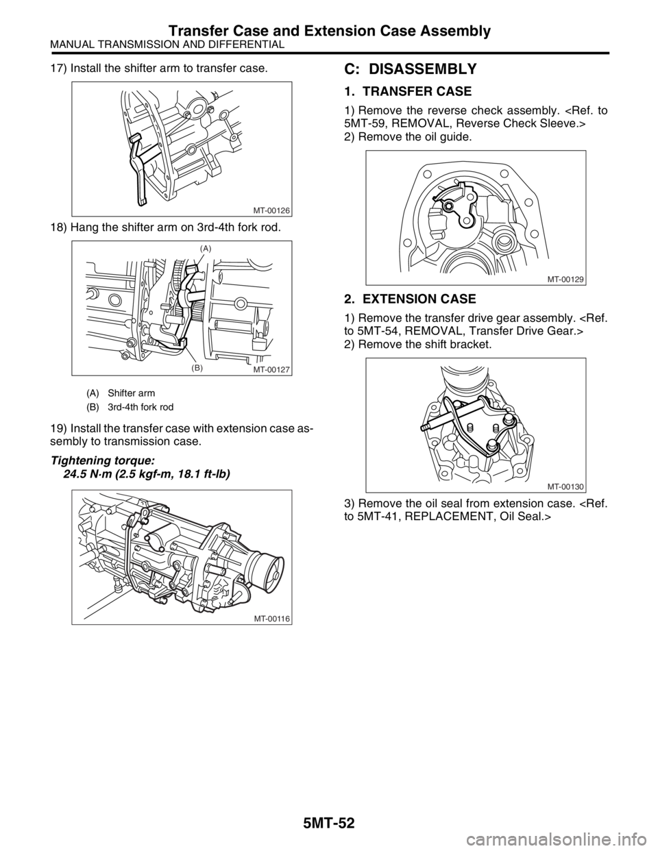
17) Install the shifter arm to transfer case.
18) Hang the shifter arm on 3rd-4th fork rod.
19) Install the transfer case with extension case as-
sembly to transmission case.
Tightening torque:
24.5 N·m (2.5 kgf-m, 18.1 ft-lb)C: DISASSEMBLY
1. TRANSFER CASE
1) Remove the reverse check assembly.
2) Remove the oil guide.
2. EXTENSION CASE
1) Remove the transfer drive gear assembly.
2) Remove the shift bracket.
3) Remove the oil seal from extension case.
(A) Shifter arm
(B) 3rd-4th fork rod
MT-00126
MT-00127
(A)
(B)
MT-00116
MT-00129
MT-00130
Page 2772 of 2870
5MT-59
MANUAL TRANSMISSION AND DIFFERENTIAL
Reverse Check Sleeve
15.Reverse Check Sleeve
A: REMOVAL
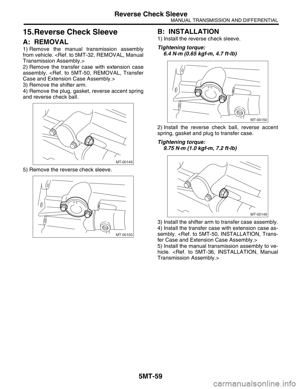
1) Remove the manual transmission assembly
from vehicle.
2) Remove the transfer case with extension case
assembly.
3) Remove the shifter arm.
4) Remove the plug, gasket, reverse accent spring
and reverse check ball.
5) Remove the reverse check sleeve.
B: INSTALLATION
1) Install the reverse check sleeve.
Tightening torque:
6.4 N·m (0.65 kgf-m, 4.7 ft-lb)
2) Install the reverse check ball, reverse accent
spring, gasket and plug to transfer case.
Tightening torque:
9.75 N·m (1.0 kgf-m, 7.2 ft-lb)
3) Install the shifter arm to transfer case assembly.
4) Install the transfer case with extension case as-
sembly.
5) Install the manual transmission assembly to ve-
hicle.
MT-00149
MT-00150
MT-00150
MT-00149
Page 2774 of 2870
5MT-61
MANUAL TRANSMISSION AND DIFFERENTIAL
Reverse Check Sleeve
E: INSPECTION
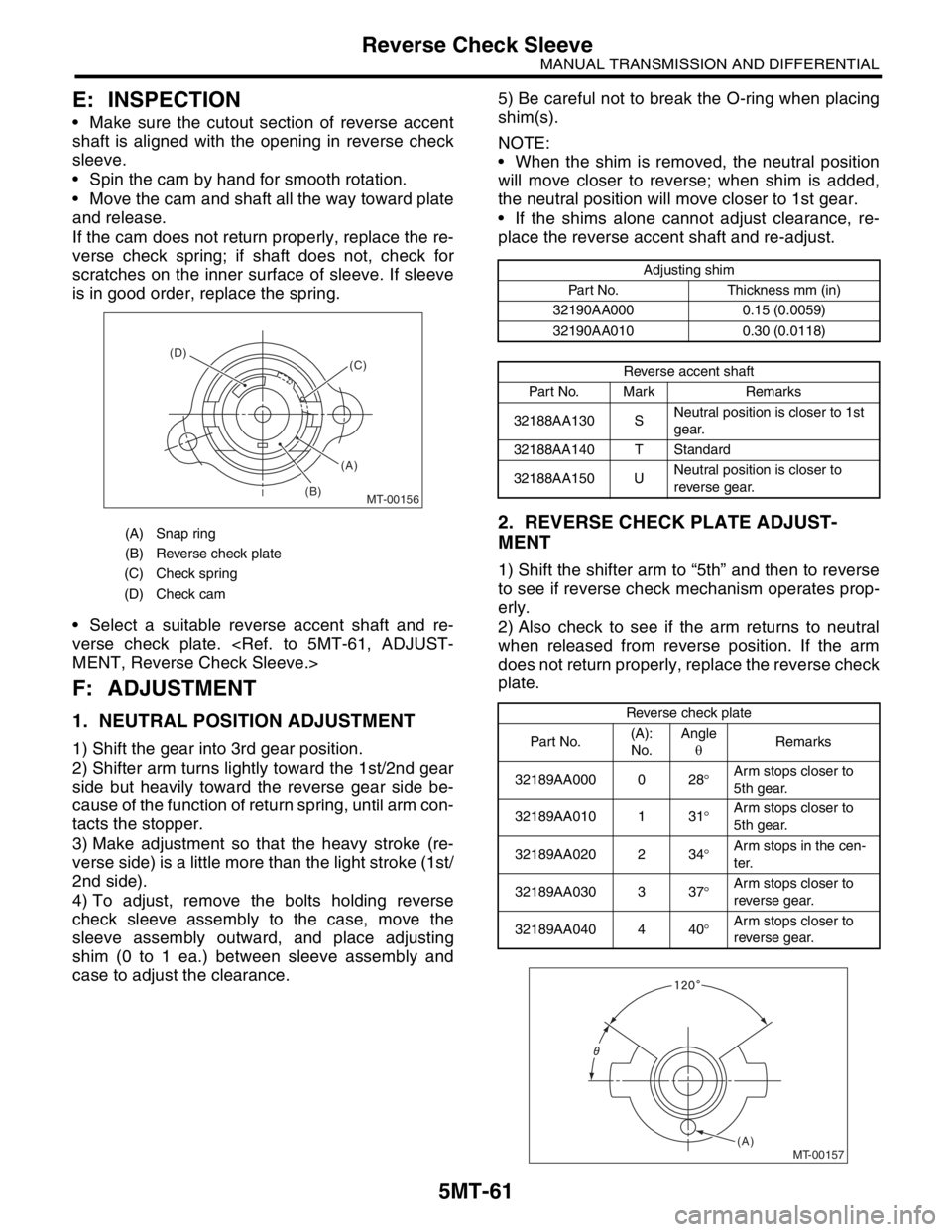
Make sure the cutout section of reverse accent
shaft is aligned with the opening in reverse check
sleeve.
Spin the cam by hand for smooth rotation.
Move the cam and shaft all the way toward plate
and release.
If the cam does not return properly, replace the re-
verse check spring; if shaft does not, check for
scratches on the inner surface of sleeve. If sleeve
is in good order, replace the spring.
Select a suitable reverse accent shaft and re-
verse check plate.
F: ADJUSTMENT
1. NEUTRAL POSITION ADJUSTMENT
1) Shift the gear into 3rd gear position.
2) Shifter arm turns lightly toward the 1st/2nd gear
side but heavily toward the reverse gear side be-
cause of the function of return spring, until arm con-
tacts the stopper.
3) Make adjustment so that the heavy stroke (re-
verse side) is a little more than the light stroke (1st/
2nd side).
4) To adjust, remove the bolts holding reverse
check sleeve assembly to the case, move the
sleeve assembly outward, and place adjusting
shim (0 to 1 ea.) between sleeve assembly and
case to adjust the clearance.5) Be careful not to break the O-ring when placing
shim(s).
NOTE:
When the shim is removed, the neutral position
will move closer to reverse; when shim is added,
the neutral position will move closer to 1st gear.
If the shims alone cannot adjust clearance, re-
place the reverse accent shaft and re-adjust.
2. REVERSE CHECK PLATE ADJUST-
MENT
1) Shift the shifter arm to “5th” and then to reverse
to see if reverse check mechanism operates prop-
erly.
2) Also check to see if the arm returns to neutral
when released from reverse position. If the arm
does not return properly, replace the reverse check
plate.
(A) Snap ring
(B) Reverse check plate
(C) Check spring
(D) Check cam
MT-00156
(A) (D)
(B)(C)
Adjusting shim
Part No. Thickness mm (in)
32190AA000 0.15 (0.0059)
32190AA010 0.30 (0.0118)
Reverse accent shaft
Part No. Mark Remarks
32188AA130 SNeutral position is closer to 1st
gear.
32188AA140 T Standard
32188AA150 UNeutral position is closer to
reverse gear.
Reverse check plate
Par t No.(A):
No.Angle
θRemarks
32189AA000 0 28°Arm stops closer to
5th gear.
32189AA010 1 31°Arm stops closer to
5th gear.
32189AA020 2 34°Arm stops in the cen-
ter.
32189AA030 3 37°Arm stops closer to
reverse gear.
32189AA040 4 40°Arm stops closer to
reverse gear.
MT-00157(A)
Page 2776 of 2870
5MT-63
MANUAL TRANSMISSION AND DIFFERENTIAL
Transmission Case
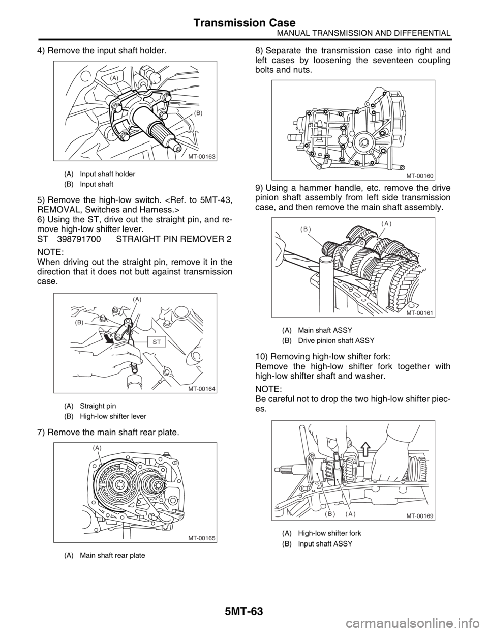
4) Remove the input shaft holder.
5) Remove the high-low switch.
6) Using the ST, drive out the straight pin, and re-
move high-low shifter lever.
ST 398791700 STRAIGHT PIN REMOVER 2
NOTE:
When driving out the straight pin, remove it in the
direction that it does not butt against transmission
case.
7) Remove the main shaft rear plate.8) Separate the transmission case into right and
left cases by loosening the seventeen coupling
bolts and nuts.
9) Using a hammer handle, etc. remove the drive
pinion shaft assembly from left side transmission
case, and then remove the main shaft assembly.
10) Removing high-low shifter fork:
Remove the high-low shifter fork together with
high-low shifter shaft and washer.
NOTE:
Be careful not to drop the two high-low shifter piec-
es.
(A) Input shaft holder
(B) Input shaft
(A) Straight pin
(B) High-low shifter lever
(A) Main shaft rear plate
MT-00163
(A)
(B)
MT-00164
(A)
(B)
ST
MT-00165
(A)
(A) Main shaft ASSY
(B) Drive pinion shaft ASSY
(A) High-low shifter fork
(B) Input shaft ASSY
MT-00160
MT-00161
(A)
(B)
MT-00169(B) (A)