driver SUBARU FORESTER 2004 Service Repair Manual
[x] Cancel search | Manufacturer: SUBARU, Model Year: 2004, Model line: FORESTER, Model: SUBARU FORESTER 2004Pages: 2870, PDF Size: 38.67 MB
Page 1 of 2870
FUJI HEAVY INDUSTRIES LTD. G8080GE7
2004 FORESTER SERVICE MANUAL QUICK REFERENCE INDEX
BODY SECTION
This service manual has been prepared
to provide SUBARU service personnel
with the necessary information and data
for the correct maintenance and repair
of SUBARU vehicles.
This manual includes the procedures
for maintenance, disassembling, reas-
sembling, inspection and adjustment of
components and diagnostics for guid-
ance of experienced mechanics.
Please peruse and utilize this manual
fully to ensure complete repair work for
satisfying our customers by keeping
their vehicle in optimum condition.
When replacement of parts during
repair work is needed, be sure to use
SUBARU genuine parts.
All information, illustration and specifi-
cations contained in this manual are
based on the latest product information
available at the time of publication
approval.HVAC SYSTEM
(HEATER, VENTILATOR AND A/C)AC
HVAC SYSTEM (AUTO A/C)
(DIAGNOSTIC)AC
AIRBAG SYSTEM AB
AIRBAG SYSTEM (DIAGNOSTIC) AB
SEAT BELT SYSTEM SB
LIGHTING SYSTEM LI
WIPER AND WASHER SYSTEM WW
ENTERTAINMENT ET
COMMUNICATION SYSTEM COM
GLASS/WINDOW/MIRROR GW
BODY STRUCTURE BS
INSTRUMENTATION/DRIVER INFO IDI
SEAT SE
SECURITY AND LOCK SL
SUNROOF/T-TOP/CONVERTIBLE TOP
(SUNROOF)SR
EXTERIOR/INTERIOR TRIM EI
EXTERIOR BODY PANEL EB
Page 37 of 2870
AC-35
HVAC SYSTEM (HEATER, VENTILATOR AND A/C)
Control Unit
10.Control Unit
A: REMOVAL
1) Disconnect the ground cable from battery.
2) In case of manual A/C, remove the mode cable
and air-mix cable from links of heater unit.
3) Remove the console front cover.
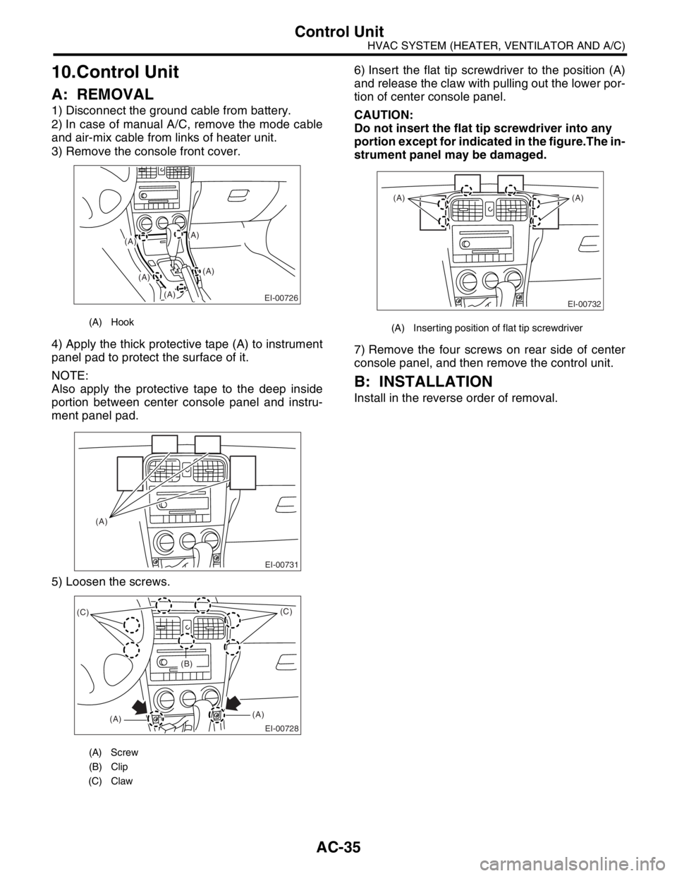
4) Apply the thick protective tape (A) to instrument
panel pad to protect the surface of it.
NOTE:
Also apply the protective tape to the deep inside
portion between center console panel and instru-
ment panel pad.
5) Loosen the screws.6) Insert the flat tip screwdriver to the position (A)
and release the claw with pulling out the lower por-
tion of center console panel.
CAUTION:
Do not insert the flat tip screwdriver into any
portion except for indicated in the figure.The in-
strument panel may be damaged.
7) Remove the four screws on rear side of center
console panel, and then remove the control unit.
B: INSTALLATION
Install in the reverse order of removal.
(A) Hook
(A) Screw
(B) Clip
(C) Claw
(A)
(A)
EI-00726
(A)
(A)
(A)
EI-00731
(A)
EI-00728
(C)
(A)(A)(C)
(B)
(A) Inserting position of flat tip screwdriver
EI-00732
(A) (A)
Page 39 of 2870
AC-37
HVAC SYSTEM (HEATER, VENTILATOR AND A/C)
Condenser
12.Condenser
A: REMOVAL
1) Using the refrigerant recovery system, discharge
refrigerant.
2) Disconnect the ground cable from battery.
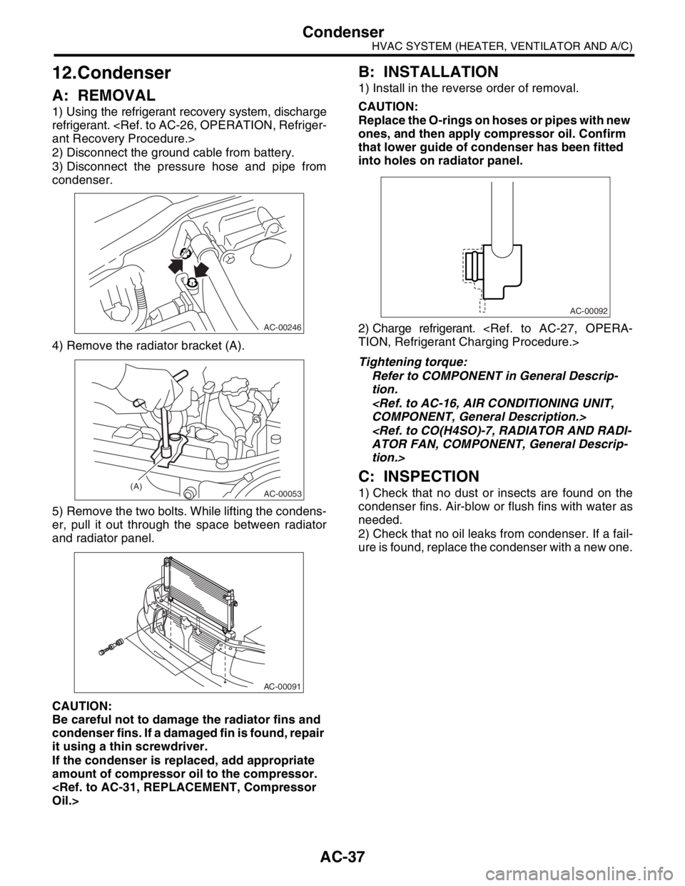
3) Disconnect the pressure hose and pipe from
condenser.
4) Remove the radiator bracket (A).
5) Remove the two bolts. While lifting the condens-
er, pull it out through the space between radiator
and radiator panel.
CAUTION:
Be careful not to damage the radiator fins and
condenser fins. If a damaged fin is found, repair
it using a thin screwdriver.
If the condenser is replaced, add appropriate
amount of compressor oil to the compressor.
B: INSTALLATION
1) Install in the reverse order of removal.
CAUTION:
Replace the O-rings on hoses or pipes with new
ones, and then apply compressor oil. Confirm
that lower guide of condenser has been fitted
into holes on radiator panel.
2) Charge refrigerant.
Tightening torque:
Refer to COMPONENT in General Descrip-
tion.
tion.>
C: INSPECTION
1) Check that no dust or insects are found on the
condenser fins. Air-blow or flush fins with water as
needed.
2) Check that no oil leaks from condenser. If a fail-
ure is found, replace the condenser with a new one.
AC-00246
AC-00053(A)
AC-00091
AC-00092
Page 55 of 2870
FUJI HEAVY INDUSTRIES LTD. G8080GE7
2004 FORESTER SERVICE MANUAL QUICK REFERENCE INDEX
BODY SECTION
This service manual has been prepared
to provide SUBARU service personnel
with the necessary information and data
for the correct maintenance and repair
of SUBARU vehicles.
This manual includes the procedures
for maintenance, disassembling, reas-
sembling, inspection and adjustment of
components and diagnostics for guid-
ance of experienced mechanics.
Please peruse and utilize this manual
fully to ensure complete repair work for
satisfying our customers by keeping
their vehicle in optimum condition.
When replacement of parts during
repair work is needed, be sure to use
SUBARU genuine parts.
All information, illustration and specifi-
cations contained in this manual are
based on the latest product information
available at the time of publication
approval.HVAC SYSTEM
(HEATER, VENTILATOR AND A/C)AC
HVAC SYSTEM (AUTO A/C)
(DIAGNOSTIC)AC
AIRBAG SYSTEM AB
AIRBAG SYSTEM (DIAGNOSTIC) AB
SEAT BELT SYSTEM SB
LIGHTING SYSTEM LI
WIPER AND WASHER SYSTEM WW
ENTERTAINMENT ET
COMMUNICATION SYSTEM COM
GLASS/WINDOW/MIRROR GW
BODY STRUCTURE BS
INSTRUMENTATION/DRIVER INFO IDI
SEAT SE
SECURITY AND LOCK SL
SUNROOF/T-TOP/CONVERTIBLE TOP
(SUNROOF)SR
EXTERIOR/INTERIOR TRIM EI
EXTERIOR BODY PANEL EB
Page 99 of 2870
FUJI HEAVY INDUSTRIES LTD. G8080GE7
2004 FORESTER SERVICE MANUAL QUICK REFERENCE INDEX
BODY SECTION
This service manual has been prepared
to provide SUBARU service personnel
with the necessary information and data
for the correct maintenance and repair
of SUBARU vehicles.
This manual includes the procedures
for maintenance, disassembling, reas-
sembling, inspection and adjustment of
components and diagnostics for guid-
ance of experienced mechanics.
Please peruse and utilize this manual
fully to ensure complete repair work for
satisfying our customers by keeping
their vehicle in optimum condition.
When replacement of parts during
repair work is needed, be sure to use
SUBARU genuine parts.
All information, illustration and specifi-
cations contained in this manual are
based on the latest product information
available at the time of publication
approval.HVAC SYSTEM
(HEATER, VENTILATOR AND A/C)AC
HVAC SYSTEM (AUTO A/C)
(DIAGNOSTIC)AC
AIRBAG SYSTEM AB
AIRBAG SYSTEM (DIAGNOSTIC) AB
SEAT BELT SYSTEM SB
LIGHTING SYSTEM LI
WIPER AND WASHER SYSTEM WW
ENTERTAINMENT ET
COMMUNICATION SYSTEM COM
GLASS/WINDOW/MIRROR GW
BODY STRUCTURE BS
INSTRUMENTATION/DRIVER INFO IDI
SEAT SE
SECURITY AND LOCK SL
SUNROOF/T-TOP/CONVERTIBLE TOP
(SUNROOF)SR
EXTERIOR/INTERIOR TRIM EI
EXTERIOR BODY PANEL EB
Page 101 of 2870

AIRBAG SYSTEM
AB
Page
1. General Description ....................................................................................2
2. Airbag Connector ........................................................................................9
3. Inspection Locations After a Collision .......................................................12
4. Driver’s Airbag Module ..............................................................................14
5. Passenger’s Airbag Module ......................................................................15
6. Side Airbag Module ...................................................................................16
7. Airbag Control Module ..............................................................................18
8. Side Airbag Sensor ...................................................................................19
9. Roll Connector ..........................................................................................20
10. Front Sub Sensor ......................................................................................21
11. Airbag Module Disposal (Deployment Processing On Vehicle) ................22
12. Disposal of Airbag Module (Deploying After Removal from Vehicle) ........26
Page 102 of 2870
AB-2
AIRBAG SYSTEM
General Description
1. General Description
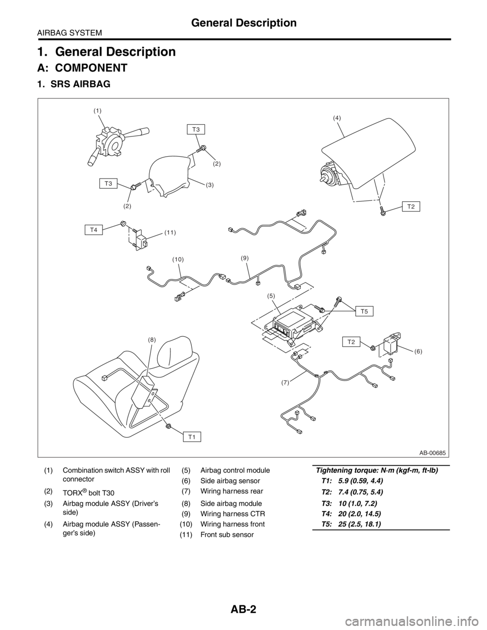
A: COMPONENT
1. SRS AIRBAG
(1) Combination switch ASSY with roll
connector(5) Airbag control moduleTightening torque: N·m (kgf-m, ft-lb)
(6) Side airbag sensorT1: 5.9 (0.59, 4.4)
(2)
TORX
® bolt T30(7) Wiring harness rear
T2: 7.4 (0.75, 5.4)
(3) Airbag module ASSY (Driver’s
side)(8) Side airbag moduleT3: 10 (1.0, 7.2)
(9) Wiring harness CTRT4: 20 (2.0, 14.5)
(4) Airbag module ASSY (Passen-
ger’s side)(10) Wiring harness frontT5: 25 (2.5, 18.1)
(11) Front sub sensor
AB-00685
T3
T2
T5
T3
T4(2)(4)
(3) (1)
(2)
(10)
(11)
(9)
(7)(6) (5)
(8)T2
T1
Page 103 of 2870
AB-3
AIRBAG SYSTEM
General Description
B: CAUTION
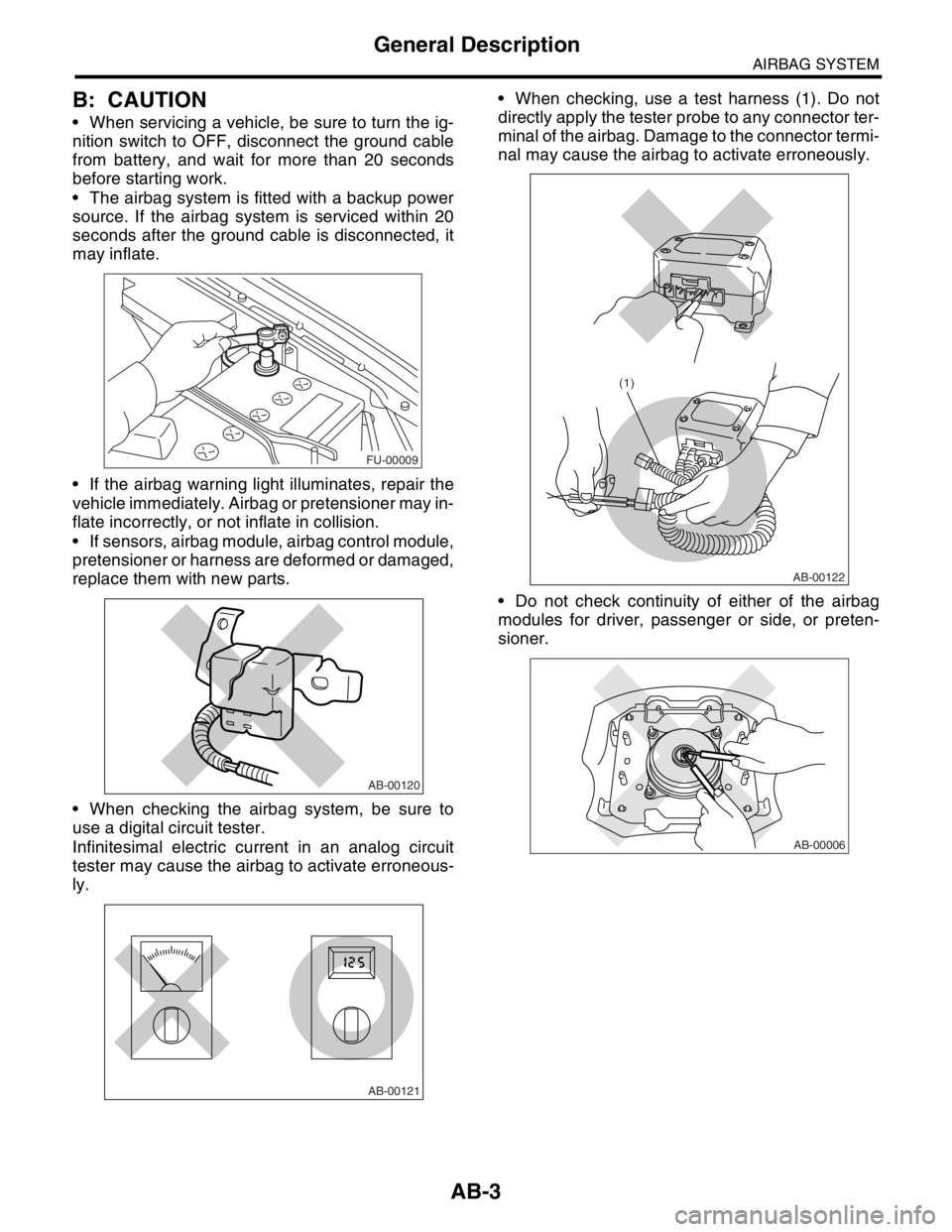
When servicing a vehicle, be sure to turn the ig-
nition switch to OFF, disconnect the ground cable
from battery, and wait for more than 20 seconds
before starting work.
The airbag system is fitted with a backup power
source. If the airbag system is serviced within 20
seconds after the ground cable is disconnected, it
may inflate.
If the airbag warning light illuminates, repair the
vehicle immediately. Airbag or pretensioner may in-
flate incorrectly, or not inflate in collision.
If sensors, airbag module, airbag control module,
pretensioner or harness are deformed or damaged,
replace them with new parts.
When checking the airbag system, be sure to
use a digital circuit tester.
Infinitesimal electric current in an analog circuit
tester may cause the airbag to activate erroneous-
ly. When checking, use a test harness (1). Do not
directly apply the tester probe to any connector ter-
minal of the airbag. Damage to the connector termi-
nal may cause the airbag to activate erroneously.
Do not check continuity of either of the airbag
modules for driver, passenger or side, or preten-
sioner.
FU-00009
AB-00120
AB-00121
AB-00122
(1)
AB-00006
Page 104 of 2870
AB-4
AIRBAG SYSTEM
General Description
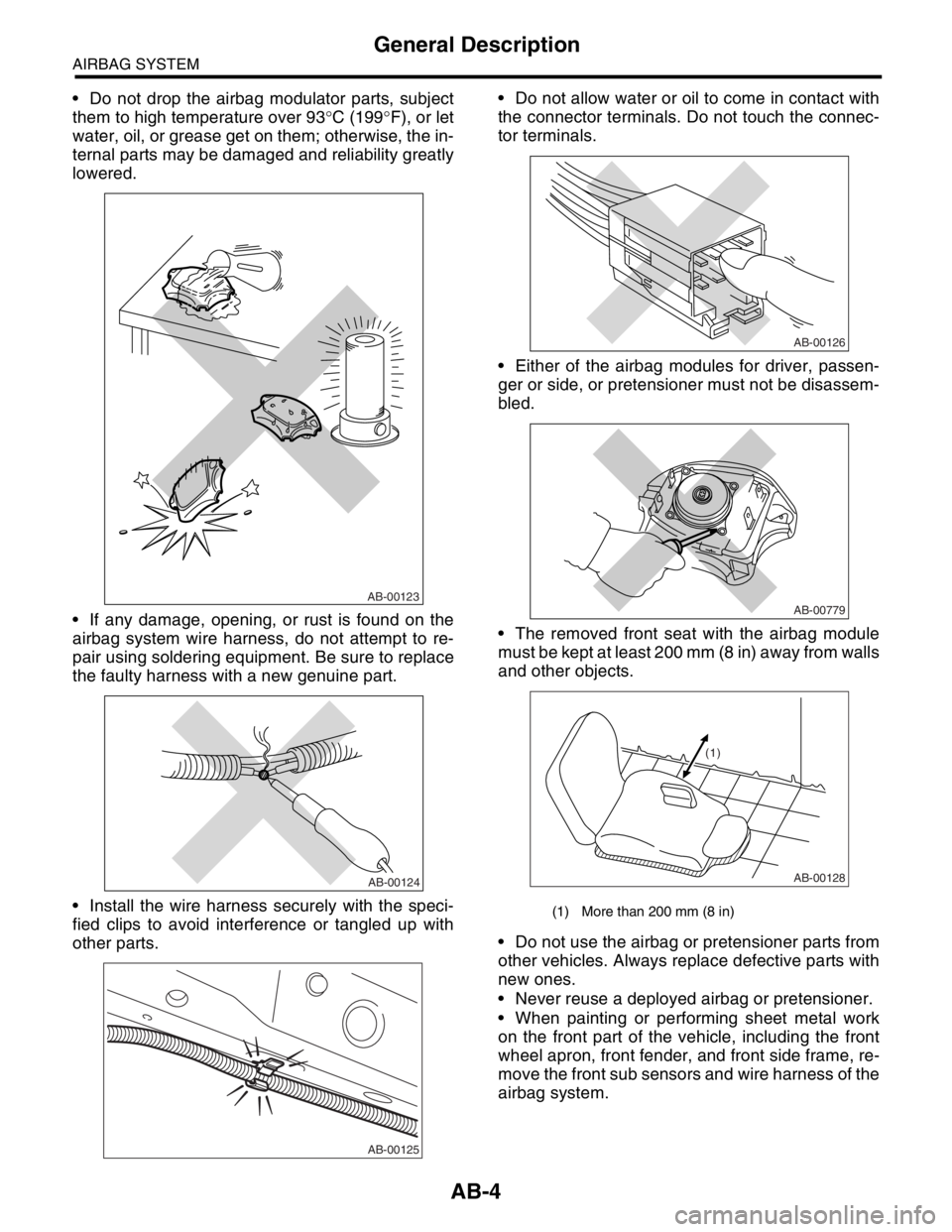
Do not drop the airbag modulator parts, subject
them to high temperature over 93°C (199°F), or let
water, oil, or grease get on them; otherwise, the in-
ternal parts may be damaged and reliability greatly
lowered.
If any damage, opening, or rust is found on the
airbag system wire harness, do not attempt to re-
pair using soldering equipment. Be sure to replace
the faulty harness with a new genuine part.
Install the wire harness securely with the speci-
fied clips to avoid interference or tangled up with
other parts. Do not allow water or oil to come in contact with
the connector terminals. Do not touch the connec-
tor terminals.
Either of the airbag modules for driver, passen-
ger or side, or pretensioner must not be disassem-
bled.
The removed front seat with the airbag module
must be kept at least 200 mm (8 in) away from walls
and other objects.
Do not use the airbag or pretensioner parts from
other vehicles. Always replace defective parts with
new ones.
Never reuse a deployed airbag or pretensioner.
When painting or performing sheet metal work
on the front part of the vehicle, including the front
wheel apron, front fender, and front side frame, re-
move the front sub sensors and wire harness of the
airbag system.
AB-00123
AB-00124
AB-00125
(1) More than 200 mm (8 in)
AB-00126
AB-00779
AB-00128
(1)
Page 106 of 2870
AB-6
AIRBAG SYSTEM
General Description
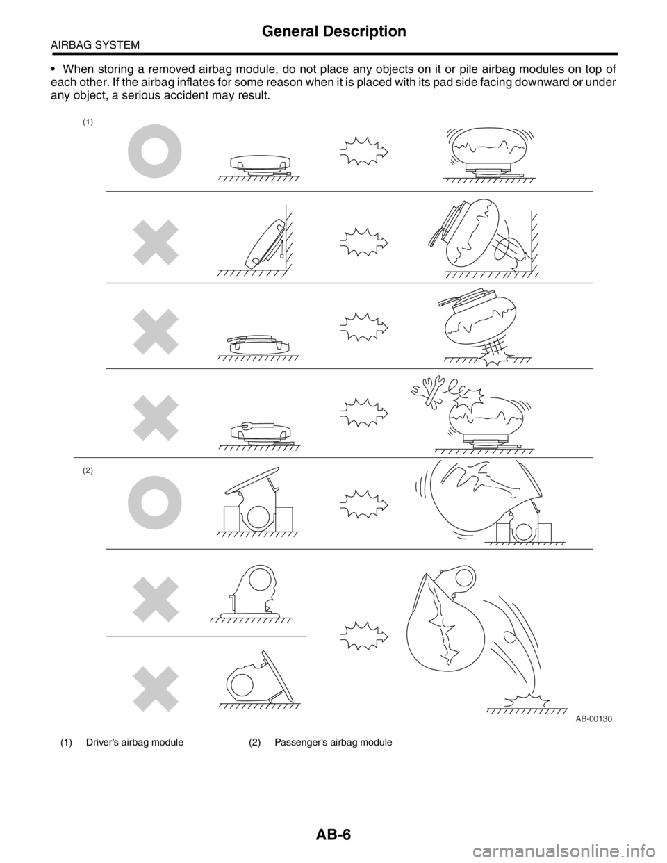
When storing a removed airbag module, do not place any objects on it or pile airbag modules on top of
each other. If the airbag inflates for some reason when it is placed with its pad side facing downward or under
any object, a serious accident may result.
(1) Driver’s airbag module (2) Passenger’s airbag module
AB-00130
(2) (1)