driver SUBARU FORESTER 2004 Service Service Manual
[x] Cancel search | Manufacturer: SUBARU, Model Year: 2004, Model line: FORESTER, Model: SUBARU FORESTER 2004Pages: 2870, PDF Size: 38.67 MB
Page 179 of 2870

AB-47
AIRBAG SYSTEM (DIAGNOSTIC)
Diagnostic Procedure with Diagnostic Trouble Code (DTC)
Step Check Yes No
1 CHECK DRIVERS AIRBAG MODULE.
1) Turn the ignition switch to OFF, disconnect
the battery ground cable, and wait more than
20 seconds.
2) Remove the driver’s airbag module.
3) Connect the connector (1N) in test harness
N to connector (AB2).
4) Connect the airbag resistor to connector
(2N) in test harness N.
5) Connect the battery ground cable and turn
the ignition switch to ON.Is the airbag warning light
turned on normally?Replace the
driver’s airbag
module.
Airbag Module.>Go to step 2.
2 CHECK ROLL CONNECTOR.
1) Turn the ignition switch to OFF, disconnect
the battery ground cable, and wait more than
20 second.
2) Disconnect the test harness N from the
connector (AB2).
3) Remove the instrument panel lower cover,
disconnect the connector (AB26) from (AB21)
and connect the connector (1F) in test harness
F to connector (AB21).
4) Connect the airbag resistor to connector
(3F) in test harness F.
5) Connect the battery ground cable and turn
the ignition switch to ON.Is the airbag warning light turn
on normally?Replace the roll
connector.
nector.>Go to step 3.
3 CHECK AIRBAG MAIN HARNESS.
1) Turn the ignition switch to OFF, disconnect
the ground cable, and wait more than 20 sec-
onds.
2) Disconnect the airbag resistor from the
connector (3F) in test harness F.
3) Remove the glove box, and disconnect con-
nectors (AB4) and passenger’s airbag module
(AB27).
4) Disconnect the connector (AB3) from the
airbag control module, and connect the con-
nector (1R) in test harness R.
5) Measure the resistance between connector
(2R) in test harness R and the connector (3F)
in test harness F.
Connector & terminal
(2R) No. 2 — (3F) No. 4:
(2R) No. 4 — (3F) No. 3: Is the resistance less than 10
Ω?Go to step 4.Replace the airbag
main harness with
body harness.
4 CHECK AIRBAG MAIN HARNESS.
Measure the resistance of the connector (2R)
in test harness R.
Connector & terminal
(2R) No. 2 — (2R) No. 4:
(2R) No. 4 — Chassis ground:
(2R) No. 2 — Chassis ground:Is the resistance more than 1
MΩ?Replace the airbag
control module.
Module.>Replace the airbag
main harness with
body harness.
Page 180 of 2870
AB-48
AIRBAG SYSTEM (DIAGNOSTIC)
Diagnostic Procedure with Diagnostic Trouble Code (DTC)
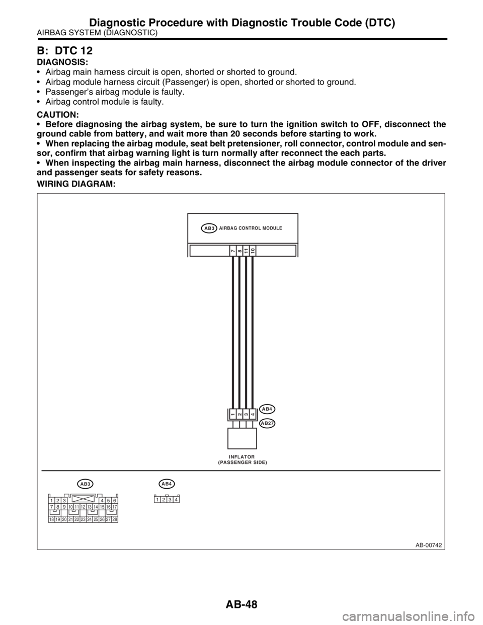
B: DTC 12
DIAGNOSIS:
Airbag main harness circuit is open, shorted or shorted to ground.
Airbag module harness circuit (Passenger) is open, shorted or shorted to ground.
Passenger’s airbag module is faulty.
Airbag control module is faulty.
CAUTION:
Before diagnosing the airbag system, be sure to turn the ignition switch to OFF, disconnect the
ground cable from battery, and wait more than 20 seconds before starting to work.
When replacing the airbag module, seat belt pretensioner, roll connector, control module and sen-
sor, confirm that airbag warning light is turn normally after reconnect the each parts.
When inspecting the airbag main harness, disconnect the airbag module connector of the driver
and passenger seats for safety reasons.
WIRING DIAGRAM:
AB-00742
AB3 INFLATOR
(PASSENGER SIDE)
AB4
AB4
AB27
11
10 3
47
8
1
2
AIRBAG CONTROL MODULEAB3
12341234567891011121314151617
1819202122232425262728
Page 182 of 2870
AB-50
AIRBAG SYSTEM (DIAGNOSTIC)
Diagnostic Procedure with Diagnostic Trouble Code (DTC)
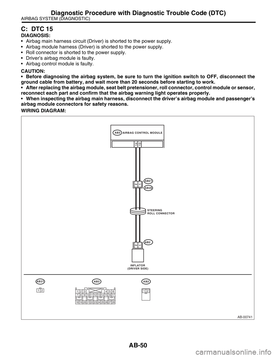
C: DTC 15
DIAGNOSIS:
Airbag main harness circuit (Driver) is shorted to the power supply.
Airbag module harness (Driver) is shorted to the power supply.
Roll connector is shorted to the power supply.
Driver’s airbag module is faulty.
Airbag control module is faulty.
CAUTION:
Before diagnosing the airbag system, be sure to turn the ignition switch to OFF, disconnect the
ground cable from battery, and wait more than 20 seconds before starting to work.
After replacing the airbag module, seat belt pretensioner, roll connector, control module or sensor,
reconnect each part and confirm that the airbag warning light operates properly.
When inspecting the airbag main harness, disconnect the driver’s airbag module and passenger’s
airbag module connectors for safety reasons.
WIRING DIAGRAM:
AB-00741
AB3
AB21
AB26
AB222
11
14
13
AB21AB3AB2
1212
AIRBAG CONTROL MODULE
STEERING
ROLL CONNECTOR
INFLATOR
(DRIVER SIDE)
1234567891011121314151617
1819202122232425262728
Page 183 of 2870

AB-51
AIRBAG SYSTEM (DIAGNOSTIC)
Diagnostic Procedure with Diagnostic Trouble Code (DTC)
Step Check Yes No
1 CHECK DRIVERS AIRBAG MODULE.
1) Turn the ignition switch to OFF, disconnect
the battery ground cable, and wait more than
20 seconds.
2) Remove the driver’s airbag module.
3) Connect the connector (AB2) to connector
(1N) in test harness N.
4) Connect the airbag resistor to connector
(2N) in test harness N.
5) Connect the battery ground cable and turn
the ignition switch to ON.Is the airbag warning light
turned on normally?Replace the
driver’s airbag
module.
Airbag Module.>Go to step 2.
2 CHECK ROLL CONNECTOR.
1) Turn the ignition switch to OFF, disconnect
the battery ground cable, and wait more than
20 seconds.
2) Disconnect the test harness N from the
connector (AB2).
3) Remove the instrument panel lower cover
and disconnect the connector (AB21) from
(AB26).
4) Connect the connector (1F) in test harness
F to connector (AB21).
5) Connect the airbag resistor to connector
(3F) in test harness F.
6) Connect the battery ground cable and turn
the ignition switch to ON.Is the airbag warning light
turned on normally?Replace the roll
connector.
nector.>Go to step 3.
3 CHECK AIRBAG MAIN HARNESS.
1) Turn the ignition switch to OFF, disconnect
the battery ground cable, and wait more than
20 seconds.
2) Disconnect the airbag resistor from the
connector (3F) in test harness F.
3) Remove the glove box, and disconnect the
connectors (AB4) and passenger’s airbag
module (AB27).
4) Disconnect the connector (AB3) from the
airbag control module, and connect the con-
nector (1R) in test harness R.
5) Connect the battery ground cable and turn
the ignition switch to ON. (engine OFF)
6) Measure the voltage between connector
(2R) in test harness R and the chassis ground.
Connector & terminal
(2R) No. 2 (+) — Chassis ground (
−):
(2R) No. 4 (+) — Chassis ground (
−): Is the voltage less than 1 V? Replace the airbag
control module.
Module.>Replace the airbag
main harness with
body harness.
Page 184 of 2870

AB-52
AIRBAG SYSTEM (DIAGNOSTIC)
Diagnostic Procedure with Diagnostic Trouble Code (DTC)
D: DTC 16
DIAGNOSIS:
Airbag main harness circuit (Passenger) is shorted to the power supply.
Airbag module harness (Passenger) is shorted to the power supply.
Passenger’s airbag module is faulty.
Airbag control module is faulty.
CAUTION:
Before diagnosing the airbag system, be sure to turn the ignition switch to OFF, disconnect the
ground cable from battery, and wait more than 20 seconds before starting to work.
After replacing the airbag module, seat belt pretensioner, roll connector, control module or sensor,
reconnect each part and confirm that the airbag warning light operates properly.
When inspecting the airbag main harness, disconnect the airbag module connector of the driver
and passenger seats for safety reasons.
WIRING DIAGRAM:
AB-00742
AB3 INFLATOR
(PASSENGER SIDE)
AB4
AB4
AB27
11
10 3
47
8
1
2
AIRBAG CONTROL MODULEAB3
12341234567891011121314151617
1819202122232425262728
Page 187 of 2870
AB-55
AIRBAG SYSTEM (DIAGNOSTIC)
Diagnostic Procedure with Diagnostic Trouble Code (DTC)
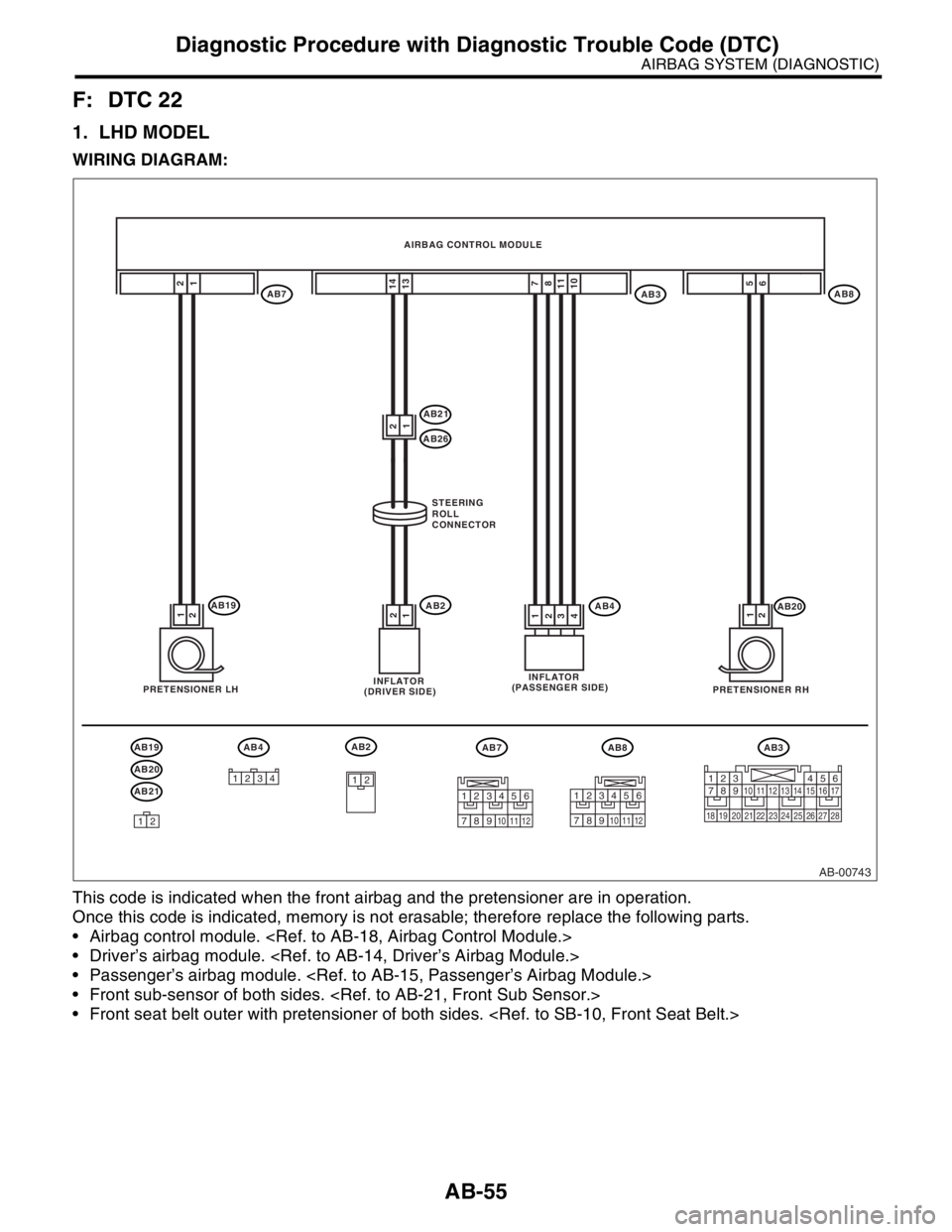
F: DTC 22
1. LHD MODEL
WIRING DIAGRAM:
This code is indicated when the front airbag and the pretensioner are in operation.
Once this code is indicated, memory is not erasable; therefore replace the following parts.
Airbag control module.
Driver’s airbag module.
Passenger’s airbag module.
Front sub-sensor of both sides.
Front seat belt outer with pretensioner of both sides.
AB-00743
AB3AB4
1234
AB3AB8AB7
AB20
6
1
2
52
1
AB4AB193
41
21
2
14
137
811
10
AB21
AB26
AB222
1
1
AB20
AB19
AB21
AB2
12
12
AB7AB8 AIRBAG CONTROL MODULE
STEERING
ROLL
CONNECTOR
PRETENSIONER LHINFLATOR
(DRIVER SIDE)INFLATOR
(PASSENGER SIDE)
PRETENSIONER RH
1234567891011121314151617
1819202122232425262728
123456
789101112
123456
789101112
Page 188 of 2870
AB-56
AIRBAG SYSTEM (DIAGNOSTIC)
Diagnostic Procedure with Diagnostic Trouble Code (DTC)
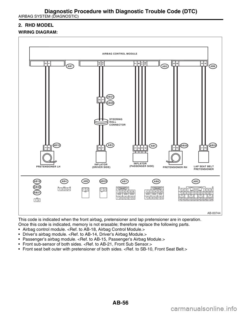
2. RHD MODEL
WIRING DIAGRAM:
This code is indicated when the front airbag, pretensioner and lap pretensioner are in operation.
Once this code is indicated, memory is not erasable; therefore replace the following parts.
Airbag control module.
Driver’s airbag module.
Passenger’s airbag module.
Front sub-sensor of both sides.
Front seat belt outer with pretensioner of both sides.
AB-00744
AB3AB4
1234
AB3AB8AB7
AB20
6
1
2
52
1
AB4AB193
41
21
2
14
137
811
10
AB21
AB26
AB222
1
1
AB20
AB19
AB21
AB2
12
12
AB7AB8 AIRBAG CONTROL MODULE
STEERING
ROLL
CONNECTOR
PRETENSIONER LHINFLATOR
(DRIVER SIDE)INFLATOR
(PASSENGER SIDE)
PRETENSIONER RH
AB25
12
AB251
2
LAP SEAT BELT
PRETENSIONER
4 3
123456
789101112
123456
789101112
1234567891011121314151617
1819202122232425262728
Page 190 of 2870
AB-58
AIRBAG SYSTEM (DIAGNOSTIC)
Diagnostic Procedure with Diagnostic Trouble Code (DTC)
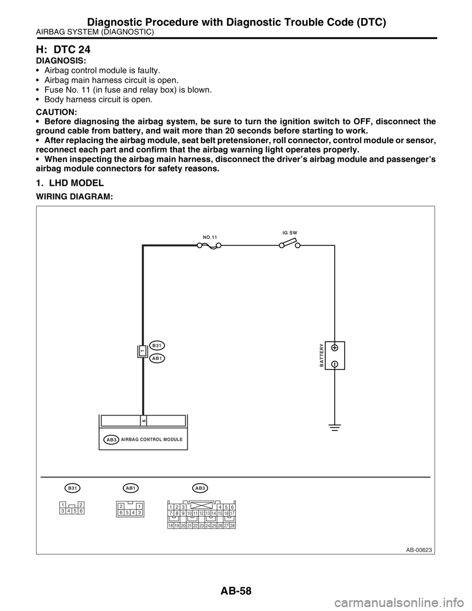
H: DTC 24
DIAGNOSIS:
Airbag control module is faulty.
Airbag main harness circuit is open.
Fuse No. 11 (in fuse and relay box) is blown.
Body harness circuit is open.
CAUTION:
Before diagnosing the airbag system, be sure to turn the ignition switch to OFF, disconnect the
ground cable from battery, and wait more than 20 seconds before starting to work.
After replacing the airbag module, seat belt pretensioner, roll connector, control module or sensor,
reconnect each part and confirm that the airbag warning light operates properly.
When inspecting the airbag main harness, disconnect the driver’s airbag module and passenger’s
airbag module connectors for safety reasons.
1. LHD MODEL
WIRING DIAGRAM:
AB-00623
AB3
AIRBAG CONTROL MODULEAB3
B31
AB1
AB1
1
6
BATTERY
IG SW
NO.11
B31
12
34561
23 45 61234567891011121314151617
1819202122232425262728
Page 194 of 2870
AB-62
AIRBAG SYSTEM (DIAGNOSTIC)
Diagnostic Procedure with Diagnostic Trouble Code (DTC)
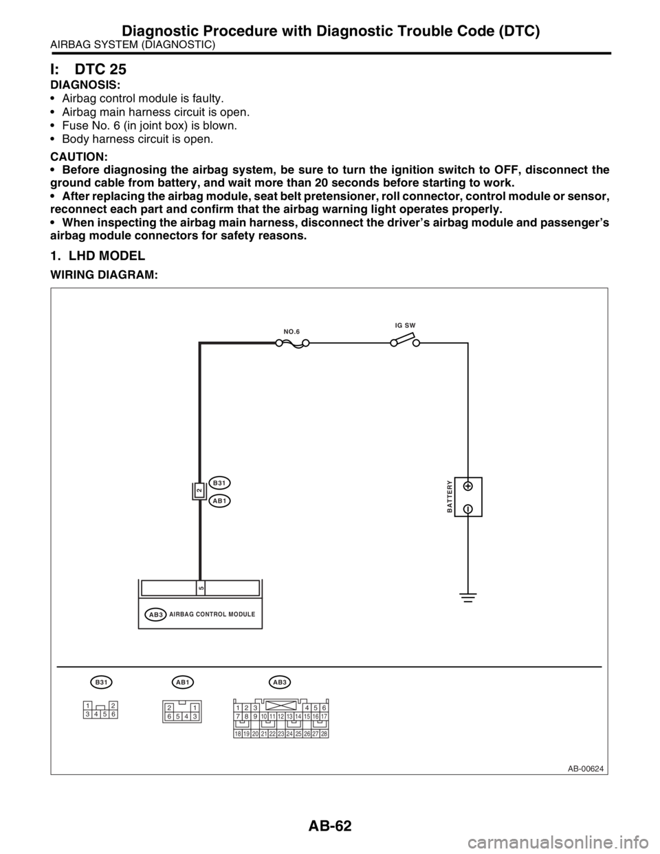
I: DTC 25
DIAGNOSIS:
Airbag control module is faulty.
Airbag main harness circuit is open.
Fuse No. 6 (in joint box) is blown.
Body harness circuit is open.
CAUTION:
Before diagnosing the airbag system, be sure to turn the ignition switch to OFF, disconnect the
ground cable from battery, and wait more than 20 seconds before starting to work.
After replacing the airbag module, seat belt pretensioner, roll connector, control module or sensor,
reconnect each part and confirm that the airbag warning light operates properly.
When inspecting the airbag main harness, disconnect the driver’s airbag module and passenger’s
airbag module connectors for safety reasons.
1. LHD MODEL
WIRING DIAGRAM:
AB-00624
AB3
AIRBAG CONTROL MODULEAB3
B31
AB1
AB1
2
5
BATTERY
IG SW
NO.6
B31
12
34561
23 45 61234567891011121314151617
1819202122232425262728
Page 198 of 2870
AB-66
AIRBAG SYSTEM (DIAGNOSTIC)
Diagnostic Procedure with Diagnostic Trouble Code (DTC)
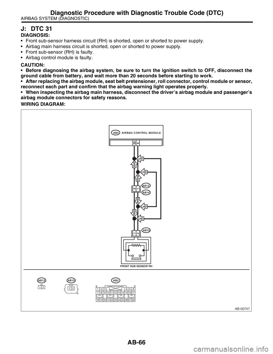
J: DTC 31
DIAGNOSIS:
Front sub-sensor harness circuit (RH) is shorted, open or shorted to power supply.
Airbag main harness circuit is shorted, open or shorted to power supply.
Front sub-sensor (RH) is faulty.
Airbag control module is faulty.
CAUTION:
Before diagnosing the airbag system, be sure to turn the ignition switch to OFF, disconnect the
ground cable from battery, and wait more than 20 seconds before starting to work.
After replacing the airbag module, seat belt pretensioner, roll connector, control module or sensor,
reconnect each part and confirm that the airbag warning light operates properly.
When inspecting the airbag main harness, disconnect the driver’s airbag module and passenger’s
airbag module connectors for safety reasons.
WIRING DIAGRAM:
AB-00747
AB3
AB13
AB14
AB15
AB3
LHD
RHD
LHD
RHD
LHD
FRONT SUB SENSOR RH
209
21
RHD
LHDRHD
AB13AB15
1212
AIRBAG CONTROL MODULE
1
2
1234567891011121314151617
1819202122232425262728