oxygen SUBARU FORESTER 2004 Service Repair Manual
[x] Cancel search | Manufacturer: SUBARU, Model Year: 2004, Model line: FORESTER, Model: SUBARU FORESTER 2004Pages: 2870, PDF Size: 38.67 MB
Page 720 of 2870
RM-5
RECOMMENDED MATERIAL
Recommended Materials
4. FLUID
Use the fluids specified in the table below. Do not mix two different kinds or makes of fluid.
5. COOLANT
Use genuine coolant to protect the engine.
6. REFRIGERANT
Standard air conditioners on Subaru vehicles use HFC134a refrigerant. Do not mix it with other refrigerants.
Also, do not use any air compressor oil except for ZXL200PG.
7. GREASE
Use the grease and supplementary lubricants shown in the table below.
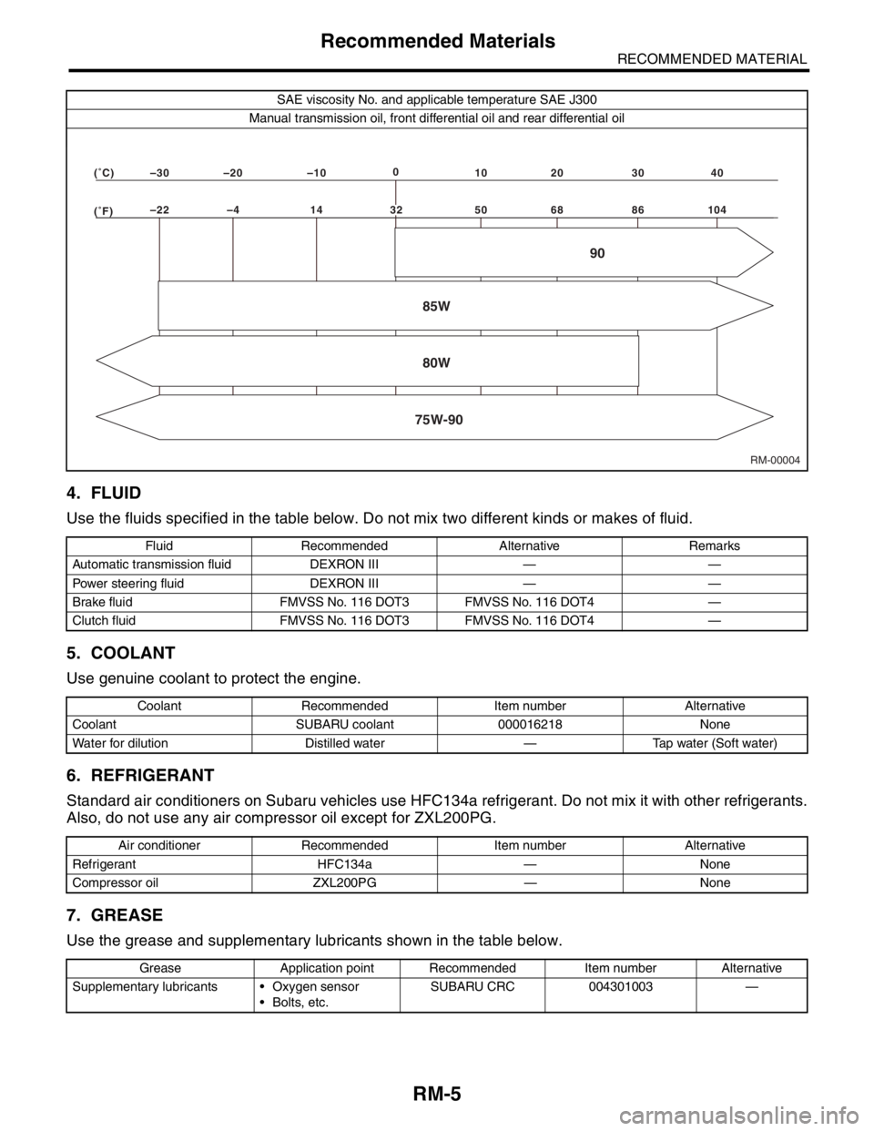
SAE viscosity No. and applicable temperature SAE J300
Manual transmission oil, front differential oil and rear differential oil
Fluid Recommended Alternative Remarks
Automatic transmission fluid DEXRON III — —
Power steering fluid DEXRON III — —
Brake fluid FMVSS No. 116 DOT3 FMVSS No. 116 DOT4 —
Clutch fluid FMVSS No. 116 DOT3 FMVSS No. 116 DOT4 —
Coolant Recommended Item number Alternative
Coolant SUBARU coolant 000016218 None
Water for dilution Distilled water — Tap water (Soft water)
Air conditioner Recommended Item number Alternative
Refrigerant HFC134a — None
Compressor oil ZXL200PG — None
Grease Application point Recommended Item number Alternative
Supplementary lubricants Oxygen sensor
Bolts, etc.SUBARU CRC 004301003 —
RM-00004 (�F)–22 –4 14 50 68 86 104 (�C)–30 –20 –100
10 20 30 40
85W
75W-9080W90
32
Page 783 of 2870

FUEL INJECTION (FUEL SYSTEM)
FU(H4SO)
Page
1. General Description ....................................................................................2
2. Throttle Body .............................................................................................13
3. Intake Manifold ..........................................................................................14
4. Engine Coolant Temperature Sensor........................................................25
5. Crankshaft Position Sensor.......................................................................26
6. Camshaft Position Sensor.........................................................................27
7. Knock Sensor ............................................................................................28
8. Throttle Position Sensor ............................................................................29
9. Manifold Absolute Pressure Sensor ..........................................................31
10. Intake Air Temperature Sensor .................................................................32
11. Idle Air Control Solenoid Valve .................................................................33
12. EGR Valve ................................................................................................34
13. Fuel Injector ..............................................................................................35
14. Front Oxygen (A/F) Sensor .......................................................................40
15. Rear Oxygen Sensor.................................................................................42
16. Engine Control Module (ECM) ..................................................................44
17. Main Relay ................................................................................................45
18. Fuel Pump Relay.......................................................................................46
19. Fuel ...........................................................................................................47
20. Fuel Tank ..................................................................................................48
21. Fuel Filler Pipe ..........................................................................................51
22. Fuel Pump .................................................................................................55
23. Fuel Level Sensor .....................................................................................57
24. Fuel Sub Level Sensor ..............................................................................58
25. Fuel Filter ..................................................................................................60
26. Fuel Cut Valve...........................................................................................61
27. Fuel Damper Valve ...................................................................................62
28. Fuel Delivery, Return and Evaporation Lines............................................63
29. Fuel System Trouble in General ...............................................................66
Page 822 of 2870
FU(H4SO)-40
FUEL INJECTION (FUEL SYSTEM)
Front Oxygen (A/F) Sensor
14.Front Oxygen (A/F) Sensor
A: REMOVAL
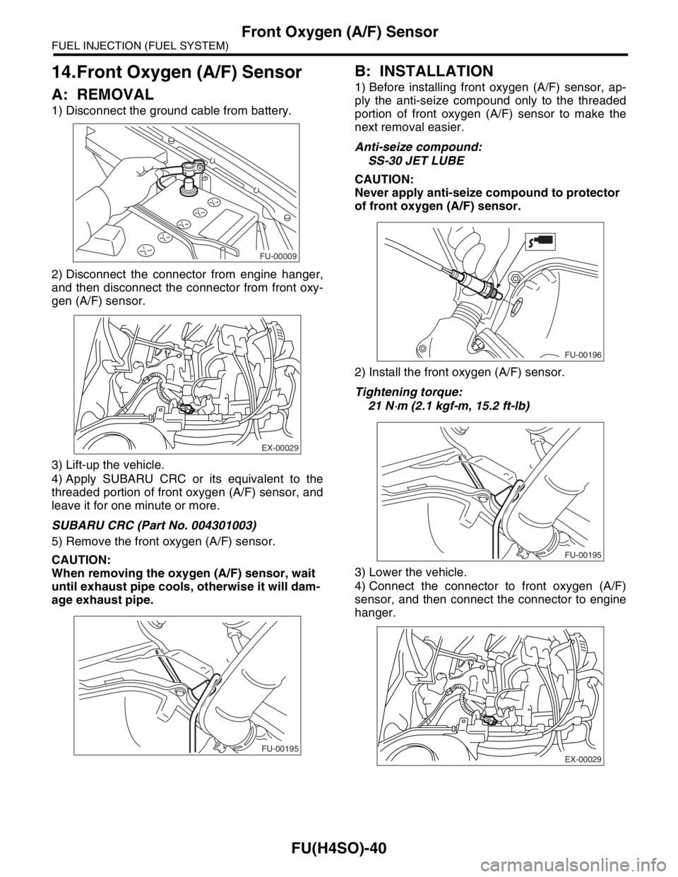
1) Disconnect the ground cable from battery.
2) Disconnect the connector from engine hanger,
and then disconnect the connector from front oxy-
gen (A/F) sensor.
3) Lift-up the vehicle.
4) Apply SUBARU CRC or its equivalent to the
threaded portion of front oxygen (A/F) sensor, and
leave it for one minute or more.
SUBARU CRC (Part No. 004301003)
5) Remove the front oxygen (A/F) sensor.
CAUTION:
When removing the oxygen (A/F) sensor, wait
until exhaust pipe cools, otherwise it will dam-
age exhaust pipe.
B: INSTALLATION
1) Before installing front oxygen (A/F) sensor, ap-
ply the anti-seize compound only to the threaded
portion of front oxygen (A/F) sensor to make the
next removal easier.
Anti-seize compound:
SS-30 JET LUBE
CAUTION:
Never apply anti-seize compound to protector
of front oxygen (A/F) sensor.
2) Install the front oxygen (A/F) sensor.
Tightening torque:
21 N
⋅m (2.1 kgf-m, 15.2 ft-lb)
3) Lower the vehicle.
4) Connect the connector to front oxygen (A/F)
sensor, and then connect the connector to engine
hanger.
FU-00009
EX-00029
FU-00195
FU-00196
FU-00195
EX-00029
Page 823 of 2870
FU(H4SO)-41
FUEL INJECTION (FUEL SYSTEM)
Front Oxygen (A/F) Sensor
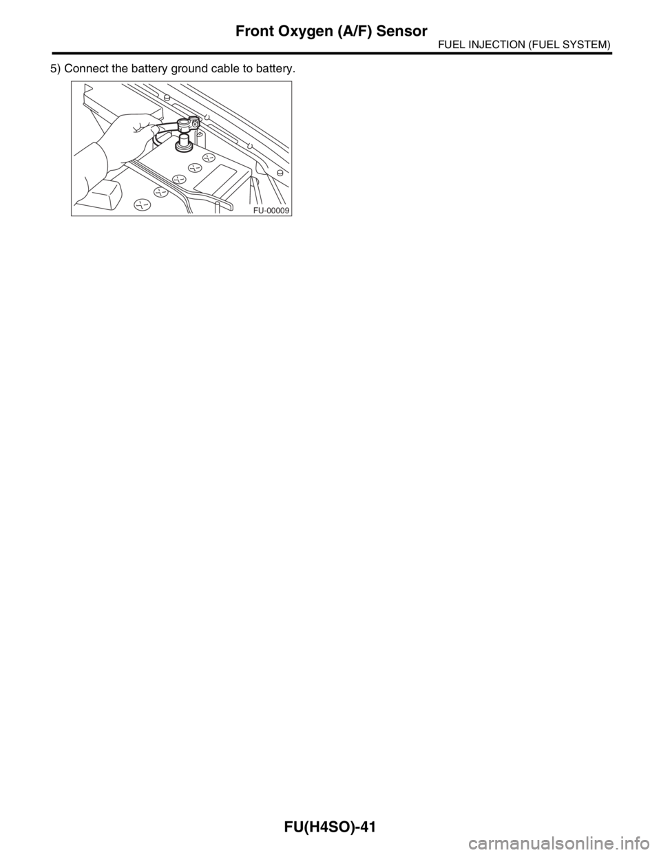
5) Connect the battery ground cable to battery.
FU-00009
Page 824 of 2870
FU(H4SO)-42
FUEL INJECTION (FUEL SYSTEM)
Rear Oxygen Sensor
15.Rear Oxygen Sensor
A: REMOVAL
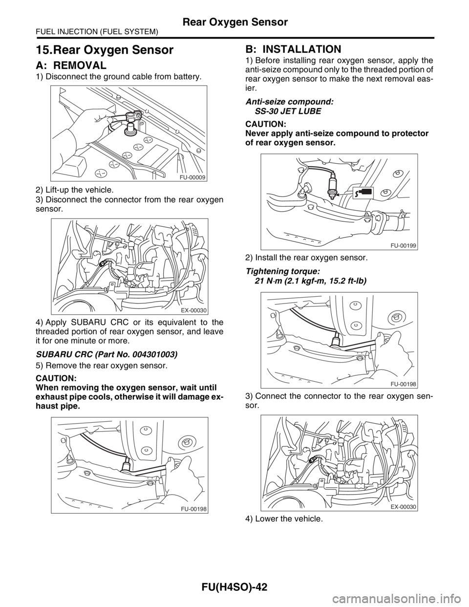
1) Disconnect the ground cable from battery.
2) Lift-up the vehicle.
3) Disconnect the connector from the rear oxygen
sensor.
4) Apply SUBARU CRC or its equivalent to the
threaded portion of rear oxygen sensor, and leave
it for one minute or more.
SUBARU CRC (Part No. 004301003)
5) Remove the rear oxygen sensor.
CAUTION:
When removing the oxygen sensor, wait until
exhaust pipe cools, otherwise it will damage ex-
haust pipe.
B: INSTALLATION
1) Before installing rear oxygen sensor, apply the
anti-seize compound only to the threaded portion of
rear oxygen sensor to make the next removal eas-
ier.
Anti-seize compound:
SS-30 JET LUBE
CAUTION:
Never apply anti-seize compound to protector
of rear oxygen sensor.
2) Install the rear oxygen sensor.
Tightening torque:
21 N
⋅m (2.1 kgf-m, 15.2 ft-lb)
3) Connect the connector to the rear oxygen sen-
sor.
4) Lower the vehicle.
FU-00009
EX-00030
FU-00198
FU-00199
FU-00198
EX-00030
Page 825 of 2870
FU(H4SO)-43
FUEL INJECTION (FUEL SYSTEM)
Rear Oxygen Sensor
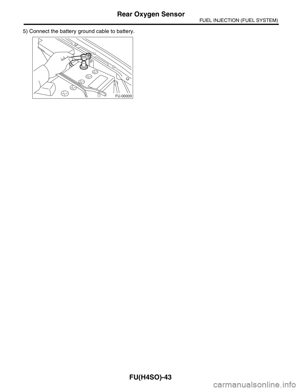
5) Connect the battery ground cable to battery.
FU-00009
Page 852 of 2870
EC(H4SO)-3
EMISSION CONTROL (AUX. EMISSION CONTROL DEVICE)
Front Catalytic Converter
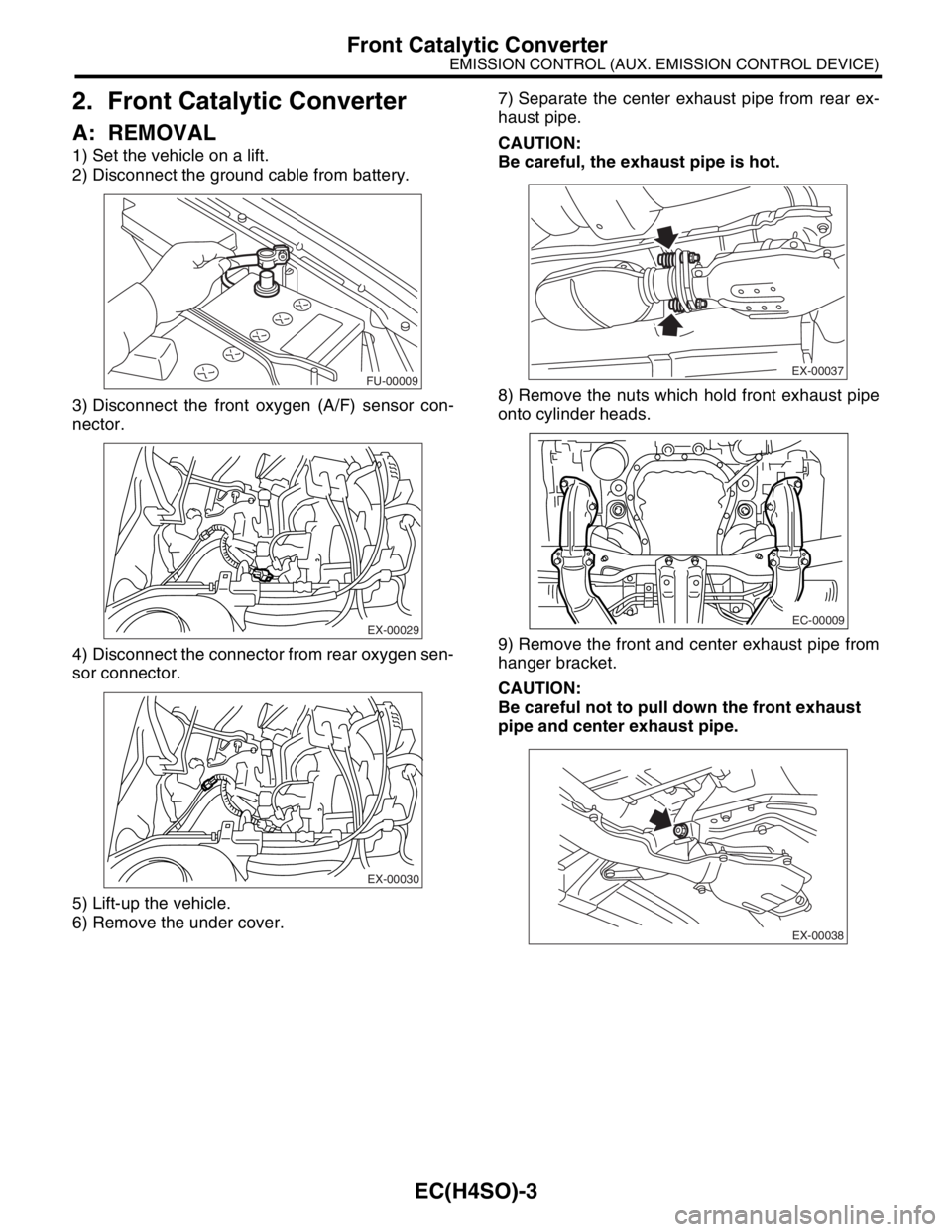
2. Front Catalytic Converter
A: REMOVAL
1) Set the vehicle on a lift.
2) Disconnect the ground cable from battery.
3) Disconnect the front oxygen (A/F) sensor con-
nector.
4) Disconnect the connector from rear oxygen sen-
sor connector.
5) Lift-up the vehicle.
6) Remove the under cover.7) Separate the center exhaust pipe from rear ex-
haust pipe.
CAUTION:
Be careful, the exhaust pipe is hot.
8) Remove the nuts which hold front exhaust pipe
onto cylinder heads.
9) Remove the front and center exhaust pipe from
hanger bracket.
CAUTION:
Be careful not to pull down the front exhaust
pipe and center exhaust pipe.
FU-00009
EX-00029
EX-00030
EX-00037
EC-00009
EX-00038
Page 854 of 2870
EC(H4SO)-5
EMISSION CONTROL (AUX. EMISSION CONTROL DEVICE)
Front Catalytic Converter
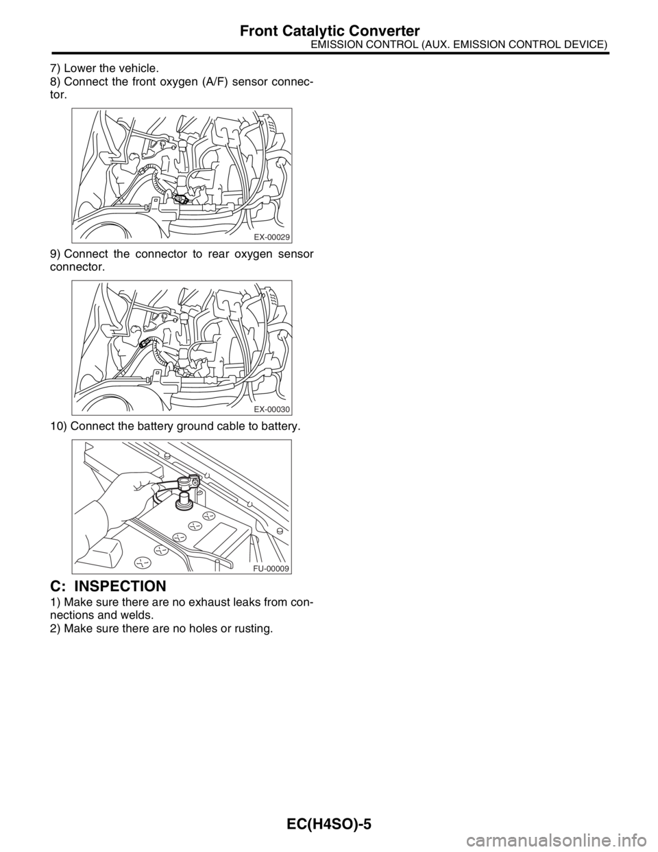
7) Lower the vehicle.
8) Connect the front oxygen (A/F) sensor connec-
tor.
9) Connect the connector to rear oxygen sensor
connector.
10) Connect the battery ground cable to battery.
C: INSPECTION
1) Make sure there are no exhaust leaks from con-
nections and welds.
2) Make sure there are no holes or rusting.
EX-00029
EX-00030
FU-00009
Page 903 of 2870
ME(H4SO)-34
MECHANICAL
Engine Assembly
9. Engine Assembly
A: REMOVAL
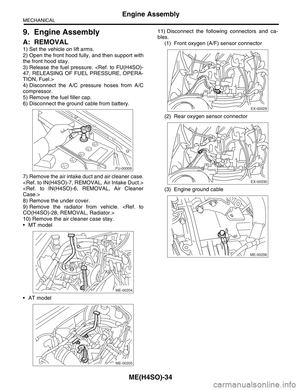
1) Set the vehicle on lift arms.
2) Open the front hood fully, and then support with
the front hood stay.
3) Release the fuel pressure.
TION, Fuel.>
4) Disconnect the A/C pressure hoses from A/C
compressor.
5) Remove the fuel filler cap.
6) Disconnect the ground cable from battery.
7) Remove the air intake duct and air cleaner case.
8) Remove the under cover.
9) Remove the radiator from vehicle.
10) Remove the air cleaner case stay.
MT model
AT model11) Disconnect the following connectors and ca-
bles.
(1) Front oxygen (A/F) sensor connector
(2) Rear oxygen sensor connector
(3) Engine ground cable
FU-00009
ME-00204
ME-00205
EX-00029
EX-00030
ME-00206
Page 971 of 2870

EX(H4SO)-3
EXHAUST
General Description
(1) Front exhaust pipe upper cover
CTR(14) Muffler (28) Rear catalytic converter upper
cover
(15) Cushion rubber
(2) Front exhaust pipe lower cover
CTR(16) Rear exhaust pipe (29) Rear catalytic converter lower
cover
(17) Clamp
(3) Clamp (18) Center exhaust pipe upper cover (30) Rear catalytic converter
(4) Front exhaust pipe upper cover LH (19) Center exhaust pipe lower cover (31) Gasket
(5) Front exhaust pipe lower cover LH (20) Protector
(6) Front exhaust pipe (21) GasketTightening torque: N
⋅m (kgf-m, ft-lb)
(7) Front exhaust pipe lower cover RH (22) Front oxygen (A/F) sensorT1: 8 (0.8, 5.8)
(8) Front exhaust pipe upper cover
RH(23) Front catalytic converterT2: 13 (1.3, 9.4)
(24) Center exhaust pipeT3: 18 (1.8, 13.0)
(9) Gasket (25) Front catalytic converter lower
coverT4: 21 (2.1, 15.2)
(10) SpringT5: 30 (3.1, 22.4)
(11) Chamber (26) Front catalytic converter upper
coverT6: 35 (3.6, 26.0)
(12) GasketT7: 48 (4.9, 35.4)
(13) Self-locking nut (27) Rear oxygen sensor